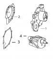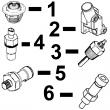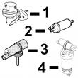
配件详情
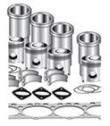
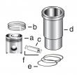
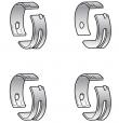
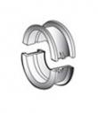
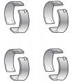
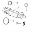
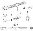
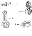
约翰迪尔 4045 4.5T/H 活塞(米) RE55512/RE505102
|
|
||||||||||||||||||||||||||||
(1)使用机器拆分连杆使用TR114083,并使用<带断裂分离式连杆的断路器。
(2)使用Oil Pan code 1901,1902&amp; 1903年,钢制油锅。
(3)使用Oil Pan code 1904&amp; 1905年,为铝油盘。
(4)用法兰头帽螺钉更换所有R78558带帽螺钉TR85363。
(5)(m)R135439,R132324,R134213。
(6)线路连接都是线程化的。
(7)1件组合式密封和护套;替换TRE59810,RE538097。
(8)在曲轴加工过程中必须保持正确的轴承轴颈半径,以确保正确的操作。
(9)检查应用程序是否正确使用。
(10)与Stanadyne DE10注射泵一起使用。
(11)锥形鼻子。
(12)直鼻。
(13)线路连接是一个&nbsp;软管倒钩&amp;一个线程。
(14)线路连接是两个软管倒钩。
(15)机器分体式和断裂式分体式连杆均可用于同一台发动机,但每个连杆必须使用正确的连杆螺栓。
6068TFM75, 6068TFM76、6068HF275、6125HF070\6125AF001,4039DFM、6125HF070、6135HF475-2、6135HF475-3 RE68345、 RE53307、RE62240、RE533095、RE502513、RE38009、R30402、RE517180、RE530107、RE62240、P524837、RE60021、RE507236、RE59588、RE549153、RE530870、SE501610、SE501609、RE70960、RE533501、RE533608、AR50041、RE515409/
供应美国约翰.迪尔(强鹿)JOHNDEERE纯正配件。P550758、P550020、P550595、P558329、P550351、P551421、P551423、P556745、P551428、P551422、P551435、P551434、P550192、P550397、P551352、P181054、P77868、P777869、P550667、P550779system repair&adjustment 02 070 6 rg41165,000006d –19–30jan01–2/10 rg11666 –un–31jan01 a—fan drive height al—alternator i—idler fd—fan drive t—tensioner cp—crank pulley adjustable fan drives (a) fan belt option fan drive option fan height 2404 23bl, 23bm 354 mm (13.9 in.) 2405, 2416 23al, 23an 317 mm (12.5 in.) 2415 23bu 354 mm (13.9 in.) 2415 23cu 391 mm (15.4in.) 2417 23cl, 23cm 391 mm (15.4 in.) rg41165,000006d –19–30jan01–3/10 rg11667 –un–31jan01 b—fan drive height al—alternator fd—fan drive t—tensioner cp—crank pulley adjustable fan drives (b) fan belt option fan drive option fan height 2403 23du 425 mm (1637 in.) 2404, 2406 23dl, 23dm 425 mm (16.7 in.) 2405 23el, 23em 462 mm (18.2 in.) 2417 23eu 462 mm (18.2 in.) 2419 23fu 499 mm (19.6 in.) 2441 23fl, 23fm 499 mm (19.6 in.) continued on next page ctm86 (20mar01) 02-070-6 powertech? 8.1 l diesel engines — base engine 032001 pn=298 cooling system repair&adjustment 02 070 7 rg41165,000006d –19–30jan01–4/10 rg11668 –un–31jan01 c—fan drive height al—alternator fd—fan drive t—tensioner cp—crank pulley adjustable fan drives (c) fan belt option fan drive option fan height 2410 23fc 499 mm (19.6 in.) 2418 23cc 391 mm (15.4in.) 2440 23dc 425 mm (16.7 in.) 2442 23ec 499 mm (19.6 in.) rg41165,000006d –19–30jan01–5/10 rg11669 –un–31jan01 d—fan drive height al—alternator fd—fan drive t—tensioner cp—crank pulley fixed fan drives (d) fan belt option fan drive option fan height 2401, 2402, 2438, 236a, 236b, 236c, 425 mm (16.7 in.) 2439 237a, 237b, 237c, 238a, 238b continued on next page ctm86 (20mar01) 02-070-7 powertech? 8.1 l diesel engines — base engine 032001 pn=299 cooling system repair&adjustment 02 070 8 rg41165,000006d –19–30jan01–6/10 rg11670 –un–31jan01 e—fan drive height al—alternator i—idler fd—fan drive t—tensioner cp—crank pulley adjustable fan drives (e) fan belt option fan drive option fan height 2411, 2437 23dl, 23dm 425 mm (16.7 in.) 2411 23eu 462 mm (18.2 in.) 2414 23fl, 23fm 499 mm (19.6 in.) 2421 23du 425 mm (16.7 in.) 2428 23fu 499 mm (19.6 in.) 2443 23el, 23em 462 mm (18.2 in.) rg41165,000006d –19–30jan01–7/10 rg11671 –un–31jan01 f—fan drive height al—alternator i—idler fd—fan drive t—tensioner cp—crank pulley fixed fan drives (f) fan belt option fan drive option fan height 2412, 2413, 2435, 236a, 236b, 236c, 425 mm (16.7 in.) 2444 237a, 237b, 237c, 238a, 238b continued on next page ctm86 (20mar01) 02-070-8 powertech? 8.1 l diesel engines — base engine 032001 pn=300 cooling system repair&adjustment 02 070 9 rg41165,000006d –19–30jan01–8/10 rg11672 –un–31jan01 g—fan drive height al—alternator i—idler fd—fan drive t—tensioner cp—crank pulley fc—freon compres*** adjustable fan drives (g) fan belt option fan drive option fan height 2407 23bu 354 mm (13.9 in.) 2407 23cu 391 mm (15.4 in.) 2408 23al, 23an 317 mm (12.5 in.) 2408 23bl, 23bm 354 mm (13.9 in.) 2408 23cl, 23cm 391 mm (15.4 in.) rg41165,000006d –19–30jan01–9/10 rg11673 –un–31jan01 h—fan drive height al—alternator fd—fan drive t—tensioner cp—crank pulley fc—freon compres*** adjustable fan drives (h) fan belt option fan drive option fan height 2409 23cc 391 mm (15.4 in.) 2420 23dc 425 mm (16.7 in.) 2422 23ec 462 mm (18.2 in.) 2423 23fc 499 mm (19.6 in.) continued on next page ctm86 (20mar01) 02-070-9 powertech? 8.1 l diesel engines — base engine 032001 pn=301 cooling system repair&adjustment 02 070 10 rg41165,000006d –19–30jan01–10/10 rg11674 –un–31jan01 j—fan drive height al—alternator i—idler fd—fan drive t—tensioner cp—crank pulley fc—freon compres*** adjustable fan drives (j) fan belt option fan drive option fan height 2429, 2430, 2434 23al, 23am, 23an 317 mm (12.5 in.) 2431, 2432 23bl, 23bm 354 mm (13.9 in.) 2445, 2446 23cl, 23cm 391 mm (15.4 in.) 2429, 2430 23bu 354 mm (13.9 in.) 2431, 2432 23cu 391 mm (15.4 in.) 2426, 2427, 2433, 23dl, 23dm 425 mm (146.7 in.) 2436 2424, 2425 23du 425 mm (16.7 in.) 2447, 2448 23cf 391 mm (15.4 in.) rg,rg34710,1241 –19–23oct97–1/3 checking belt tensioner spring tension and belt wear rg7380 –un–28nov97 belt tensioner a—cast stop b—cast stop belt drive systems equipped with automatic (spring) belt tensioners cannot be adjusted/repaired. the automatic belt tensioner is designed to maintain proper belt tension over the life of the belt. if tensioner spring tension is not within specification, replace tensioner assembly. checking belt wear the belt tensioner is designed to operate within the limit of arm movement provided by the cast s*** (a&b) when correct belt length&geometry are used. visually inspect cast s*** (a&b) on belt tensioner assembly. if the tensioner stop on swing arm (a) is hitting the fixed stop (b), check mounting brackets (alternator, belt tensioner, idler pulley, etc.)&the belt length. replace belt as needed (see operator’s manual). ctm86 (20mar01) 02-070-10 powertech? 8.1 l diesel engines — base engine 032001 pn=302 continued on next page cooling system repair&adjustment 02 070 11 rg,rg34710,1241 –19–23oct97–2/3 rg7382 –un–28nov97 checking belt tensioner a—mark on swing b—mark on tensioner mounting base checking tensioner spring tension: a belt tension gauge will not give an accurate measure of the belt tension when automatic spring tensioner is used. measure tensioner spring tension using a torque wrench and procedure outlined below: 1. release tension on belt using a long-handle 1/2-in. breaker bar in tension arm. remove belt from pulleys. 2. release tension on tension arm&remove breaker bar. 3. put a mark (a) on swing arm of tensioner as shown. 4. measure 21 mm (0.83 in.) from (a)&put a mark (b) on tensioner mounting base. rg,rg34710,1241 –19–23oct97–3/3 rg7381 –un–28nov97 measuring belt tensioner a—mark b—mark 5. rotate the swing arm using a torque wrench until marks (a&b) are aligned. 6. record torque wrench measurement&compare with specification below. replace tensioner assembly as required. specification belt tensioner spring—tension . 24-28 n?m (17-21 lb-ft) ctm86 (20mar01) 02-070-11 powertech? 8.1 l diesel engines — base engine 032001 pn=303 cooling system repair&adjustment 02 070 12 rg,rg34710,1242 –19–23oct97–1/1 inspect&install fan assembly rg4797 –un–14dec88 fan assembly several fan drive ratios are available, allowing a closer matching of fan speed to application. 1. inspect fan blades for bent/damaged condition. bent blades reduce cooling system efficiency&throw the fan out of balance. replace fan if blades are bent or damaged. note: engines may be equipped with either suction-type fan/a blower-type fan, depending on application. 2. install fan on pulley/pulley spacer hub. tighten cap screws (with lock washers) to specifications. specification fan-to-fan hub/pulley—torque . 47 n?m (35 lb-ft) ctm86 (20mar01) 02-070-12 powertech? 8.1 l diesel engines — base engine 032001 pn=304 cooling system repair&adjustment 02 070 13 rg,rg34710,1243 –19–23oct97–1/1 visually inspect coolant pump rg7061 –un–26nov97 coolant pump weep hole a—weep hole inspect weep hole: inspect coolant pump weep hole (a) in timing gear cover for oil/coolant leakage. oil leakage indicates a damaged rear seal. coolant leakage indicates a damaged front seal. replace complete coolant pump assembly if leakage is detected; individual repair parts are not available. inspect for impeller contact with cover: 1. remove radiator-to-coolant pump hose from coolant pump inlet elbow. 2. using a flashlight, inspect i.d. of coolant pump cover for internal impeller contact. impeller contact with cover usually indicates that impeller has moved on shaft/there is a damaged bearing. replace coolant pump assembly&cover as necessary if impeller contact is detected. ctm86 (20mar01) 02-070-13 powertech? 8.1 l diesel engines — base engine 032001 pn=305 cooling system repair&adjustment 02 070 14 rg,rg34710,1244 –19–23oct97–1/3 remove coolant pump assembly rg7044 –un–26nov97 coolant pump drain valve rg7143 –un–26nov97 cylinder block drain valve a—coolant pump drain valve b—drain valve the coolant pump should be removed from the timing gear cover for replacement purpose only. there are no service parts available to repair coolant pump, replace as a complete assembly. caution: explosive release of fluids from pressurized cooling system can cause serious burns. wait until engine coolant is cool enough to touch with bare hands before draining. slowly loosen radiator cap to first stop to relieve pressure. 1. open coolant pump drain valve (a)&block drain valve (b) to drain coolant from engine. rg,rg34710,1244 –19–23oct97–2/3 rg7063 –un–26nov97 removing coolant pump cover a—coolant pump cover b—bypass tube 2. remove hose from coolant pump cover inlet elbow, shown removed. 3. remove six cap screws securing coolant pump cover (a) to timing gear cover&remove coolant pump cover with bypass tube (b). 4. remove gasket from timing gear cover&discard. remove bypass tube from cover. inspect bypass tube seal in coolant pump cover, replace seal as needed. see replace bypass tube seal in coolant pump cover later in this group. ctm86 (20mar01) 02-070-14 powertech? 8.1 l diesel engines — base engine 032001 pn=306 continued on next page cooling system repair&adjustment 02 070 15 rg,rg34710,1244 –19–23oct97–3/3 rg7062 –un–07sep94 removing coolant pump 5. compress retaining ring ends with a small needle-nose pliers as shown. 6. grasp impeller with a large pliers&pull coolant pump from timing gear cover using a slight rocking motion until assembly is removed from timing gear cover. discard coolant pump assembly. ctm86 (20mar01) 02-070-15 powertech? 8.1 l diesel engines — base engine 032001 pn=307 cooling system repair&adjustment 02 070 16 rg,rg34710,1245 –19–23oct97–1/1 install coolant pump assembly rg7227 –un–05dec97 assembling coolant pump rg7062 –un–07sep94 installing coolant pump a—o-rings b—retaining ring 1. thoroughly clean&inspect coolant pump mounting bore in timing gear cover before installing pump assembly. 2. install two new o-rings (a) in rear grooves of coolant pump housing&apply a light coat of clean engine oil to o-rings. 3. install a new retaining ring (b) in front (smallest) groove of coolant pump housing&compress both ends of retaining ring together with a small needle-nose pliers. 4. install a new foam filter into coolant pump weep hole. note: retaining ring ends should be at 3 o’clock position and coolant pump weep hole should align with hole in timing gear cover when installing coolant pump assembly. 5. compress retaining ring ends&install coolant pump assembly into pilot bore of timing gear cover. make sure that pump drive gear properly meshes with crankshaft gear. 6. release retaining ring ends&verify that retaining ring is firmly seated in groove of timing gear cover. 7. install coolant pump cover with bypass tube using a new gasket. tighten cap screws to specifications. coolant pump cover mounting cap screws—specification 5/16-in. mounting cap screws— torque . 27 n?m (20 lb-ft) 3/8-in. cap screws—torque . 47 n?m (35 lb-ft) important: if a new aluminum coolant pump cover has been installed, the cooling system must be completely drained and flushed. refer to operators manual for flushing procedure&the recommended coolant solution. ctm86 (20mar01) 02-070-16 powertech? 8.1 l diesel engines — base engine 032001 pn=308 cooling system repair&adjustment 02 070 17 rg,rg34710,1246 –19–23oct97–1/1 replace bypass tube seal in coolant pump cover rg7063 –un–26nov97 bypass tube in coolant pump cover rg7064 –un–26nov97 installing bypass tube seal a—coolant pump cover b—bypass tube c—bypass tube seal d—jdg908 seal driver 1. drain cooling system&remove coolant pump cover (a) with bypass tube (b). discard cover gasket. 2. carefully clamp cover in a soft-jawed vise&remove bypass tube seal. be careful not to damage machined gasket surface of cover. 3. install new seal (c) using jdg908 seal driver (d). drive seal into bore until driver bottoms. 4. remove cover from vise&inspect seal installation and also machined gasket surfaces. rg,rg34710,1247 –19–23oct97–1/2 remove&test thermostats rg6966 –un–26nov97 removing thermostat cover a—thermostat cover caution: explosive release of fluids from pressurized cooling system can cause serious burns. do not drain coolant until coolant temperature is below operating temperature. always loosen cooling system filler cap, radiator cap,/drain valve slowly to relieve pressure. 1. visually inspect the area around the coolant manifold for leaks. partially drain coolant from the cooling system. 2. remove thermostat cover (a) with gasket. remove and discard all gasket material. ctm86 (20mar01) 02-070-17 powertech? 8.1 l diesel engines — base engine 032001 pn=309 continued on next page cooling system repair&adjustment 02 070 18 rg,rg34710,1247 –19–23oct97–2/2 rg6967 –un–28jul94 removing thermostats 3. remove thermostats. 4. inspect thermostats for debris/damage,&test each thermostat using an approved testing procedure. see inspect thermostat&test opening temperature in group 150 for testing procedure. thermostats should start to open within the range specified below. specification thermostat 82°c (180°f)— opening temperature 80—84°c (175—182°f) if either thermostat fails to open within this range, replace both thermostats as a set. rg,rg34710,1249 –19–23oct97–1/1 remove coolant manifold rg6968 –un–26nov97 removing coolant manifold a—thermostats b—bore of coolant manifold c—bypass pipe 1. drain coolant&remove thermostat cover from coolant manifold (shown removed). remove thermostats (a). 2. remove three coolant manifold-to-cylinder head cap screw, remove coolant manifold (b)&dislodge coolant bypass tube as manifold is removed. note: pull coolant manifold straight out (toward front of engine) approximately 6.35 mm (0.25 in.) to disengage from locator (spring) pin, then lift straight up to disengage from bypass tube (c). 3. remove&discard o-ring from bore of coolant manifold. ctm86 (20mar01) 02-070-18 powertech? 8.1 l diesel engines — base engine 032001 pn=310 cooling system repair&adjustment 02 070 19 rg,rg34710,1248 –19–23oct97–1/1 install thermostats rg6967 –un–28jul94 installing thermostats note: install thermostats in groove in housing first. then install gasket after thermostat is properly seated in grooves. 1. install thermostats. install a new gasket on housing or in cover, as applicable. 2. install cover&tighten cap screws to specifications. specification cast iron thermostat cover-to-cylinder head—torque 47 n?m (35 lb-ft) aluminum thermostat cover-to-cylinder head—torque 30 n?m (22 lb-ft) important: air must be expelled from cooling system when system is refilled. loosen temperature sending unit fitting at rear of cylinder head/plug in thermostat housing to allow air to escape when filling system. retighten fitting when all the air has been expelled. ctm86 (20mar01) 02-070-19 powertech? 8.1 l diesel engines — base engine 032001 pn=311 cooling system repair&adjustment 02 070 20 rg,rg34710,1250 –19–23oct97–1/1 install coolant manifold rg6968 –un–26nov97 installing coolant manifold a—thermostats b—bore of coolant manifold c—bypass pipe 1. install a new o-ring into coolant manifold o-ring bore. lubricate o-ring with grease to ease bypass pipe installation. install bypass pipe (c) into bore of coolant manifold (b). be careful not to cut o-ring. 2. install coolant manifold assembly. be sure coolant manifold is properly positioned on spring pin (in front face of cylinder head)&that bypass pipe is fully seated in coolant manifold&coolant pump cover bores. 3. apply loctite? 242 thread sealer to coolant manifold-to-cylinder head cap screw threads 360 degrees (except for the leading one to three threads). tighten coolant manifold cap screws to specifications. specification coolant manifold-to-cylinder head cap screws—torque 35 n?m (25 lb-ft) 4. install thermostats&cover. see install thermostats, earlier in this group. loctite is a registered trademark of loctite corp. dpsg,ouo1004,807 –19–21apr99–1/1 remove&install coolant temperature switch 1. disconnect wiring&remove switch. 2. coat threads of switch with ty9375 pipe sealant with teflon?. 3. install switch&tighten to the following specifications. specification coolant temperature switch— torque . 45 n?m (33 lb-ft) teflon is a registered trademark of du pont co. ctm86 (20mar01) 02-070-20 powertech? 8.1 l diesel engines — base engine 032001 pn=312 cooling system repair&adjustment 02 070 21 rg,rg34710,1251 –19–23oct97–1/1 servicing of engine coolant heater refer to ctm67, engine acces***ies, group 25, for service of the block-type engine coolant heater. see remove coolant heater—block type in group 25 of ctm67. rg,rg34710,1252 –19–23oct97–1/1 complete final assembly note: consult your engine operator’s manual/see group 002 of this ctm for coolant recommendations in your area. see diesel engine coolant in group 002. 1. fill cooling system to proper level with the proper coolant. 2. start engine&run for several minutes to check for leaks in the cooling system. 3. after fan belts cool, check belt tension as detailed in your operator’s manual. ctm86 (20mar01) 02-070-21 powertech? 8.1 l diesel engines — base engine 032001 pn=313 cooling system repair&adjustment 02 070 22 ctm86 (20mar01) 02-070-22 powertech? 8.1 l diesel engines — base engine 032001 pn=314 group 080 air intake&exhaust system repair&adjustment 02 080 1 rg,rg34710,1256 –19–28apr99–1/2 extending turbocharger life turbochargers are designed to last the life of the engine, but, because they operate at such high speeds (100,000 rpm/more); a moment’s carelessness can cause them to fail in seconds. the major causes of turbocharger failures are: ? lack of lube oil (quick starts&hot shutdowns) ? oil contamination ? ingestion of foreign objects ? restricted oil drainage ? low oil level ? operation on excessive side slopes ? abnormally high exhaust temperatures lack of lube oil oil not only lubricates the turbocharger’s spinning shaft and bearings, it also carries away heat. when oil flow s***/is reduced, heat is immediately transferred from the hot turbine wheel to the bearings, which are also heating up because of the increased friction due to the lack of oil. this combination causes the turbocharger shaft temperature to increase rapidly. if oil flow does not increase&the process continues, bearings will fail. once the bearings fail (which can happen in just seconds) seals, shaft, turbine and compres*** wheels can also be damaged. the principle causes of turbocharger bearing lubrication problems are low oil pressure, a bent, plugged/undersized oil lube supply line, plugged or restricted oil galleries in the turbocharger,/improper machine start-up&shutdown procedure. oil levels&pressure should always be closely monitored&all worn hoses&lines should be replaced. the turbocharger oil supply line should be checked frequently to make sure it is not kinked or bent&it should always be replaced with a line of equal size, length&strength. the easiest way to damage a turbocharger is through improper start-up&shutdown procedures. always idle the engine for at least 30 seconds (no load) after start-up&before shutdown. warming the engine up before applying a load allows oil pressure to build up and lines to fill with oil. idling the engine before shutdown allows the engine and turbocharger to cool. “hot” shutdowns can cause the turbocharger to fail because after high-speed operation the turbocharger will continue to rotate long after the engine has been shut off&oil pressure has dropped to zero. this will cause heat to build up and possibly damage bearings. it can also cause carbon and varnish deposits to form. oil contamination a second cause of turbocharger failures is contaminated oil. it can be caused by a worn or damaged oil filter/not changing the lube oil at recommended intervals. expecting the oil filter to remove dirt, sand, metal chips, etc. from the oil before they reach the engine/turbocharger can be a costly mistake because contaminated oil may completely bypass the engine oil filter if the oil filter/oil cooler is clogged, if the filter element is improperly installed, or if the oil is thick during cold weather. four good ways of avoiding oil contamination are: ? always inspect the engine thoroughly during major overhaul. 宜春约翰迪尔强鹿3029柴油机电热塞供应商,重庆美国JohnDeere发电机皮带R135193供应商,郑州johndeere约翰迪尔强鹿柴油机热交换器市场报价,日喀则强鹿柴油滤芯P550135代理商,百色JohnDeere主轴瓦RE529319多少钱,扬州约翰迪尔柴油发电机配件RE507852批发,西安强鹿柴油机进油管代理商,吐鲁番JohnDeere温器座RE64354供货商,湖北强鹿RE522372柴油滤芯价格行情,宿州强鹿johndeere约翰迪尔涡轮增压器供应商,巴音郭楞强鹿6090柴油发动机皮带张紧轮的价格,连云港强鹿柴油机AT21134止推轴承代理,周口约翰迪尔发动机汽缸盖缸体哪家好,玉树强鹿柴油发动机节恒温器市场报价,通化约翰迪尔C120联合收割机发动机配件批发,莱芜约翰迪尔水泵总成RE500734厂家供货,长沙强鹿R115250皮带轮批发商,天水强鹿柴油发电机组仪表盘厂家批发,湖州约翰迪尔主轴瓦RE65165价格,晋中johndeere主轴瓦公司,武汉强鹿T20073凸轮随动件代理,广州约翰.迪尔空气滤清器RE16809一级代理,甘孜右平衡轴TRE500448约翰迪尔柴油机市场报价,澳门离岛强鹿柴油机水泵哪家买,株洲强鹿加大止推轴承瓦RE534183厂家供货,淮北强鹿发电机配件6068TF258找哪家,邵阳强鹿6081柴油机机油泵哪家好,济南约翰迪尔E240LC挖掘机发动机配件哪家买,乌海JohnDeere传感器RE522794厂家供货,甘南JohnDeere挺铜柱RE540586信息,巴彦淖尔强鹿约翰迪尔3029气缸盖螺丝批发,咸阳约翰迪尔发动机气门挺杆厂家供应,齐齐哈尔JohnDeere水温传感器el52222公司,湖北约翰迪尔3029柴油机排气门厂家批发,淄博约翰迪尔R58979哪家好,南阳强鹿机滤RE57394公司,惠州约翰迪尔装载机发动机曲轴批发商,博尔塔拉美国强鹿JOHNDEERE柴油发电机配件厂家供应,上海约翰迪尔6068柴油机排气门批发价,信阳约翰迪尔6068柴油机气门油封的价格,兴安约翰迪尔强鹿喷油器垫圈价格行情,新疆约翰迪尔活塞RE529264一级代理,淄博约翰迪尔R58979厂家供应,鄂州强鹿柴油机喷油器代理商,安康强鹿4045柴油机曲轴哪家好,新疆约翰迪尔6081柴油机活塞环的价格,新界强鹿柴油发动机启动机供货商,阜新美国JohnDeere起动机RE70960哪里买,广安强鹿柴油机4045主轴瓦公司,潮州强鹿柴油机原装机油滤清器RE504836批发商,聊城约翰迪尔缸套水封圈AR98850找哪家,资阳强鹿柴油机气门挺杆的价格,丽江强鹿柴油发动机3029修理包哪家买,东莞约翰迪尔6J-1654拖拉机发动机配件供应商,怒江强鹿6090柴油发动机曲轴信息,宿州johndeere约翰迪尔强鹿柴油机油底壳信息,克孜勒苏强鹿6090柴油机主轴瓦信息,巴音郭楞约翰迪尔强鹿3029柴油机气门弹簧座找哪家,南充强鹿6081柴油机气门座圈代理商,乐山约翰迪尔发动机机油泵多少钱,七台河约翰迪尔强鹿气门室盖垫片R524468价格,博尔塔拉美国强鹿JOHNDEERE柴油发电机配件代理商,六盘水约翰迪尔6081柴油机温度传感器一级代理,恩施johndeere约翰迪尔强鹿柴油机喷油器批发价,台湾强鹿6068柴油机喷油器公司,look especially for any sludge/debris left in lube oil galleries. ? change lube oil at recommended intervals. analysis of oil samples at filter change periods can help identify potentially harmful contaminants in the oil. ? clean the area around the oil fill cap before adding oil. ? use a clean container when adding oil. ctm86 (20mar01) 02-080-1 powertech? 8.1 l diesel engines — base engine 032001 pn=315 continued on next page air intake&exhaust system repair&adjustment 02 080 2 rg,rg34710,1256 –19–28apr99–2/2 ingestion of foreign objects the third cause of turbocharger damage is the ingestion of foreign objects. these particles can be ingested&cause damage to the turbocharger on both compres***&turbine sides. this is easy to avoid. on the compres*** side, foreign objects usually take the form of dust, sand,/shreds of air cleaner element that enter through improperly installed air cleaner elements. leaky air inlet piping (loose clamps or torn rubber joints)/torn pleats in dry-type air cleaner elements also create problems. the result is erosion of compres*** blades that can cause the delicately balanced wheel to wobble. important: whenever an internal engine failure (valve, valve seat, piston) occurs, a thorough inspection of the turbocharger must be performed before returning engine to service. restricted oil drainage a fourth cause of turbocharger damage is restricted lube oil drainage. the lubricating oil carries away heat generated by friction of the bearings&from the hot exhaust gases. if drainage back to the sump is impeded, the bearings will overheat with damage that will ultimately lead to failure. there are two primary reasons for restricted drainage. a blocked drain tube, due to either damage/a buildup of sludged oil,/high crankcase pressure, which can be due to restricted crankcase breather or excessive engine blow-by. periodically check both the turbocharger oil drain tube and engine breather tube for damage/restriction. correction of these conditions leads to longer turbocharger life. abnormally high exhaust temperatures a fifth cause of turbocharger damage is abnormally high exhaust temperatures. elevated exhaust temperatures cause coking of oil which can lead to bearing failure. extreme over-temperature operation can cause wheel burst. there are two basic causes of over-temperature. the first is restricted air flow&the second is overpowering the engine. in either case the engine has more fuel than available air for proper combustion; this overfueled condition leads to elevated exhaust temperatures. causes of restricted air flow can include damaged inlet piping, clogged air filters, excessive exhaust restriction, or operation at extreme altitudes. overpowering generally is due to improper fuel delivery/injection timing. if overtemperature operation has been identified, an inspection of the air inlet&exhaust systems should be performed. also, check the fuel delivery&timing. ctm86 (20mar01) 02-080-2 powertech? 8.1 l diesel engines — base engine 032001 pn=316 air intake&exhaust system repair&adjustment 02 080 3 rg,rg34710,1257 –19–23oct97–1/1 remove turbocharger rg7004 –un–26nov97 removing turbocharger a—oil inlet line b—oil return tube caution: after operating engine, allow exhaust system to cool before removing turbocharger. important: when cleaning turbocharger, do not spray directly into compres*** cover or turbine housing. if turbocharger inspection is required, do not clean exterior prior to removal. doing so may wash away evidence of a potential failure mode. see turbocharger inspection later in this group. thoroughly clean exterior of turbocharger&surrounding area to prevent entry of dirt into the air intake system during removal. 1. disconnect air intake&exhaust piping from turbocharger (shown disconnected). 2. disconnect turbocharger oil inlet line (a) from elbow adapter. 3. disconnect turbocharger oil return (drain) tube (b). remove&discard gasket. 4. if equipped, disconnect wastegate diaphragm hose. 5. remove four turbocharger mounting cap screws with washers securing turbocharger to rear exhaust manifold&remove turbocharger. 6. cap/plug all openings on engine (exhaust and intake manifold related)&place turbocharger on a clean flat table for inspection. 7. perform turbocharger seven-step inspection, as described later, if failure mode has not been determined. see turbocharger inspection later in this group. ctm86 (20mar01) 02-080-3 powertech? 8.1 l diesel engines — base engine 032001 pn=317 air intake&exhaust system repair&adjustment 02 080 4 rg,rg34710,1258 –19–23oct97–1/2 turbocharger failure analysis the following is a guide for diagnosing the cause of turbocharger failures after removal from the engine. problem possible cause suggested remedy compres*** housing inlet defects foreign object damage objects left in intake system. disassemble&inspect intake system for foreign objects (this group). inspect engine for internal damage. leaking and/or defective intake system. inspect air intake system connections including air filter; repair as required (this group). inspect air intake related engine components. compres*** wheel rub bearing failure. determine if engine and/or operator contributed to lack of lubrication, contaminated lubrication, excessive temperature,/debris generating engine failure in progress. correct as required. manufacturing defects. correct as required. compres*** housing outlet defects oil and/or dirt in housing restricted air intake system. inspect&clean air cleaner. prolonged periods of low rpm engine check with operator to confirm conditions. (see idling. operator’s manual.) defective oil seal ring.石家庄约翰迪尔AT21139止推轴承代理,兰州强鹿气门油封RE519115批发价,芜湖强鹿约翰迪尔3029摇臂供货商,贵港约翰迪尔联合收割机发动机缸盖价格行情,和田强鹿柴油发动机缸套水封圈AR98850多少钱,锦州约翰迪尔6068HF475配件价格,鹤壁强鹿4045大修件RE527299哪家好,廊坊强鹿柴油发动机加大止推轴承瓦RE504199厂家价格,北海约翰迪尔4045柴油发动机水泵总成多少钱,上饶强鹿柴油机四配套DZ10211代理商,玉林约翰迪尔强鹿曲轴前代理,吉林约翰迪尔发动机四配套厂家供货,衢州强鹿柴油机大修配件信息, repair as required (this group). restricted oil drain line. inspect&clear oil drain line as required. turbine housing inlet defects oil in housing internal engine failure. inspect&repair engine as required. oil leaking from compres*** housing verify that oil is in compres*** housing&refer to seal. “compres*** housing outlet defects” as listed earlier in this chart. center wall deteriorated excessive operating temperature. check for restricted air intake. check engine for overfueling. check injection pump timing. continued on next page ctm86 (20mar01) 02-080-4 powertech? 8.1 l diesel engines — base engine 032001 pn=318 air intake&exhaust system repair&adjustment 02 080 5 rg,rg34710,1258 –19–23oct97–2/2 turbine housing outlet defects turbine wheel rub bearing failure. determine if engine and/or operator contributed to lack of lubrication, contaminated lubrication, excessive temperature,/debris generating engine failure in progress. correct as required. manufacturing defect. correct as required (this group). foreign object damage internal engine failure. inspect&repair engine as required. objects left in intake system. disassemble&inspect air intake system (this group). leaking air intake system. correct as required (this group). oil and/or excessive carbon internal engine failure. verified by oil in turbine housing. correct as required. turbine seal failure. inspect for excessive heat from overfueling and/or restricted air intake. prolonged periods of low rpm engine ask operator to run engine under load/at a higher idling. rpm (see operator’s manual). restricted oil drain line. inspect&clear oil drain line as required. external center housing&joint defects leaks from casting defective casting. replace turbocharger (this group). defective gasket. verify if leaks are occurring at gasket joints. leaks from joints loose attaching screws. tighten to specifications in ctm (this group). defective gasket. inspect&repair as required. internal center housing defects excessive carbon build-up in housing hot engine shutdown. review proper operation with operator as shown in or on shaft operator’s manual. excessive operating temperature. restricted air intake; overfueling/mistimed engine. restricted oil drain line. inspect&clean oil drain lines as required. operating engine at high speeds&idle engine for a few minutes to allow oil to reach loads immediately after start-up. bearings before applying heavy loads. ctm86 (20mar01) 02-080-5 powertech? 8.1 l diesel engines — base engine 032001 pn=319 air intake&exhaust system repair&adjustment 02 080 6 rg,rg34710,1259 –19–23oct97–1/12 turbocharger inspection the following inspection procedure is recommended for systematic failure analysis of a suspected failed turbocharger. this procedure will help to identify when a turbocharger has failed,&why it has failed so the primary cause of the failure can be corrected. proper diagnosis of a non-failed turbocharger is important for two reasons. first, identification of a non-failed turbocharger will lead to further investigation and repair of the cause of a performance complaint. second, proper diagnosis eliminates the unnecessary expense incurred when a non-failed turbocharger is replaced. the recommended inspection steps, which are explained in detail on following pages, are: ? compres*** housing inlet&compres*** wheel. ? compres*** housing outlet. ? turbine housing inlet. ? turbine housing outlet&turbine wheel. ? external center housing&joints. ? perform axial end play test note: to enhance the turbocharger inspection, an inspection sheet (form no. df-2280 available from distribution service center—english only) can be used that lists the inspection steps in the proper order&shows potential failure modes for each step. check off each step as you complete the inspection&record any details/problems obtained during inspection. retain this with the work order for future reference. rg,rg34710,1259 –19–23oct97–2/12 rg4523 –un–03nov97 checking inlet&compres*** wheel a—compres*** wheel compres*** housing inlet&compres*** wheel 1. check compres*** inlet&compres*** wheel (a) for foreign object damage. note: foreign object damage may be extensive or minor. in either case, the source of the foreign object must be found&corrected to eliminate further damage. 2. mark findings on your KEY PART NO. PART NAME QTY SERIAL NO. F F F REMARKS
1 R60914 SET SCREW 1 X
2 R53918 PACKING 1 X
3 T31556 NUT 1 X
4 R68715 PIN 1 X
5 AR89339 SEAL 1 X
6 AR89578 LEVER 1 X
7 24M7054 WASHER 1 X 6.400 X 12 X 1.600 MM
8 T24229 LOCK WASHER 2 X
9 R68716 NUT 1 X
10 R129240 LEVER 1 X (A) (SUB R504886)
11 19M8826 SCREW 2 X M6 X 16
12 R53976 SCREW 1 X (B)
13 24H1287 WASHER 1 X (B) 9/32" X 5/8" X 0.065"
14 RE54741 LEVER 1 X (C)
15 R68438 RETAINER 1 X
16 R53955 O-RING 1 X
(A) THROTTLE (TWO HOLES AT TOP) (B) NOT INCLUDED (C) SHUT-OFF
MANETTE DES GAZ NON INCLUS ROBINET D’ARRET
DROSSELKLAPPE NICHT MIT ABSCHALTUNG
ACCELERATORE NON COMPRESO RUBINETTO D’ARRESTO
ACELERADOR NO FORMA PARTE GRIFO DECIERRE
GASREGLAGE INGAAR INTE AVSTAENGING
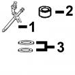
KEY PART NO. PART NAME QTY SERIAL NO. F F F REMARKS
1 R126207 BRACKET 1 X
2 14M7165 LOCK NUT 2 X M6
3 RE53507 SOLENOID 1 X (A) (12 V)
4 19H1914 CAP SCREW 1 X 1/4" X 1"
5 24H1287 WASHER 1 X 9/32" X 5/8" X 0.065"
6 RE54741 LEVER 1 X
7 03M7068 BOLT 1 X M6 X 20
8 19H1900 CAP SCREW 2 X 5/16" X 3/4"
9 24H1136 WASHER 2 X 11/32" X 11/16" X 0.065"
10 R104592 PIPE PLUG 1 X
11 R128694 BASE 1 X (SUB FOR R127415) (ALSO ORDER (2)
R104592)
(A) ENERGIZE TO RUN
METTRE SOUS TENSION POUR FAIRE MARCHER
FUER BETRIEB AKTIVIEREN
ATTIVARE PER IL FUNZIONAMENTO
ACTIVAR PARA MARCHA
MAGNETISERA FOER ATT SAETTA IGAANG
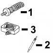
KEY PART NO. PART NAME QTY SERIAL NO. F F F REMARKS
1 .. HOLDER NA X
2 T24210 O-RING 6 X
3 R76358 O-RING 1 X
4 14M7272 NUT 3 X M6
5 12M7006 LOCK WASHER 3 X 0.236"
6 R67879 GASKET 1 X
7 R53899 WASHER 1 X
8 AR77114 CONTROL VALVE 1 X
9 R53901 WASHER 1 X
10 R63016 ADAPTER 1 X
11 RE502650 FITTING 1 X
