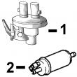
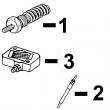
配件详情
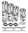
发动机大修包
型号 数量 描述
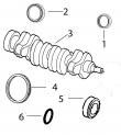
TAR67942 1 后油封
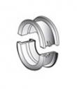
TAT21139 1 止推瓦(标准)
TMX504 1 试剂盒 (4)
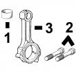
TR504300 3 连杆衬套 PT 32 mm
TR80033 6 连杆螺钉
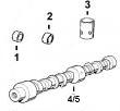
TRE27348 3 连杆瓦(标准
TRE27352 3 主轴瓦(标准)
TRE31617 6 气门密封 STEM LITER ENG
TRE44574 1 前油封
TRE501578 1 大修包
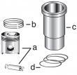
TRE66968 3 活塞缸套四配套,包括活塞,活塞环,活塞销,缸套,卡簧,阻水圈
型号 数量 描述
TAR67942 1 后油封
TAT21139 1 止推瓦(标准)
TMX504 1 试剂盒 (4)
TR501124 6 连杆螺钉
TR504300 3 连杆衬套 PT 32 mm
TRE27348 3 连杆瓦(标准
TRE27352 3 主轴瓦(标准)
TRE31617 6 气门密封 STEM LITER ENG
TRE44574 1 前油封
TRE501578 1 大修包
TRE66968 3 活塞缸套四配套,包括活塞,活塞环,活塞销,缸套,卡簧,阻水圈(RE61467)
发动机内部修理套件
型号 数量 描述
TAT21139 1 止推瓦(标准)
TR80033 6 连杆螺钉
TR97341 1 GASKET, OIL PAN 3 CYL
TRE27348 3 连杆瓦(标准
TRE27352 3 主轴瓦(标准)
TRE31617 6 气门密封 STEM LITER ENG
TRE38850 1 GASKET, CYL HEAD SET
TRE66968 3 活塞缸套四配套,包括活塞,活塞环,活塞销,缸套,卡簧,阻水圈(RE61467)
型号 数量 描述
TAT21139 1 止推瓦(标准)
TR501124 6 连杆螺钉
TR97341 1 GASKET, OIL PAN 3 CYL
TRE27348 3 连杆瓦(标准
TRE27352 3 主轴瓦(标准)
TRE31617 6 气门密封 STEM LITER ENG
TRE38850 1 GASKET, CYL HEAD SET
TRE66968 3 活塞缸套四配套,包括活塞,活塞环,活塞销,缸套,卡簧,阻水圈(RE61467)
约翰迪尔 3029 2.9D/T 活塞(米) RE520573
|
|
|
发动机和设备型号
|
孔径:
4.19 in 106.5 mm
销径 Ø:
1.3 in 32 mm
|
|
|
4045TF120、6068HF120、6068HF475、6068TF220、6068TF001、6068HF158、6135HF485、PE6068HF275BA5E、4045HFU82、4045HFU79、4045HF、6068HF183、6068HFU72、6090HFU75、6068HFUFU79、6068HFU82、6068HF183remove&install oil pressure sen*** rg10296 –un–27aug99 oil pressure sen*** the ecu monitors engine oil pressure for engine protection purposes. under low oil pressure conditions, the ecu will derate engine power&in some applications, may shut the engine down. a diagnostic trouble code/warning light is generated. 1. disconnect oil pressure sen*** wiring connector and remove sen*** from oil cooler housing. 2. coat sen*** o-ring with jdt405 high temperature grease. coat threads of sen*** with loctite? 592 pipe sealant with teflon?. install sen*** in oil cooler housing&tighten to specifications. specification engine oil pressure sen***— torque .. 9 n?m (80 lb-in.) engine oil pressure sen*** adapter-to-filter housing— torque 11 n?m (97 lb-in.) 3. install sen*** wiring connector. loctite is a registered trademark of loctite corp. teflon is a registered trademark of du pont co. ctm188 (20mar01) 02-110-6 powertech 10.5 l & 12.5 l level 6 fuel system 032001 pn=84 electrical engine control repair&adjustment 02 110 7 rg,rg34710,271 –19–13aug99–1/1 remove&install manifold air temperature (mat) sen*** rg8548 –un–20may98 manifold air temperature (mat) sen*** the ecu uses the manifold air temperature&manifold absolute pressure sen*** signals for engine airflow calculations. 1. disconnect manifold air temperature sen*** wiring connector. 2. remove sen*** from bottom side of intake manifold (6105h&6125h engines)/aftercooler (6105a engines). 3. coat o-ring with jdt405 high temperature grease. 4. install mat sen*** in bottom side of intake manifold or aftercooler. tighten to specifications. specification manifold air temperature (mat) sen***—torque . 10 n?m (7.5 lb-ft) 5. install sen*** wiring connector. ctm188 (20mar01) 02-110-7 powertech 10.5 l & 12.5 l level 6 fuel system 032001 pn=85 electrical engine control repair&adjustment 02 110 8 rg,rg34710,272 –19–13aug99–1/1 remove&install manifold absolute pressure (map) sen*** rg8547 –un–20may98 manifold absolute pressure (map) sen*** the ecu uses the manifold absolute pressure and manifold air temperature sen*** signals for engine airflow calculations. 1. disconnect manifold absolute pressure sen*** hose (6105a&6125a engines) and/or wiring connector. 2. remove sen*** from intake manifold/aftercooler. 3. remove two cap screws&remove sen***. 4. coat o-ring with jdt405 high temperature grease. 5. install sen*** on intake manifold/aftercooler. tighten two cap screws to specifications. specification manifold absolute pressure (map) sen***—torque. 7 n?m (5 lb-ft) 6. connect hose (6105a&6125a engines)&/or wiring connector. ctm188 (20mar01) 02-110-8 powertech 10.5 l & 12.5 l level 6 fuel system 032001 pn=86 electrical engine control repair&adjustment 02 110 9 rg,rg34710,273 –19–13aug99–1/1 remove&install camshaft position sen*** rg8546 –un–20may98 camshaft position sen*** important: camshaft position sen*** must be removed for camshaft removal and installation. the ecu monitors the position of the camshaft and crankshaft to determine piston position&the optimum time to start&stop injecting fuel. the camshaft position sen*** monitors camshaft position&sends it to the ecu. 1. disconnect camshaft position sen*** wiring connector. 2. remove sen*** from cylinder head. 3. coat o-ring with jdt405 high temperature grease. 4. install sen*** in cylinder head. tighten to specifications. specification camshaft position sen***— torque . 14 n?m (10 lb-ft) ctm188 (20mar01) 02-110-9 powertech 10.5 l & 12.5 l level 6 fuel system 032001 pn=87 electrical engine control repair&adjustment 02 110 10 rg,rg34710,274 –19–13aug99–1/2 remove&install crankshaft position sen*** rg10290 –un–24aug99 crankshaft position sen*** rg10380 –un–19oct99 using jdg1334 depth checking tool a—machined mounting surface (spotface) b—crankshaft position sen*** c—pin (in jdg1334 depth checking tool) d—sen*** depth low (shim required) e—sen*** depth correct (no shim required) f—sen*** depth too high (requires investigation) g—jdg1334 depth checking tool h—crankshaft timing wheel note: crankshaft vibration damper&front seal shown removed. the ecu monitors the position of the crankshaft and camshaft to determine piston position&the optimum time to start&stop injecting fuel. the crankshaft position sen*** monitors crankshaft position&sends it to the ecu. 1. disconnect crankshaft position sen*** wiring connector. 2. remove sen*** (b) from timing gear cover. 3. before installing sen***, check sen***-to-crankshaft timing wheel dimension, using one of the following methods. measure sen*** depth using jdg1334 depth checking tool: install jdg1334 depth checking tool (g) in sen*** bore in timing gear cover&tighten by hand. push in on pin (c) until it firmly contacts timing wheel (h). check position of pin end (c) in relation to top surface of tool as shown in (d, e&f). if the lower shoulder of the pin extends above the top surface of the depth tool (d), sen*** depth is too low. add one r60756 shim to sen*** when installing. if the lower shoulder of the pin is within ranges of marks (e), sen*** depth is correct&no shim is required. (the correct sen*** depth is between the top of the pin&the lower shoulder of the pin flush with the top surface of the depth tool.) if pin end is below top surface of depth tool (f), sen*** is too high. further investigation is required. contact your dealer dtac representative. ctm188 (20mar01) 02-110-10 powertech 10.5 l & 12.5 l level 6 fuel system 032001 pn=88 continued on next page electrical engine control repair&adjustment 02 110 11 rg,rg34710,274 –19–13aug99–2/2 if jdg1334 depth checking tool is not available, use a depth gauge to measure distance from sen*** spotface (machined mounting surface) (a) on timing gear cover to face of crankshaft timing wheel tooth and compare to following specifications. specification crankshaft position sen*** spotface (mounting surface)-to-crankshaft timing wheel tooth—distance. 36.7—38.2 mm (1.44—1.50 in.) if distance is less than 36.7 mm (1.44 in.), install r60756 shim when installing sen***. if distance is greater than 38.2 mm (1.50 in.), further investigation is required. contact your dealer dtac representative. 4. coat o-ring on sen*** with jdt405 high temperature grease. 5. install sen*** (and shim if required) in timing gear cover. tighten to specifications. specification crankshaft position sen***— torque . 14 n?m (10 lb-ft) ouo1004,0000c37 –19–18dec00–1/1 connectors connectors are devices that provide for assembly and disassembly of systems. connectors should always be serviced using tools designed for that type of connector. a good crimp is important to mechanical and electrical soundness. repaired connectors should be physically tested by pulling to be sure the contact is firmly attached to the conductor. note: see electronic control system overview in section 03, group 140 for diagrams showing location of sen***s and connectors. for vehicle engines, refer to machine operation&tests manual for complete wiring diagrams, including connectors. important: if for some reason the connectors are not connected, such as when the fuel injection pump is removed, it is important to protect the connectors from debris. refer to the procedures which follow for repair of various types of connectors. ctm188 (20mar01) 02-110-11 powertech 10.5 l & 12.5 l level 6 fuel system 032001 pn=89 electrical engine control repair&adjustment 02 110 12 rg,rg34710,1335 –19–23oct97–1/1 use electrical insulating compound apply at66865 compound directly to the terminals between the wire seal&connector body. this provides a moisture barrier, especially in wet&humid conditions. rg,rg34710,1329 –19–23oct97–1/1 using high-pressure washer t6642ej –un–18oct88 using high-pressure washer important: reduce pressure when directing pressurized water at electronic or electrical components&connectors as this may cause the components to malfunction. always reduce pressure, and spray at a 45 to 90 degree angle. ctm188 (20mar01) 02-110-12 powertech 10.5 l & 12.5 l level 6 fuel system 032001 pn=90 electrical engine control repair&adjustment 02 110 13 ag,ouod008,296 –19–03nov99–1/3 repair weather pack? connector ts0128 –un–23aug88 removing wire important: identify wire color locations with connector terminal letters. open connector body. insert jdg364 extraction tool1 over terminal contact in connector body. note: if terminal cannot be removed, insert wire/nail through extractor tool handle&push terminal contact from connector. hold extractor tool fully seated&pull wire from connector body. weather pack is a trademark of packard electric 1included in jt07195b electrical repair kit continued on next page ctm188 (20mar01) 02-110-13 powertech 10.5 l & 12.5 l level 6 fuel system 032001 pn=91 electrical engine control repair&adjustment 02 110 14 ag,ouod008,296 –19–03nov99–2/3 ts0136 –un–23aug88 install seal ts1623 –un–02nov94 crimp connectors note: cable seals are color coded for three sizes of wire: ? green - 18—20 gauge wire ? gray - 14—16 gauge wire ?铜陵强鹿3029柴油机R98062进气门厂家供应,榆林强鹿6081柴油发动机张紧轮找哪家,克孜勒苏约翰迪尔强鹿4045发动机内部修理套件厂家批发,黄南约翰迪尔配件市场报价,北海强鹿6081柴油发动机后齿轮厂家批发,黔东南约翰迪尔装载机发动机涡轮增压器公司,普洱强鹿4045柴油机气门锁夹的价格,秦皇岛JohnDeere排气门TR90692批发商,阳江JohnDeere凸轮轴上衬套代理,通化约翰迪尔输油泵RE517230价格行情,保山约翰迪尔6090柴油机缸套密封水圈公司,铁岭约翰迪尔6068柴油机进气门异管哪里买,潮州强鹿柴油机原装机油滤清器RE504836信息,赣州强鹿4045柴油机连杆价格,揭阳强鹿JOHNDEERE柴油机喷油器RE522542哪家好,那曲约翰迪尔9420R拖拉机发动机配件厂家供货,阿坝强鹿RE504914机油泵公司,白城强鹿柴油机大修包多少钱,商洛强鹿4045柴油机排气门价格,沧州强鹿水泵盖RE508566找哪家,舟山约翰迪尔拖拉机发动机配件价格行情,盘锦发电机组零部件强鹿批发商,海东强鹿6090柴油机四配套哪家好,咸阳johndeere活塞环价格批发价,资阳JohndeereRE6125强鹿喷油器RE36935厂家供货, blue - 10—12 gauge wire important: the seal must fit snugly over the cable insulation, without a gap between the cable seal&the insulation. push correct size cable seal on wire. strip insulation from wire to expose 6 mm (1/4 in.) and align cable seal with edge of insulation. note: contacts have numbered identification for two sizes of wire: ? #15 - 14—16 gauge wire ? #19 - 18—20 gauge wire put correct size contact on wire&crimp in position with a w-type crimp using a jdg783 weather pack? crimping tool. weather pack is a trademark of packard electric continued on next page ctm188 (20mar01) 02-110-14 powertech 10.5 l & 12.5 l level 6 fuel system 032001 pn=92 electrical engine control repair&adjustment 02 110 15 ag,ouod008,296 –19–03nov99–3/3 ts0139 –un–02dec88 sleeve&pin contact ts0130 –un–23aug88 install contact a—sleeve b—pin important: contact lances must be carefully spread to ensure good seating on connector body. note: connector bodies are “keyed” for correct contact. be sure contacts are correctly aligned. correct contact installation for sleeve (a)&pin (b) is illustrated. push contact into new connector body until fully seated. pull on wire slightly to ensure contact is locked in position. transfer remaining wires to correct terminal in new connector. close connector body. ag,ouod008,297 –19–27oct99–1/1 remove connector body from blade terminals rw4218 –un–23aug88 removing connector body a—locking tang b—original position depress locking tang (a) on terminal using a small screwdriver. remove connector body. bend locking tang back to the original position (b) before installing connector body. ctm188 (20mar01) 02-110-15 powertech 10.5 l & 12.5 l level 6 fuel system 032001 pn=93 electrical engine control repair&adjustment 02 110 16 ag,ouod008,298 –19–03nov99–1/2 repair (pull type) metri-pack? connectors rw16933a –un–05aug98 connector rw77096 –un–30jul98 installing extraction tool rw16935a –un–05aug98 removing terminal a—connector b—jdg777 terminal extraction tool c—body socket d—locking tab e—terminal disconnect the metri-pack connector (a). remove tie bands&tape. note: use jdg777 terminal extraction tool1 to remove terminals. angle tip so tip slides close to the plastic socket edge, pushing inward on terminal locking tab (d). insert jdg777 terminal extraction tool (b) 6 mm (1/4 in.) into connector body socket (c). remove jdg777 terminal extraction tool&push terminal (e) from socket. remove terminal&strip wire using jdg145 electrician’s pliers2. metri-pack is a trademark of delphi packard electric systems 1included jt07195b electrical repair kit 2 included in jdg155 electrical repair tool kit continued on next page ctm188 (20mar01) 02-110-16 powertech 10.5 l & 12.5 l level 6 fuel system 032001 pn=94 electrical engine control repair&adjustment 02 110 17 ag,ouod008,298 –19–03nov99–2/2 rw77143 –un–07dec98 a—crimping pliers crimping terminal crimp new terminal on wire through connector using jdg144 crimping pliers1 (a). note: terminal will seat only one way. if terminal does not pull into the connector body socket, check for correct terminal alignment. check to make sure locking tab on new terminal is in outward position, then pull on wire until terminal locks in connector body socket. 1 included in jdg155 electrical repair tool kit ag,ouod008,299 –19–03nov99–1/6 repair (push type) metri-pack? connectors rw77137 –un–08dec98 removing terminal a—connector lock b—extraction tool c—connector body socket d—terminal disconnect the metri-pack connector. remove the tie bands&tape. remove the connector lock (a),&mark wire colors for identification. identify wire color locations with connector terminal letters. note: use jdg776 extraction tool with 56, 280, and 630 series metri-pack terminals. use jdg777 extraction tool with 150 series metri-pack terminals. insert jdg776/jdg777 terminal extraction tool1 (b) into connector body socket (c), pushing the terminal locking tab inward. remove extraction tool&pull terminal (d) out of the socket. metri-pack is a trademark of delphi packard electric systems 1included in jt07195b electrical repair kit ctm188 (20mar01) 02-110-17 powertech 10.5 l & 12.5 l level 6 fuel system 032001 pn=95 continued on next page electrical engine control repair&adjustment 02 110 18 ag,ouod008,299 –19–03nov99–2/6 ts0132 –un–23aug88 removing contact remove old contact from wire using jdg145 electrician’s pliers1. 1 included in jdg155 electrical repair tool kit ag,ouod008,299 –19–03nov99–3/6 ts0136 –un–23aug88 installing cable seal note: cable seals are color coded for three sizes of wire: ? green - 18—20 gauge wire ? gray - 14—16 gauge wire ? blue - 10—12 gauge wire important: the seal must fit snugly over the cable insulation, without a gap between the cable seal&the insulation. push correct size cable seal on wire. strip insulation from wire to expose 6 mm (1/4 in.) and align cable seal with edge of insulation. ag,ouod008,299 –19–03nov99–4/6 rw77139 –un–07dec98 crimping contact a—contact b—crimping tool install correct size contact on wire. crimp contact (a) in position with a “w” type crimp using jdg865 crimping tool (b). ctm188 (20mar01) 02-110-18 powertech 10.5 l & 12.5 l level 6 fuel system 032001 pn=96 continued on next page electrical engine control repair&adjustment 02 110 19 ag,ouod008,299 –19–03nov99–5/6 rw77138 –un–07dec98 crimping cable seal a—cable seal b—crimping tool crimp cable seal (a) on contact using jdg865 crimping tool (b). ag,ouod008,299 –19–03nov99–6/6 rw77140 –un–07dec98 installing terminal a—tab make sure locking tab (a) on the new terminal is in the outward position. push terminal into connector body socket until terminal locks. ctm188 (20mar01) 02-110-19 powertech 10.5 l & 12.5 l level 6 fuel system 032001 pn=97 electrical engine control repair&adjustment 02 110 20 ag,ouod008,304 –19–03nov99–1/6 repair deutsch? connectors rw77142 –un–07dec98 removing wire from connector a—handle select correct size extractor tool for size of wire to be removed: note: jdg361, jdg362,&jdg363 are part of jdg359 deutsch? electrical repair tool kit ? jdg361 extractor tool - 12—14 gauge wire ? jdg362 extractor tool - 16—18 gauge wire ? jdg363 extractor tool - 20—24 gauge wire start correct size extractor tool over wire at handle (a). slide extractor tool rearward along wire until tool tip snaps onto wire. important: do not twist tool when inserting in connector. slide extractor tool along wire into connector body until tool is positioned over terminal contact. pull wire from connector body using extractor tool. deutsch is a trademark of deutsch company deutsch is a trademark of deutsch co. ag,ouod008,304 –19–03nov99–2/6 ts117 –un–23aug88 adjusting crimping tool a—selector b—lock nut c—adjusting screw strip 6 mm (1/4 in.) insulation from wire. adjust selector (a) on jdg360 crimping tool1 for correct wire size. loosen lock nut (b)&turn adjusting screw (c) in until screw s***. 1 included in jdg359 electrical repair kit ctm188 (20mar01) 02-110-20 powertech 10.5 l & 12.5 l level 6 fuel system 032001 pn=98 continued on next page electrical engine control repair&adjustment 02 110 21 ag,ouod008,304 –19–03nov99–3/6 ts0134 –un–23aug88 installing contact in crimping tool a—contact b—cover c—lock nut d—adjusting screw important: select correct size contact sleeve/pin to fit connector body. insert contact (a)&turn adjusting screw (d) until contact is flush with cover (b). tighten lock nut (c). ag,ouod008,304 –19–03nov99–4/6 ts118 –un–23aug88 crimping wire&contact important: contact must remain centered between indenters while crimping. insert wire in contact&crimp until handle contacts stop. release handle&remove contact. ag,ouod008,304 –19–03nov99–5/6 ts0135 –un–23aug88 inspecting contact important: if all wire strands are not crimped into contact, cut off wire at contact and repeat contact installation procedures. note: readjust crimping tool for each crimping procedure. inspect contact to ensure all wires are in crimped barrel. ctm188 (20mar01) 02-110-21 powertech 10.5 l & 12.5 l level 6 fuel system 032001 pn=99 continued on next page electrical engine control repair&adjustment 02 110 22 ag,ouod008,304 –19–03nov99–6/6 rw77141 –un–07dec98 installing contact in connector important: install contact in correct location using correct size grommet. push contact straight into connector body until positive stop is felt. pull on wire slightly to ensure contact is locked in position. transfer remaining wires to correct terminal in new connector. ag,ouod008,305 –19–03nov99–1/3 repair cinch connectors rw77090 –un–28apr98 cinch connector a—rubber packings b—connector body note: identify wire color locations with connector terminal letters. open connector body&slide rubber packings (a) from connector body (b). continued on next page ctm188 (20mar01) 02-110-22 powertech 10.5 l & 12.5 l level 6 fuel system 032001 pn=100 electrical engine control repair&adjustment 02 110 23 ag,ouod008,305 –19–03nov99–2/3 rw77091 –un–28apr98 cinch blade tool a—latch b—removal tool c—secondary lock note: beveled side of removal tool blade must face latch (a). removal tool is stored in connector body. install removal tool (b). rotate tool clockwise to release latch&lift secondary lock (c). release other latch. remove secondary lock. continued on next page ctm188 (20mar01) 02-110-23 powertech 10.5 l & 12.5 l level 6 fuel system 032001 pn=101 electrical engine control repair&adjustment 02 110 24 ag,ouod008,305 –19–03nov99–3/3 rw77092 –un–28apr98 removing&installing contact a—tip b—contact opening note: bevel tip of removal tool must be up when installing into contact opening. removal tool can be substituted using jdg777 weather pack? extractor1 insert tip (a) of removal tool into upper contact opening (b). hold tool fully seated&pull wire from connector body and rubber packing. remove old contact&strip 6 mm (1/4 in.) of insulation from wire using jdg145 universal electrical pliers2. crimp new contact on wire using jdg144 crimping pliers2. push contact through rubber packing&into new connector body until fully seated. pull on wire slightly to ensure contact is locked in 石家庄美国JohnDeere止推瓦RE65168批发,邵阳约翰迪尔进气门RE531221诚信推荐,石嘴山供应约翰迪尔6068HT087柴油机配件公司,连云港约翰迪尔挖掘机电磁阀代理商,梧州约翰迪尔强鹿4045柴油机进气门哪家买,唐山JohnDeere排气门R93311厂家供应,定西强鹿柴油发动机主轴瓦RE529319厂家批发,崇左JohnDeere连杆铜衬套R74008信息,乌海JohnDeere传感器RE522794市场报价,石家庄美国JohnDeere止推瓦RE65168厂家供应,邵阳强鹿4045柴油机连杆螺丝TR501124厂家供货,常德johndeere约翰迪尔强鹿曲轴批发价,深圳强鹿柴油机加大连杆瓦RE65908B多少钱,position. install remaining wires to correct terminals in new connector. install secondary lock. close connector body. weather pack is a trademark of packard electric 1included in jt07195b technician’s electrical repair kit 2included in jdg155 electrical repair tool kit ctm188 (20mar01) 02-110-24 powertech 10.5 l & 12.5 l level 6 fuel system 032001 pn=102 section 03 theory of operation contents page group 130—electronic fuel system operation about this group 03-130-1 03 low pressure dual rail fuel supply system operation 03-130-2 electronic unit injector (eui) operation on the dual rail fuel system 03-130-4 low pressure single rail fuel supply system operation 03-130-8 electronic unit injector (eui) operation on the single rail fuel system03-130-10 group 140—electrical control system operation electronic control system glossary of terms 03-140-1 electronic control system overview 03-140-2 electronic control system operation03-140-4 monitoring engine parameters 03-140-4 measuring temperature 03-140-5 measuring pressure 03-140-7 water in fuel sen*** 03-140-8 measuring throttle position03-140-9 determining engine speed&piston position 03-140-9 engine control unit (ecu) 03-140-14 cruise control operation03-140-16 engine protection 03-140-17 different derate programs03-140-18 multiple torque curve selection 03-140-20 governor droop mode selection 03-140-21 engine control unit (ecu) self-diagnosis03-140-22 ctm188 (20mar01) 03-1 powertech 10.5 l & 12.5 l level 6 fuel system 032001 pn=1 contents 03 ctm188 (20mar01) 03-2 powertech 10.5 l & 12.5 l level 6 fuel system 032001 pn=2 group 130 electronic fuel system operation 03 130 ouo1004,0000c4d –19–21dec00–1/1 1 about this group this group of the manual contains information on the operation of the dual rail low pressure fuel system. the group is divided into the following headings: ? low pressure fuel system flow diagram ? low pressure fuel supply system operation ? electronic unit injector (eui) operation ctm188 (20mar01) 03-130-1 powertech 10.5 l & 12.5 l level 6 fuel system 032001 pn=105 electronic fuel system operation 03 130 2 rg,rg34710,1525 –19–30sep97–1/2 low pressure dual rail fuel supply system operation rg8692a –un–26apr00 john deere applications fuel system rg8741b –un–26apr00 oem applications fuel system a—fuel transfer pump e—hand primer pump辽阳约翰迪尔柴油机排气门R84619一级代理,贺州美国强鹿发电机活塞环厂家批发,大同约翰迪尔柴油发电机组缸套代理商,郑州约翰迪尔3029柴油机主轴瓦供应商,安顺强鹿柴油机气缸床批发商,赣州强鹿滤芯滤清器RE11992诚信推荐,上饶强鹿挺柱铜R110126找哪家,宜宾约翰迪尔节温器RE540550市场报价,许昌约翰迪尔多功能拖拉机发动机配件批发价,南充强鹿水泵TRE521502多少钱,衢州强鹿柴油发动机柱塞多少钱,九江约翰迪尔强鹿4045柴油机配件缸套哪里买,洛阳约翰迪尔柴油滤清器RE60021厂家供应,天水强鹿柴油机四配套价格,保山JohnDeere机油冷却器RE59298批发,巴音郭楞约翰迪尔柴油发动机活塞环价格行情,新竹Johndeere发电机水泵RE25043哪里买,张掖强鹿6090柴油发动机机油冷却器的价格,衢州强鹿6081柴油发动机修理包诚信推荐,龙岩约翰迪尔柴油发电机组全车线束厂家供应,达州约翰迪尔发动机发电机多少钱,淮北强鹿柴油机DZ10393活塞衬垫套件多少钱,广州强鹿柴油发电机组缸套哪家买,大连johndeere约翰迪尔强鹿柴油机齿轮室盖公司,新乡强鹿柴滤RE522878哪里买,上海JohnDeere强鹿柴油机气门导管供货商,天水约翰迪尔挖掘机四配套信息,昌吉约翰迪尔曲轴RE535300诚信推荐,海东强鹿6090柴油机四配套批发商,海北约翰迪尔发动机马达价格行情,济宁约翰迪尔6081发动机张紧轮的价格,兰州强鹿气门油封RE519115厂家供货,河池johndeere约翰迪尔强鹿柴油机气缸床垫找哪家,大兴安岭JOHNDEERE配件批发价,海口约翰迪尔拖拉机发动机配件店的价格,遵义强鹿机油冷却器RE59296公司,香港岛迪尔强鹿柴油机增压器SE501667厂家供货,济南约翰迪尔RE27353主轴瓦的价格,廊坊约翰迪尔6081发动机凸轮轴塞厂家批发,吐鲁番JohnDeere温器座RE64354价格,随州约翰迪尔6090柴油机曲轴厂家价格,临沧强鹿连杆衬套TR114082一级代理,盘锦约翰迪尔RE27368主轴瓦代理,朝阳约翰迪尔强鹿连杆轴承哪家好,唐山约翰迪尔机油滤芯P550020的价格,舟山JohnDeere凸轮轴衬套RE504914哪家买,毕节约翰迪尔曲轴RE506195价格,成都约翰迪尔强鹿机油滤芯价格行情,果洛约翰迪尔强鹿4045柴油机左平衡轴TRE500449厂家价格,鞍山约翰迪尔装载机发动机柴油泵的价格,宜春美国JohnDeere电子燃油泵RE539769厂家供货,莆田约翰迪尔E360挖掘机发动机配件哪里买,六安JohnDeere水泵RE546918代理商,滁州强鹿连杆螺丝R501124厂家供货,无锡强鹿6090柴油发动机气门导管供货商,三门峡强鹿柴油机3029曲轴齿轮供货商,昌都强鹿R116516气缸垫哪家买,葫芦岛约翰迪尔柴油发动机组修理包RE524593代理,雅安约翰迪尔强鹿3029燃油输送泵哪里买,蚌埠约翰迪尔气门油封RE526519批发价,黄山强鹿水泵修理包价格行情,乐山约翰迪尔连杆铜套R114082多少钱,鞍山约翰迪尔装载机发动机柴油泵诚信推荐,克拉玛依约翰迪尔拖拉机发动机气缸垫批发,南充美国JohnDeere增压器RE509435供应商,铜仁约翰迪尔4039DF008输油泵诚信推荐,广元johndeere约翰迪尔强鹿柴油机垫片代理,汕尾强鹿Johndeere风扇总成哪里买,阜新JohnDeere柴油机小修包IK6090供应商,酒泉约翰迪尔6081发动机后齿轮哪里买,绵阳强鹿柴油发动机缸体厂家批发,铁岭约翰迪尔6068柴油机进气门异管供应商,梧州约翰迪尔机油滤芯P551352供应商,延安强鹿柴油发电机组凸轮轴批发商,基隆JohnDeere机油泵TRE60622诚信推荐, i—fuel manifold m—primary-filtered fuel b—in-line check valves f—primary filter base outlets j—fuel supply rail n—final-filtered fuel c—primary filter g—water separator bowl k—fuel return rail o—recirculated fuel d—primary filter base h—final filter l—suction fuel from tank p—return-to-tank fuel ctm188 (20mar01) 03-130-2 powertech 10.5 l & 12.5 l level 6 fuel system 032001 pn=106 continued on next page electronic fuel system operation 03 130 3 rg,rg34710,1525 –19–30sep97–2/2 the fuel transfer pump (a) draws fuel from the fuel tank through an in-line check valve (b) into the primary filter base (d) contains a hand-primer pump (e) and three outlet passages (f). the water separator bowl (g), which screws to the bottom of the fuel filter base. a self venting drain valve is mounted on the bottom of the clear bowl. fuel flows from one of the primary filter base outlets to the inlet of the fuel transfer pump mounted on the rear of the head. the fuel transfer pump is a gear type pump. the pump shaft is coupled to the end of the camshaft. the fuel transfer pump contains a pressure regulating valve for system over-pressure protection. a bypass valve in the pump base allows fuel to bypass the gears during hand priming. fuel flows from the outlet of the fuel transfer pump to the inlet of the final fuel filter (h). the spin-on final filter is the last clean-up of the fuel before entering the engine. fuel flows from the outlet of the final filter to the fuel manifold (i) mounted on the rear of the cylinder head. the fuel manifold contains a fuel temperature sen***, pressure regulating valve, return to tank orifice, and passages to route fuel into&out of the cylinder head. on some applications, the fuel manifold also contains a fuel pressure sensing switch. the fuel pressure regulator will maintain fuel pressure at 410– 480 kpa (4.1–4.8 bar) (60–70 psi). fuel flows from the fuel manifold into the fuel supply rail in the cylinder head. fuel rails are drilled passages in the cylinder head that route fuel to each unit injector. the fuel supply rail (j) is the bottom drilled passage; the return fuel rail (k) is the top drilled passage. the two passages are connected at the front of the head. excess fuel not needed by the electronic unit injectors flows from the cylinder head into the fuel manifold. the fuel flows past the fuel temperature sen***. at this point the fuel is routed in one of two directions. the return to tank orifice will cause approximately 10% of the fuel to flow back to the fuel tank. the return-to-tank fuel enters the tank at the bottom to prevent fuel drain-back. the remaining 90% of the fuel will flow past the pressure regulating valve&return to the inlet of the fuel transfer pump to be recirculated through the cylinder head. ctm188 (20mar01) 03-130-3 powertech 10.5 l & 12.5 l level 6 fuel system 032001 pn=107 electronic fuel system operation 03 130 4 rg,rg34710,1527 –19–30sep97–1/5 electronic unit injector (eui) operation on the dual rail fuel system the electronic unit injector pumping action is created by the up&down movement of the plunger. the plunger movement is caused by the rotation of the camshaft and the rocking action of the rocker arms. the larger return spring will move the plunger up as the camshaft rotates and relaxes the force on the rocker arm. rg,rg34710,1527 –19–30sep97–2/5 rg8473 –un–20nov97 eui fill cycle eui fill cycle - dual rail fuel system the electronic unit injector will fill with fuel when the plunger (c) is moving up. fuel from the fuel supply rail (d) enters fuel passage (a) of the unit injector. fuel flows past the open spill valve (e) into fuel passage (b). passage b routes fuel into the plunger cylinder (f), which fills as the plunger moves up. continued on next page ctm188 (20mar01) 03-130-4 powertech 10.5 l & 12.5 l level 6 fuel system 032001 pn=108 electronic fuel system operation 03 130 5 rg,rg34710,1527 –19–30sep97–3/5 rg8474 –un–20nov97 eui vent cycle eui vent cycle - dual rail fuel system the vent cycle begins when the plunger (a) nears the top of the fill cycle stroke. at this point a vent port (b) will be uncovered&fuel&any trapped air can flow to the return fuel rail (c). continued on next page ctm188 (20mar01) 03-130-5 powertech 10.5 l & 12.5 l level 6 fuel system 032001 pn=109 electronic fuel system operation 03 130 6 rg,rg34710,1527 –19–30sep97–4/5 rg8475 –un–20nov97 eui pumping cycle eui pumping cycle - dual rail fuel system the pumping cycle begins when the camshaft lobe pushes on the rocker arm to cause the plunger (f) to start moving down. during the first downward movement of the plunger, the vent port (c) will close. further downward movement of the plunger will force fuel from the plunger cylinder (d). fuel will flow out fuel passage (b), through the open spill valve (e), into fuel passage (a)&back to the fuel supply rail (g). this flow will continue until the injection cycle begins. continued on next page ctm188 (20mar01) 03-130-6 powertech 10.5 l & 12.5 l level 6 fuel system 032001 pn=110 electronic fuel system operation 03 130 7 rg,rg34710,1527 –19–30sep97–5/5 rg8476 –un–20nov97 eui injection cycle eui injection cycle - dual rail fuel system the injection cycle will start when the engine control unit (ecu) energizes the eui solenoid (a). this will occur during the downward stoke of the plunger. the energized solenoid will close the spill valve (b). with the spill valve closed, fuel can not escape from the plunger cylinder (c). the downward movement of the plunger (d) will cause the fuel pressure to rise. when the pressure reaches 30,000 kpa (300 bar) (4350 psi), the injector needle (e) will start to move KEY PART NO. PART NAME QTY SERIAL NO. F F F REMARKS
1 R67364 ELBOW FITTING 2 X
2 R51936 SEALING WASHER 6 X
3 RE66060 FUEL LINE 1 X
4 R135106 CLAMP 1 X 0.190" X 7/8"
5 RE501164 ANEROID LINE 1 X
6 R67271 UNION FITTING 1 X
7 28H1518 WASHER 1 X 0.493" X 0.675" X 5/16", 3/8" X 1"
8 19H1731 CAP SCREW 1 X
9 R121195 CAP SCREW 4 X
10 R121164 GEAR 1 X
11 R502143 PACKING 1 X
12 .. STUD 4 X OPTION 4604
13 M72490 WASHER 4 X
14 14H1090 NUT 4 X 3/8"
15 .. PACKING 1 X (ORDER RE503797 OR RE504827)
16 RE503797 FITTING 1 X
17 R51936 SEALING WASHER 1 X (USE WITH RE501162)
R505620 WASHER 1 X (USE WITH RE509547)
18 RE509547 ANEROID LINE 1 X (SUB FOR RE501162)
19 RE502650 FITTING 1 X
20 RE503803 FUEL PUMP 1 X (MOTORPAL)
21 SE500500 FUEL INJECTION PUMP 1 X (A)
22 RE501531 FUEL LINE 1 X (ALSO ORDER R51936)
(A)REMANUFACTURED
ECHANGE STANDARD
GENERAUEBERHOLT
RIGATTO
REFABRICADO POR
RENOVERAD
KEY PART NO. PART NAME QTY SERIAL NO. F F F REMARKS
1 RE507857 KIT 6 X
2 .. PACKING 1 X (ORDER RE503798 OR RE504827)
3 RE503798 CHECK VALVE 1 X
4 R502143 PACKING 1 X
5 .. PACKING 1 X (ORDER RE503797 OR RE504827)
6 RE503797 FITTING 1 X
7 .. PACKING 1 X (ORDER RE503796 OR RE504827)
8 RE503796 FITTING 1 X
9 19M7077 CAP SCREW 1 X M6 X 20
10 RE503799 KIT 1 X
11 RE504642 KIT 1 X
12 RE504828 KIT 1 X
13 R54025 WASHER 1 X
14 RE504827 O-RING KIT 1 X
KEY PART NO. PART NAME QTY SERIAL NO. F F F REMARKS
1 19M7077 CAP SCREW 1 X
2 RE503802 KIT 1 X 9/32" X 5/8" X 0.065"
3 24H1287 WASHER 7 X 1/4" X 1"
4 .. PACKING 1 X M6 X 20, (ORDER RE504827)
5 RE503805 KIT 1 X (12-VOLT)
6 R501483 BRACKET 1 X 11/32" X 11/16" X 0.065"
7 RE507635 SOLENOID 1 X (12-VOLT)
8 19M7861 SCREW 4 X
9 LG691620 COTTER PIN 1 X
10 19H1900 CAP SCREW 2 X
11 24H1136 WASHER 2 X
12 R78064 ELECTRICAL PLUG 3 X

