配件详情
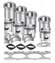
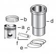
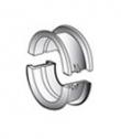
约翰迪尔 6068T/H 6.8T/H 活塞(米)RE515037 排放 2 & 3
|
|
|
发动机和设备型号
|
孔径:
4.19 in 106.5 mm
销径 Ø:
1.6250 in (+/- .0002) = 41mm
|
|
|
强鹿JOHN DEERE柴油机配件、发动机配件、发电机组:
C085003、C085004、ECB105012、C105003、AF1913、AF4539、C105004、RE533026、H0000351、ECC105017、C105003、ECC105028、ECC065003、B125003、ECB125011test note: for wiring&theory of operation information, see t4 - analog throttle (a) input low supporting information 1. ignition off 2. remove jumper wire between the two terminals 3. ignition on, engine off 4. using a multimeter, measure the voltage between the throttle (a) ground terminal and the 5 v supply terminal in the sen*** harness connector 4.0 - 6.0 v: open in analog throttle (a) input circuit or short to ground in analog throttle (a) input circuit or faulty ecu connection or faulty ecu below 4.0 v: open in analog throttle (a) 5 v supply circuit or short to ground in analog throttle (a) 5 v supply circuit or faulty ecu connection or faulty ecu ctm188 (20mar01) 04-160-40 powertech 10.5 l & 12.5 l level 6 fuel system 032001 pn=228 trouble code diagnostics&tests 04 160 41 ctm188 (20mar01) 04-160-41 powertech 10.5 l & 12.5 l level 6 fuel system 032001 pn=229 trouble code diagnostics&tests 04 160 42 dpsg,rg40854,296 –19–26aug99–1/1 level 6 ecu - t5 - analog throttle (b) input high rg10403 –19–19dec00 note: wiring diagram shows oem engine applications. for wiring information non-oem engines, refer to machine manual. analog throttle position sen*** ? the analog throttle position sen*** is a variable resistor (potentiometer) used to measure the position of the throttle. the throttle input voltage normally varies between 1.0&4.0 volts depending on throttle position. analog throttle voltage at low idle will be approximately 1.0 volt&4.0 volts at high idle. note: the ecu has the ability to learn different voltages for low&high idle, so the voltages above may change depending on application. this code will set if: ? the analog throttle input voltage exceeds 4.75 volts. the voltage is higher than what is physically possible for the throttle lever to achieve. if this code sets, the following will occur: ? if more than one throttle is available, the ecu will ignore the input from the analog throttle,&will use the input values from another throttle. ? if the analog throttle is the only throttle/all additional throttles are also faulted, the ecu will use a default “limp-home” throttle value that will only allow idle engine speed. ctm188 (20mar01) 04-160-42 powertech 10.5 l & 12.5 l level 6 fuel system 032001 pn=230 trouble code diagnostics&tests ouo1004,0000c7f –19–08jan01–1/1 level 6 ecu - t5 - analog throttle (b) input high - continued – – –1/1 level 6 ecu - t5 - analog throttle (b) input high diagnostic procedure note: before using this diagnostic procedure, perform a preliminary inspection of 60-way ecu connector&the analog throttle (b) sen*** connector looking for dirty, damaged,/poorly positioned terminals. 04 160 43 – – –1/1 1 intermittent fault test note: for wiring&theory of operation information, see t5 - analog throttle (b) input high supporting information 1. ignition on, engine off 2. analog throttle (b) in the idle position 3. using the dst, read the analog throttle (b) voltage parameter 4.75 v/greater: go to 3 below 4.75 v: go to 2 – – –1/1 2 throttle travel voltage test note: for wiring&theory of operation information, see t5 - analog throttle (b) input high supporting information using the dst, read the analog throttle (b) voltage parameter while slowly operating the analog throttle (b) through full travel goes above 4.75 v: faulty analog throttle (b) sen*** connector or open in analog throttle (b) sen*** ground circuit or faulty analog throttle (b) sen*** never goes above 4.75 v: problem is intermittent. if no other codes are present, see intermittent fault diagnostics, earlier in this group ctm188 (20mar01) 04-160-43 powertech 10.5 l & 12.5 l level 6 fuel system 032001 pn=231 trouble code diagnostics&tests – – –1/1 3 throttle position input shorted test note: for wiring&theory of operation information, see t5 - analog throttle (b) input high supporting information 1. ignition off 2. disconnect analog throttle (b) sen*** connector 3. ignition on, engine off 4. using the dst, read the analog throttle (b) voltage parameter 0.25 v/less: go to 4 above 0.25 v: short to voltage in analog throttle (b) input circuit or faulty ecu 04 160 44 – – –1/1 4 throttle position ground circuit open test note: for wiring&theory of operation information, see t5 - analog throttle (b) input high supporting information 1. ignition off 2. analog throttle (b) sen*** connector disconnected 3. using a test light connected to battery (+), probe the ground terminal in analog throttle (b) sen*** harness connector light on: faulty analog throttle (b) sen*** connector or faulty analog throttle (b) sen*** light off: open in analog throttle (b) ground circuit ctm188 (20mar01) 04-160-44 powertech 10.5 l & 12.5 l level 6 fuel system 032001 pn=232 trouble code diagnostics&tests 04 160 45 ctm188 (20mar01) 04-160-45 powertech 10.5 l & 12.5 l level 6 fuel system 032001 pn=233 trouble code diagnostics&tests 04 160 46 dpsg,rg40854,297 –19–26aug99–1/1 level 6 ecu - t6 - analog throttle (b) input low rg10403 –19–19dec00 note: wiring diagram shows oem engine applications. for wiring information non-oem engines, refer to machine manual. analog throttle position sen*** ? the analog throttle position sen*** is a variable resistor (potentiometer) used to measure the position of the throttle. the throttle input voltage normally varies between 1.0&4.0 volts depending on throttle position. analog throttle voltage at low idle will be approximately 1.0 volt&4.0 volts at high idle. note: the ecu has the ability to learn different voltages for low&high idle, so the voltages above may change depending on application. this code will set if: ? the analog throttle input voltage drops below the minimum threshold. the voltage is lower than what is physically possible for the throttle lever to achieve. if this code sets, the following will occur: ? if more than one throttle is available, the ecu will ignore the input from the analog throttle,&will use the input values from another throttle. ? if the analog throttle is the only throttle/all additional throttles are also faulted, the ecu will use a default “limp-home” throttle value that will only allow idle engine speed. ctm188 (20mar01) 04-160-46 powertech 10.5 l & 12.5 l level 6 fuel system 032001 pn=234 trouble code diagnostics&tests ouo1004,0000c80 –19–08jan01–1/1 level 6 ecu - t6 - analog throttle (b) input low - continued – – –1/1 level 6 ecu - t6 - analog throttle (b) input low diagnostic procedure note: before using this diagnostic procedure, perform a preliminary inspection of 60-way ecu connector&the analog throttle (b) sen*** connector looking for dirty, damaged,/poorly positioned terminals. 04 160 47 – – –1/1 1 intermittent fault test note: for wiring&theory of operation information, see t6 - analog throttle (b) input low supporting information 1. ignition on, engine off 2. analog throttle (b) in the idle position 3. using the dst, read the analog throttle (b) voltage parameter 0.25 v/less: go to 3 above 0.25 v: go to 2 – – –1/1 2 throttle travel voltage test note: for wiring&theory of operation information, see t6 - analog throttle (b) input low supporting information using the dst, read the analog throttle (b) voltage parameter while slowly operating the analog throttle (b) through full travel goes below 0.25 v: faulty analog throttle (b) sen*** connector or open in analog throttle (b) sen*** ground circuit or faulty analog throttle (b) sen*** never goes below 0.25 v: problem is intermittent. if no other codes are present, see intermittent fault diagnostics, earlier in this group. ctm188 (20mar01) 04-160-47 powertech 10.5 l & 12.5 l level 6 fuel system 032001 pn=235 trouble code diagnostics&tests – – –1/1 3 throttle position wiring test note: for wiring&theory of operation information, see t6 - analog throttle (b) input low supporting information 1. ignition off 2. disconnect analog throttle (b) sen*** connector 3. install a jumper wire between the 5 v supply terminal&the input terminal in the harness side of the sen*** connector 4. ignition on, engine off 5. using the dst, read the analog throttle (b) voltage parameter below 4.75 v: go to 4 4.75 v/greater: faulty analog throttle (b) sen*** connector or faulty analog throttle (b) sen*** 04 160 48 – – –1/1 4 throttle position 5 v supply test note: for wiring&theory of operation information, see t6 - analog throttle (b) input low supporting information 1. ignition off 2. remove jumper wire between the two terminals 3. ignition on, engine off 4. using a multimeter, measure the voltage between the throttle ground terminal and the 5 v supply terminal in the sen*** harness connector 4.0 - 6.0 v: open in analog throttle (b) input circuit or short to ground in analog throttle (b) input circuit or faulty ecu connection or faulty ecu below 4.0 v: open in analog throttle (b) 5 v supply circuit or short to ground in analog throttle (b) 5 v supply circuit or faulty ecu connection or faulty ecu ctm188 (20mar01) 04-160-48 powertech 10.5 l & 12.5 l level 6 fuel system 032001 pn=236 trouble code diagnostics&tests 04 160 49 ctm188 (20mar01) 04-160-49 powertech 10.5 l & 12.5 l level 6 fuel system 032001 pn=237 trouble code diagnostics&tests 04 160 50 dpsg,rg40854,209 –19–29jun99–1/1 level 6 ecu - t7 - can throttle invalid rg10656 –19–19dec00 note: for more can throttle wiring information, refer to machine manual. important: do not force probes into connector terminals/damage will result. use jt07328 connector adapter test kit to make measurements in connectors. this will ensure that terminal damage does not occur. can (controller area network) throttle ? can (controller area network) throttle is information sent to the ecu by another controller over can of the desired throttle position. this code will set if: ? the ecu either does not receive throttle information over can,/the information received is not valid. if this code sets, the following will occur: ? if more than one throttle is available, the ecu will ignore the input from the can throttle,&will use the input values from another throttle. ? if the can throttle is the only throttle/all additional throttles are also faulted, the ecu will use a default “limp-home” throttle value that will only allow idle engine speed. ctm188 (20mar01) 04-160-50 powertech 10.5 l & 12.5 l level 6 fuel system 032001 pn=238 trouble code diagnostics&tests ouo1004,0000c81 –19–08jan01–1/1 level 6 ecu - t7 - can throttle invalid - continued – – –1/1 level 6 ecu - t7 - can throttle invalid diagnostic procedure note: before using this diagnostic procedure, perform a preliminary inspection of 60-way ecu connector looking for dirty, damaged,/poorly positioned terminals. 04 160 51 – – –1/1 1 intermittent fault test note: for wiring&theory of operation information, see t7 - can throttle invalid supporting information. 1. ignition on, engine off 2. using the dst, monitor dtcs on the active code display parameter 3. make note of any dtcs, then clear all dtcs 4. ignition on, engine running 5. using the dst, monitor dtcs on the active code display parameter spn 91 fmi 9 reoccurs: go to 2 spn 91 fmi 9 doesn’t reoccur: problem is intermittent. if no other codes are present, see intermittent fault diagnostics, earlier in this group. – – –1/1 2 application related dtcs test note: for wiring&theory of operation information, see t7 - can throttle invalid supporting information. check other controllers on application for can related dtcs if application has other controllers communicating on can bus. no can related dtcs found on other controllers: go to 3 can related dtcs on other controllers found: refer to diagnostic procedures for controller. repair cause of throttle related dtc&retest. – – –1/1 3 resistance between can high&low test note: for wiring&theory of operation information, see t7 - can throttle invalid supporting information. 1. ignition off 2. using a multimeter, measure resistance between terminals c&d in the harness end of the diagnostic connector between 45 - 75 ohms: go to 4 less than 45/greater than 75 ohms: faulty/missing can terminator connector(s) or open/short in can wiring harness ctm188 (20mar01) 04-160-51 powertech 10.5 l & 12.5 l level 6 fuel system 032001 pn=239 trouble code diagnostics&tests 04 160 52 – – –1/1 4 can wiring shorted to ground/voltage test note: for wiring&theory of operation information, see t7 - can throttle invalid supporting information. 1. ignition on 2. using a multimeter, measure voltage between a good chassis ground and: ? terminal c in the diagnostic connector ? terminal d in the diagnostic connector both measurements between 1.5 - 3.5 v: faulty ecu connector or other connector in the can system or faulty ecu either measurement less than 1.5 v or greater than 2.5 v: can wiring shorted to ground/voltage or another controller in the can system faulty or faulty ecu ctm188 (20mar01) 04-160-52 powertech 10.5 l & 12.5 l level 6 fuel system 032001 pn=240 trouble code diagnostics&tests 04 160 53 ctm188 (20mar01) 04-160-53 powertech 10.5 l & 12.5 l level 6 fuel system 032001 pn=241 trouble code diagnostics&tests 04 160 54 dpsg,rg40854,294 –19–26aug99–1/1 level 6 ecu - t8 - pwm throttle input high rg10404 –19–20dec00 note: for more pwm throttle wiring information, refer to machine manual. important: do not force probes into connector terminals/damage will result. use jt07328 connector adapter test kit to make measurements in connectors. this will ensure that terminal damage does not occur. pwm (pulse width modulated) throttle position input ? the pwm throttle signal is sent to the ecu by the chassis computer. the pwm signal is a square wave signal with a constant frequency. the pulse-width of the signal (amount of time the signal is high) varies as throttle input from the chassis computer varies. this code will set if: ? the pulse-width of the pwm signal is greater than the normal operating range of the signal. if this code sets, the following will occur: ? if more than one throttle is available, the ecu will ignore the input from the pwm throttle,&will use the input values from another throttle. ? if the pwm throttle is the only throttle/all additional throttles are also faulted, the ecu will use a default “limp-home” throttle value that will only allow idle engine speed. ctm188 (20mar01) 04-160-54 powertech 10.5 l & 12.5 l level 6 fuel system 032001 pn=242 trouble code diagnostics&tests ouo1004,0000c82 –19–08jan01–1/1 level 6 ecu - t8 - pwm throttle input high - continued – – –1/1 level 6 ecu - t8 - pwm throttle input high diagnostic procedure note: before using this diagnostic procedure, perform a preliminary inspection of 60-way ecu connector&the throttle sen*** connector looking for dirty, damaged,/poorly positioned terminals. 04 160 55 – – –1/1 1 intermittent fault test note: for wiring&theory of operation information, see t8 - pwm throttle input high supporting information 1. ignition on, engine off 2. using the dst, monitor dtcs on the active code display parameter 3. make note of any dtcs, then clear all dtcs 4. ignition on, engine running 5. using the dst, monitor dtcs on the active code display parameter spn 91 fmi 3 reoccurs: go to 2 spn 91 fmi 3 doesn’t reoccur: problem is intermittent. if no other codes are present, see intermittent fault diagnostics, earlier in this group. – – –1/1 2 application related dtcs test note: for wiring&theory of operation information, see t8 - pwm throttle input high supporting information check other controllers on application for related dtcs if pwm throttle signal originates from another controller other controllers report no throttle related dtcs: go to 3 other controllers do report a throttle related dtc: refer to diagnostic procedures for controller. repair cause of throttle related dtc&retest. – – –1/1 3 open in pwm signal wire test note: for wiring&theory of operation information, see t8 - pwm throttle input high supporting information 1. ignition off 2. disconnect 60 way-ecu connector 3. obtain wiring information for this application&determine the source of the pwm throttle signal 4. disconnect the connector that outputs the pwm throttle signal 5. using a multimeter, measure the resistance between terminal j1 of the 60-way ecu connector&terminal of originating pwm throttle signal 5 ohms/less: go to 4 greater than 5 ohms: open in pwm throttle signal wire ctm188 (20mar01) 04-160-55 powertech 10.5 l & 12.5 l level 6 fuel system 032001 pn=243 trouble code diagnostics&tests – – –1/1 4 short in pwm circuit test note: for wiring&theory of operation information, see t8 - pwm throttle input high supporting information 1. ignition off 2. 60-way ecu connector&the other signal source controller still disconnected 3. using a multimeter measure resistance between terminal j1 in the harness end of the 60-way ecu connector and: ? all other terminals in that connector ? a good chassis ground all measurements greater than 2000 ohms: go to 5 any measurement less than 2000 ohms: short in pwm circuit 04 160 56 – – –1/1 5 pwm throttle source controller connector test note: for wiring&theory of operation information, see t8 - pwm throttle input high supporting information 1. ignition off 2. 60-way ecu connector still disconnected 3. reconnect pwm signal source connector 4. ignition on 5. using a multimeter, measure voltage while operating the throttle between terminal j1 in the harness end of the 60-way ecu connector&a good chassis ground between 0.5 v&4.8v: faulty pwm signal source controller or wrong ecu for the vehicle or faulty ecu connector or faulty ecu less than 0.5 v or greater than 4.8v: faulty pwm throttle signal source controller connector or faulty pwm throttle signal source controller ctm188 (20mar01) 04-160-56 powertech 10.5 l & 12.5 l level 6 fuel system 032001 pn=244 trouble code diagnostics&tests 04 160 57 ctm188 (20mar01) 04-160-57 powertech 10.5 l & 12.5 l level 6 fuel system 032001 pn=245 trouble code diagnostics&tests 04 160 58 dpsg,rg40854,295 –19–26aug99–1/1 level 6 ecu - t9 - pwm throttle input low rg10404 –19–20dec00 note: for more pwm throttle wiring information, refer to machine manual. important: do not force probes into connector terminals/damage will result. use jt07328 connector adapter test kit to make measurements in connectors. this will ensure that terminal damage does not occur. pwm (pulse width modulated) throttle position input ? the pwm throttle signal is sent to the ecu by the chassis computer. the pwm signal is a square wave signal with a constant frequency. the pulse-width of the signal (amount of time the signal is high) varies as throttle input from the chassis computer varies. this codes will set if: ? the ecu senses that the pulse-width of the pwm signal is lower than the normal operating range of the signal. if this code sets, the following will occur: ? if more than one throttle is available, the ecu will ignore the input from the pwm throttle,&will use the input values from another throttle. ? if the pwm throttle is the only throttle/all additional throttles are also faulted, the ecu will use a default “limp-home” throttle value that will only allow idle engine speed. ctm188 (20mar01) 04-160-58 powertech 10.5 l & 12.5 l level 6 fuel system 032001 pn=246 trouble code diagnostics&tests ouo1004,0000c83 –19–08jan01–1/1 level 6 ecu - t9 - pwm throttle input low - continued – – –1/1 level 6 ecu - t9 - pwm throttle input low diagnostic procedure note: before using this diagnostic procedure, perform a preliminary inspection of 60-way ecu connector&the throttle sen*** connector looking for dirty, damaged,/poorly positioned terminals. 04 160 59 – – –1/1 1 intermittent fault test note: for wiring&theory of operation information, see t9 - pwm throttle input low supporting information 1. ignition on, engine off 2. using the dst, monitor dtcs on the active code display parameter 3. make note of any dtcs, then clear all dtcs 4. ignition on, engine running 5. using the dst, monitor dtcs on the active code display parameter spn 91 fmi 4 reoccurs: go to 2 spn 91 fmi 4 doesn’t reoccur: problem is intermittent. if no other codes are present, see intermittent fault diagnostics, earlier in this group. – – –1/1 2 application related dtcs test note: for wiring&theory of operation information, see t9 - pwm throttle input low supporting information check other controllers on application for related dtcs if pwm throttle signal originates from another controller other controllers report no throttle related dtcs: go to 3 other controllers do report a throttle related dtc: refer to diagnostic procedures for controller. repair cause of throttle related dtc&retest – – –1/1 3 open in pwm signal wire test note: for wiring&theory of operation information, see t9 - pwm throttle input low supporting information 1. ignition off 2. disconnect 60 way-ecu connector 3. obtain wiring information for this application&determine the source of the pwm throttle signal 4. disconnect the connector that outputs the pwm throttle signal 5. using a multimeter, measure the resistance between terminal j1 of the 60-way ecu connector&terminal of originating pwm throttle signal 5 ohms/less: go to 4 greater than 5 ohms: open in pwm throttle signal wire ctm188 (20mar01) 04-160-59 powertech 10.5 l & 12.5 l level 6 fuel system 032001 pn=247 trouble code diagnostics&tests – – –1/1 4 short in pwm circuit test note: for wiring&theory of operation information, see t9 - pwm throttle input low supporting information 1. ignition off 2. 60-way ecu connector&the other signal source controller still disconnected 3. using a multimeter measure resistance between terminal j1 in the harness end of the 60-way ecu connector and: ? all other terminals in that connector ? a good chassis ground all measurements greater than 2000 ohms: go to 5 any measurement less than 2000 ohms: short in pwm circuit 04 160 60 – – –1/1 5 pwm throttle source controller connector test note: for wiring&theory of operation information, see t9 - pwm throttle input low supporting information 1. ignition off 2. 60-way ecu connector still disconnected 3. reconnect pwm signal source connector 4. ignition on 5. using a multimeter, measure voltage while operating the throttle between terminal j1 in the harness end of the 60-way ecu connector&a good chassis ground between 0.5 v&4.8v: faulty pwm signal source controller or wrong ecu for the vehicle or faulty ecu connector or faulty ecu less than 0.5 v or greater than 4.8v: faulty pwm throttle signal source controller connector or faulty pwm throttle signal source controller ctm188 (20mar01) 04-160-60 powertech 10.5 l & 12.5 l level 6 fuel system 032001 pn=248 trouble code diagnostics&tests 04 160 61 ctm188 (20mar01) 04-160-61 powertech 10.5 l & 12.5 l level 6 fuel system 032001 pn=249 trouble code diagnostics&tests 04 160 62 dpsg,rg40854,171 –19–28jun99–1/1 level 6 ecu - t10 - pwm throttle abnormal pulse width rg10404 –19–20dec00 note: for more pwm throttle wiring information, refer to machine manual. important: do not force probes into connector terminals/damage will result. use jt07328 connector adapter test kit to make measurements in connectors. this will ensure that terminal damage does not occur. pwm (pulse width modulated) throttle position input ? the pwm throttle signal is sent to the ecu by the chassis computer. the pwm signal is a square wave signal with a constant frequency. the pulse-width of the signal (amount of time the signal is high) varies as throttle input from the chassis computer varies. this code will set if: ? the ecu senses that the frequency of the pwm signal is not within range. if this code sets, the following will occur: ? if more than one throttle is available, the ecu will ignore the input from the pwm throttle,&will use the input values from another throttle. ? if the pwm throttle is the only throttle/all additional throttles are also faulted, the ecu will use a default “limp-home” throttle value that will only allow idle engine speed. ctm188 (20mar01) 04-160-62 powertech 10.5 l & 12.5 l level 6 fuel system 032001 pn=250 trouble code diagnostics&tests ouo1004,0000c84 –19–08jan01–1/1 level 6 ecu - t10 - pwm throttle abnormal pulse width - continued – – –1/1 level 6 ecu - t10 - pwm throttle abnormal pulse width diagnostic procedure note: before using this diagnostic procedure, perform a preliminary inspection of 60-way ecu connector&the throttle sen*** connector looking for dirty, damaged,/poorly positioned terminals. 04 160 63 – – –1/1 1咸阳约翰迪尔曲轴位置传感器一级代理,安阳约翰迪尔R114282曲轴齿轮诚信推荐,邯郸JOHNDEERE喷油器诚信推荐,肇庆强鹿柴油机传感器RE167207厂家批发,岳阳JohnDeere气门油封RE529187批发价,海东强鹿柴油机曲轴代理商,常德JohnDeere张紧轮RE518097的价格,天水johndeere约翰迪尔水泵批发,赣州强鹿约翰迪尔喷油器SE501957一级代理,丽水JohnDeere发动机缸套R116397公司, intermittent fault test note: for wiring&theory of operation information, see t10 - pwm throttle abnormal pulse width supporting information 1. ignition on, engine off 2. using the dst, monitor dtcs on the active code display parameter 3. make note of any dtcs, then clear all dtcs 4. ignition on, engine running 5. using the dst, monitor dtcs on the active code display parameter spn 91 fmi 8 reoccurs: go to 2 spn 91 fmi 8 doesn’t reoccur: problem is intermittent. if no other codes are present, see intermittent fault diagnostics, earlier in this group. – – –1/1 2 application related dtcs test note: for wiring&theory of operation information, see t10 - pwm throttle abnormal pulse width supporting information check other controllers on application for related dtcs if pwm throttle signal originates from another controller other controllers report no throttle related dtcs: go to 3 other controllers do report a throttle related dtc: refer to diagnostic procedures for controller. repair cause of throttle related dtc&retest. – – –1/1 3 open in pwm signal wire test note: for wiring&theory of operation information, see t10 - pwm throttle abnormal pulse width supporting information 1. ignition off 2. disconnect 60 way-ecu connector 3. obtain wiring information for this application&determine the source of the pwm throttle signal 4. disconnect the connector that outputs the pwm throttle signal 5. using a multimeter, measure the resistance between terminal j1 of the 60-way ecu connector&terminal of originating pwm throttle signal 5 ohms/less: go to 4 greater than 5 ohms: open in pwm throttle signal wire ctm188 (20mar01) 04-160-63 powertech 10.5 l & 12.5 l level 6 fuel system 032001 pn=251 trouble code diagnostics&tests – – –1/1 4 short in pwm circuit test note: for wiring&theory of operation information, see t10 - pwm throttle abnormal pulse width supporting information 1. ignition off 2. 60-way ecu connector&the other signal source controller still disconnected 3. using a multimeter measure resistance between terminal j1 in the harness end of the 60-way ecu connector and: ? all other terminals in that connector ? a good chassis ground all measurements greater than 2000 ohms: go to 5 any measurement less than 2000 ohms: short in pwm circuit 04 160 64 – – –1/1 5 pwm throttle source controller connector test note: for wiring&theory of operation information, see t10 - pwm throttle abnormal pulse width supporting information 1. ignition off 2. 60-way ecu connector still disconnected 3. reconnect pwm signal source connector 4. ignition on 5. using a multimeter, measure voltage while operating the throttle between terminal j1 in the harness end of the 60-way ecu connector&a good chassis ground between 0.5 v&4.8v: faulty pwm signal source controller or wrong ecu for the vehicle or faulty ecu connector or faulty ecu less than 0.5 v or greater than 4.8v: faulty pwm throttle signal source controller connector or faulty pwm throttle signal source controller ctm188 (20mar01) 04-160-64 powertech 10.5 l & 12.5 l level 6 fuel system 032001 pn=252 trouble code diagnostics&tests 04 160 65 ctm188 (20mar01) 04-160-65 powertech 10.5 l & 12.5 l level 6 fuel system 032001 pn=253 trouble code diagnostics&tests 04 160 66 rg40854,0000004 –19–19dec00–1/1 level 6 ecu - t11 - excavator throttle reference voltage high rg11624 –19–19jan01 note: for more excavator throttle wiring information, refer to machine manual. important: do not force probes into connector terminals/damage will result. use jt07328 connector adapter test kit to make measurements in connectors. this will ensure that terminal damage does not occur. 450c lc excavator throttle ? the 450c lc excavator uses an analog throttle to measure throttle position. this throttle is connected to the pump&valve controller, which sends throttle input information to the ecu through a dedicated wire. since the ecu&pump&valve controller do not share a common ground, a throttle voltage reference wire&a throttle ground wire accompany the throttle input wire. the ecu calculates the differences in controller grounds in order to determine the throttle request by the pump and valve controller. this code will set if: ? the excavator throttle reference voltage to the ecu exceeds 4.2 volts. if this code sets, the following will occur: ? the ecu will default excavator throttle reference voltage to 3.75 volts. ctm188 (20mar01) 04-160-66 powertech 10.5 l & 12.5 l level 6 fuel system 032001 pn=254 trouble code diagnostics&tests ouo1004,0000c85 –19–08jan01–1/1 level 6 ecu - t11 - excavator throttle reference voltage high - continued – – –1/1 level 6 ecu - t11 - excavator throttle reference voltage high diagnostic procedure note: before using this diagnostic procedure, perform a preliminary inspection of 60-way ecu connector&the throttle sen*** connector looking for dirty, damaged,/poorly positioned terminals. 04 160 67 – – –1/1 1 intermittent fault test note: for wiring&theory of operation information, see t11 - excavator throttle reference voltage high supporting information 1. ignition on, engine off 2. using the dst, monitor dtcs on the active code display parameter 3. make note of any KEY PART NO. PART NAME QTY SERIAL NO. F F F REMARKS
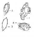
1 R67364 ELBOW FITTING 2 X
2 R51936 SEALING WASHER 6 X
3 RE66060 FUEL LINE 1 X
4 R135106 CLAMP 1 X 0.190" X 7/8"
5 RE501164 ANEROID LINE 1 X
6 R67271 UNION FITTING 1 X
7 28H1518 WASHER 1 X 0.493" X 0.675" X 5/16", 3/8" X 1"
8 19H1731 CAP SCREW 1 X
9 R121195 CAP SCREW 4 X
10 R121164 GEAR 1 X
11 R502143 PACKING 1 X
12 .. STUD 4 X OPTION 4604
13 M72490 WASHER 4 X
14 14H1090 NUT 4 X 3/8"
15 .. PACKING 1 X (ORDER RE503797 OR RE504827)
16 RE503797 FITTING 1 X
17 R51936 SEALING WASHER 1 X (USE WITH RE501162)
R505620 WASHER 1 X (USE WITH RE509547)
18 RE509547 ANEROID LINE 1 X (SUB FOR RE501162)
19 RE502650 FITTING 1 X
20 RE503803 FUEL PUMP 1 X (MOTORPAL)
21 SE500500 FUEL INJECTION PUMP 1 X (A)
22 RE501531 FUEL LINE 1 X (ALSO ORDER R51936)
(A)REMANUFACTURED
ECHANGE STANDARD
GENERAUEBERHOLT
RIGATTO
REFABRICADO POR
RENOVERAD
KEY PART NO. PART NAME QTY SERIAL NO. F F F REMARKS
1 RE507857 KIT 6 X
2 .. PACKING 1 X (ORDER RE503798 OR RE504827)
3 RE503798 CHECK VALVE 1 X
4 R502143 PACKING 1 X
5 .. PACKING 1 X (ORDER RE503797 OR RE504827)
6 RE503797 FITTING 1 X
7 .. PACKING 1 X (ORDER RE503796 OR RE504827)
8 RE503796 FITTING 1 X
9 19M7077 CAP SCREW 1 X M6 X 20
10 RE503799 KIT 1 X
11 RE504642 KIT 1 X
12 RE504828 KIT 1 X
13 R54025 WASHER 1 X
14 RE504827 O-RING KIT 1 X
KEY PART NO. PART NAME QTY SERIAL NO. F F F REMARKS
1 19M7077 CAP SCREW 1 X
2 RE503802 KIT 1 X 9/32" X 5/8" X 0.065"
3 24H1287 WASHER 7 X 1/4" X 1"
4 .. PACKING 1 X M6 X 20, (ORDER RE504827)
5 RE507602 KIT 1 X (24-VOLT)
6 R501483 BRACKET 1 X 11/32" X 11/16" X 0.065"
7 RE506963 SOLENOID 1 X (24-VOLT)
8 19M7861 SCREW 4 X
9 LG691620 COTTER PIN 1 X
10 19H1900 CAP SCREW 1 X
11 24H1136 WASHER 1 X
12 R78064 ELECTRICAL PLUG 3 X
13 R44302 TIE BAND 2 X
