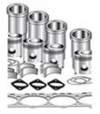
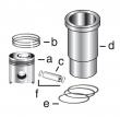
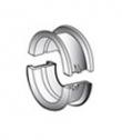
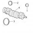
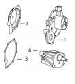
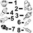
配件详情
强鹿JOHN DEERE柴油机配件、发动机配件、发电机组:
RE69781、RE50809、RE64243、RE507959、RE506544、RE504063、SE501235、RE504067、RE547892、AR2643、RE41956、RE539769、RE505475、SE500804、RE522964、AR2643、RE69791、SE501268、EDG-01V-H-1-PNT11-5115-R、A45-F-F-04-H
约翰迪尔挖掘装载机应用的发动机零件
设备型号 备注
300 O'rings on liner, Con Rod (m): T20007 R81410
300A O'rings on liner, Con Rod (m): T20007 R81410
300 O'rings on block, Con Rod (m): T20007, R81410, From ESN 154,766
300A O'rings on block, Con Rod (m): T20007, R81410, From ESN 154,766
300B O'rings on block, Con Rod (m): T20007, R81410, From ESN 154,766
301 O'rings on block, Con Rod (m): T20007, R81410, From ESN 154,766
301A O'rings on block, Con Rod (m): T20007, R81410, From ESN 154,766
302 Small pin, O'rings on liner, Con Rod (m): T20007, R81410, To ESN 179,601
302A Small pin, O'rings on liner, Con Rod (m): T20007, R81410, To ESN 179,601
302A Large pin, O'rings on block, Con Rod (m): RE19733 (SUB FOR AT18005), From ESN 179,602
310 Large pin, O'rings on block, Con Rod (m): RE19733 (SUB FOR AT18005), From ESN 179,602
301A Large pin, O'rings on block, Con Rod (m): RE19733 (SUB FOR AT18005), From ESN 179,602
302 Large pin, O'rings on block, Con Rod (m): RE19733 (SUB FOR AT18005), From ESN 179,602
400 O'rings on liner, Con Rod (m): RE19733 (SUB FOR AT18005), To ESN 158,257
400 Large pin, O'rings on block, Con Rod (m): RE19733 (SUB FOR AT18005), From ESN 158,258
401 Small pin, O'rings on block, Con Rod (m): T20007, R81410, To ESN 275,483
401A Small pin, O'rings on block, Con Rod (m): T20007, R81410, To ESN 275,483
410 Large pin, O'rings on block, Con Rod (m): R51727, R80034, From ESN 275,484
410B Large pin, O'rings on block, Con Rod (m): R51727, R80034, From ESN 275,484
310 Large pin, O'rings on block, Con Rod (m): R51727, R80034, From ESN 275,484
310B Large pin, O'rings on block, Con Rod (m): R51727, R80034, From ESN 275,484
401B Large pin, O'rings on block, Con Rod (m): R51727, R80034, From ESN 275,484
401C Large pin, O'rings on block, Con Rod (m): R51727, R80034, From ESN 275,484
401D Large pin, O'rings on block, Con Rod (m): R51727, R80034, From ESN 275,484
210C Con Rod (m): R80034, Piston (m): RE30250
310C Con Rod (m): R80034, Piston (m): RE30250
310D Con Rod (m): R80034, Piston (m): RE30250
315C Con Rod (m): R80034, Piston (m): RE30250
415B Con Rod (m): R80034, Piston (m): RE30250
415C Con Rod (m): R80034, Piston (m): RE30250
515B Con Rod (m): R80034, Piston (m): RE30250
310C Con Rod (m) R80032, R113612, R122191, Piston (m): RE33115
310D Con Rod (m) R80032, R113612, R122191, Piston (m): RE33115
315C Con Rod (m) R80032, R113612, R122191, Piston (m): RE33115
315D Con Rod (m) R80032, R113612, R122191, Piston (m): RE33115
515B Con Rod (m) R80032, R113612, R122191, Piston (m): RE33115
500 Block (m) R46350, R46430, R40910
500A Block (m) R46350, R46430, R40910
510 Block (m) R26160, R32020, R40850
500 Block (m) R26160, R32020, R40850
500A Block (m) R26160, R32020, R40850
500B Block (m) R26160, R32020, R40850
500C Block (m) R26160, R32020, R40850
500 Early power booster
500A Early power booster
500B Early power booster
500C Early power booster
510 Early power booster
500A Block (m) R40700, R47520, R48430, R50610, R72127
500B Block (m) R40700, R47520, R48430, R50610, R72127
500C Block (m) R40700, R47520, R48430, R50610, R72127
510 Block (m) R40700, R47520, R48430, R50610, R72127
410C Small pin
410C Large pin
410D Large pin
510B Large pin
410C (no special remarks)
410D (no special remarks)
510C (no special remarks)
610C (no special remarks)
310C Liter designated, Con Rod (m): R80034, Piston (m): RE30250, RE18697
310D Liter designated, Con Rod (m): R80034, Piston (m): RE30250, RE18697
315C Liter designated, Con Rod (m): R80034, Piston (m): RE30250, RE18697
315D Liter designated, Con Rod (m): R80034, Piston (m): RE30250, RE18697
515B Liter designated, Con Rod (m): R80034, Piston (m): RE30250, RE18697
210D Liter designated, Con Rod (m): R80034, Piston (m): RE30250, RE18697
310C Liter designated, Con Rod (m): R80032, R122191, R113612, Piston (m): RE19282, RE30250
315C Liter designated, Con Rod (m): R80032, R122191, R113612, Piston (m): RE19282, RE30250
315D Liter designated, Con Rod (m): R80032, R122191, R113612, Piston (m): RE19282, RE30250
515B Liter designated, Con Rod (m): R80032, R122191, R113612, Piston (m): RE19282, RE30250
300D Liter designated, Con Rod (m): R80032, R122191, R113612, Piston (m): RE19282, RE30250
410C Liter designated
410D Liter designated
510B Liter designated
410C Liter designated
410D Liter designated
510C Liter designated
510D Liter designated
610B Liter designated
610C Liter designated
110 84mm Bore Non Turbo
110 88mm Bore Non Turbo
710B Large pin, O'rings on block, Con Rod (m): RE16495, Piston (m): AR77762
710B Con Rod (m): R80032, R113612, Piston (m): RE22678, RE19278
710C Con Rod (m): R80032, R113612, Piston (m): RE22678, RE19278
600 Block (m) R40610, R40620, R45950, R47170, R48440
700 Con Rod (m) R35048, R58881, R40238, R66927, R53286
700A Con Rod (m) R35048, R58881, R40238, R66927, R53286
710B Liter designated, Con Rod (m): R80032, Piston (m): RE22678
710C Liter designated, Con Rod (m): R80032, Piston (m): RE22678
315SE Piston (m) RE59277, RE505100
535 Piston (m) RE515037 Tier 2 & Tier 3
315SG Piston (m) RE59277, RE505100
530B Piston (m) RE515037 Tier 2 & Tier 3
410E Piston (m) RE59277, RE505100
535 Piston (m) RE507758 Tier 2 & Tier 3
410G Piston (m) RE59277, RE505100
530B Piston (m) RE507758 Tier 2 & Tier 3
410J Piston (m) RE59277, RE505100
535 Piston (m) RE515037 Tier 2 & Tier 3
210LE Piston (m) RE59279, RE505101
120 Piston (m) RE55512, RE505102
530B Piston (m) RE515037 Tier 2 & Tier 3
310E Piston (m) RE59279, RE505101
710J Piston (m) RE527039 Tier 2 & Tier 3
310E Piston (m) RE59277, RE505100
710D Piston (m) RE55512, RE505102
310G Piston (m) RE59277, RE505100
710K Piston (m) RE527039 Tier 2 & Tier 3
310SE Piston (m) RE59277, RE505100
535 Piston (m) RE521616 Tier 2 & Tier 3
310SG Piston (m) RE59277, RE505100
530B Piston (m) RE521616 Tier 2 & Tier 3
麦克福斯约翰迪尔发动机零配件
|
发动机大修包
型号 数量 描述
TR114082 6 连杆衬套 PT 41 mm
TR119874 1 凸轮轴衬套
TR501124 12 连杆螺钉
TRE31617 12 气门密封 STEM LITER ENG
TRE44574 1 前油封
TRE505515 1 后油封
TRE532631 1 大修包
TRE536083 6 活塞缸套四配套,包括活塞,活塞环,活塞销,缸套,卡簧,阻水圈 (RE527039) 2V
TRE65165 6 主轴瓦(标准)
TRE65168 1 止推瓦(标准)
TRE65908 6 连杆瓦(标准
发动机内部修理套件
型号 数量 描述
TR114082 6 连杆衬套 PT 41 mm
TR119874 1 凸轮轴衬套
TR501124 12 连杆螺钉
TRE31617 12 气门密封 STEM LITER ENG
TRE44574 1 前油封
TRE505515 1 后油封
TRE532631 1 大修包
TRE536083 6 活塞缸套四配套,包括活塞,活塞环,活塞销,缸套,卡簧,阻水圈 (RE527039) 2V
TRE65165 6 主轴瓦(标准)
TRE65168 1 止推瓦(标准)
TRE65908 6 连杆瓦(标准)
|
|
|
约翰迪尔 6068T/H 6.8T/H 活塞(米)RE507758 排放 2 & 3
|
|
|
发动机和设备型号
|
孔径:
4.19 in 106.5 mm
销径 Ø:
1.6250 in (+/- .0002) = 41mm
发动机型号:
6068HF475
|
|
|
remove&install starter motor, group 100. remove fuel filter assemblies with mounting bases as required see replacing primary fuel filter/water separator in (lucas ecu controlled fuel system). ctm115, section 02, group 090. see replace final (secondary) fuel filter element in ctm115, section 02, group 090. remove fuel filter assemblies with mounting bases as required (john see replacing primary fuel filter/water separator in deere level 6 ecu controlled fuel system). ctm188, section 02, group 090 (dual rail fuel systems). see replace final (secondary) fuel filter element in ctm188, section 02, group 090 (dual rail fuel systems). see fuel filter/water separator assembly in ctm188, section 02, group 091 (single rail fuel systems). mount engine onto recommended safety approved repair stand. see mount engine onto repair stand in this group. remove fan, drive belts,&fan drive assembly. see group 070. remove alternator. see remove&install alternator in group 100. remove compres . see ctm67, oem engine acces ies. remove vibration damper&pulley assembly from crankshaft. see remove crankshaft vibration damper&pulley in group 040. disconnect all air intake/exhaust piping&turbocharger oil see remove turbocharger in group 080. inlet/drain lines. remove turbocharger. remove exhaust manifold&gaskets. see remove, inspect&install exhaust manifold in group 080. remove oil filter&oil filter housing. see remove oil filter&valve housing/oil cooler cover&valve housing in section 060. remove oil cooler assembly. see remove, clean&inspect engine oil cooler in group 060. remove coolant pump assembly. see remove coolant pump in group 070. remove water manifold/thermostat housing assembly. see remove&install thermostat housing in group 070. remove all six piston spray jets. see remove&install piston spray jets in group 030. (continued on next page) coolscan is a trademark of deere & company. oilscan is a registered trademark of deere & company. ctm100 (20mar01) 02-010-8 powertech 10.5 l & 12.5 l diesel engines 032001 pn=56 continued on next page engine rebuild guide, break-in&tune-up 02 010 9 rg,rg34710,50 –19–16oct00–2/3 engine disassembly sequence—continued procedure reference on 6105h&6125h engines, remove air intake manifold. see remove, inspect&install intake manifold in group 080. on 6105a&6125a engines, remove aftercooler assembly. see remove&install aftercooler assembly in group 080. remove fuel supply pump (lucas ecu controlled fuel system). see remove&install fuel supply pump in ctm115, section 02, group 090. remove fuel supply pump (john deere ecu controlled fuel system). see remove&install fuel supply pump in ctm188, section 02, group 090 (dual rail systems). see remove&install fuel supply pump in ctm188, section 02, group 091 (single rail systems). remove fuel manifold assembly on lucas ecu controlled fuel see remove&install fuel manifold in ctm 115, section systems. 02, group 090. remove fuel manifold assembly on john deere ecu controlled fuel see remove&install fuel manifold in ctm 188, section systems. 02, group 090 (dual rail fuel system). remove all remaining fuel lines, identify for reassembly in correct see ctm115, section 02, group 090/ctm188, section 02, group location. 090/091. remove engine oil pan. see remove engine oil pan in group 060. remove oil pickup tube. see remove&install oil pickup tube in group 060. remove front gear train access cover&timing gear cover. see remove timing gear cover in group 030. remove rocker arm cover. see remove&install rocker arm cover in group 020. note: identify valve train components&electronic unit injectors see remove rocker arm assembly in group 020. for reassembly in same location as removed. remove front&rear rocker arm&shaft assembly&eui wiring harness. remove electronic unit injectors on lucas ecu controlled fuel see remove&install electronic unit injectors in systems. ctm115, section 02, group 090. remove electronic unit injectors on john deere ecu controlled fuel see remove&install electronic unit injectors in systems. ctm188, section 02, group 090 (dual rail systems). see remove&install electronic unit injectors in ctm188, section 02, group 091 (single rail systems). remove camshaft gear&idler gear assembly. remove camshaft see remove&install camshaft in group 050. position sen &remove camshaft. remove oil pump drive gear&remove oil pump assembly. see remove engine oil pump in group 060. remove cylinder head&gasket. see remove cylinder head in group 020. remove flywheel. see remove flywheel in group 040. remove flywheel housing. see remove flywheel housing in group 040. remove rear crankshaft seal&seal housing. see remove rear crankshaft oil seal&housing assembly in group 040. (continued on next page) ctm100 (20mar01) 02-010-9 powertech 10.5 l & 12.5 l diesel engines 032001 pn=57 continued on next page engine rebuild guide, break-in&tune-up 02 010 10 rg,rg34710,50 –19–16oct00–3/3 engine disassembly sequence—continued procedure reference remove cylinder block front plate. see remove&install cylinder block front plate in group 030. perform wear checks on connecting rod bearing surfaces using see remove pistons&connecting rods in group 030. plastigage. remove piston&connecting rod assemblies. check crankshaft endplay. (see check crankshaft endplay in group 040.) remove main bearing caps with bearings. perform wear checks on see remove crankshaft main bearings in group 040. main bearing surfaces with plastigage. see check main bearing-to-journal oil clearance in group 040. remove crankshaft. see remove crankshaft in group 040. remove cylinder block plugs&serial number plate if block is to be see complete disassembly of cylinder block in group put in a hot tank. 030. inspect&repair individual components. see appropriate repair group. ctm100 (20mar01) 02-010-10 powertech 10.5 l & 12.5 l diesel engines 032001 pn=58 engine rebuild guide, break-in&tune-up 02 010 11 rg,rg34710,51 –19–16oct00–1/2 sealant application guidelines listed below are sealants which have been tested and are used by the john deere factory to control leakage and ensure hardware retention. always use the following recommended sealants when assembling your john deere diesel engine to ensure quality performance. loctite? thread sealants are designed to perform to sealing standards with machine oil residue present. if excessive machine oil/poor cleanliness quality exist, clean with solvent. refer to john deere merchandise and parts sales manual for ordering information. important: loctite? gasket materials are not designed to work with oil residue present. oil residues must be cleaned from surfaces before applying gasket material. loctite? 242 thread lock & sealer (medium strength) (blue): ty9370 6 ml (0.2 oz) tube ? threaded plugs&fittings: cylinder block (oil galley). ? cap screws: coolant pump, timing gear cover, camshaft gear access cover, oil pump. ? oil pressure sending unit. ? turbocharger oil inlet fitting. ? fuel filter check valve/elbow (filter header end) dual rail fuel system. ? piston spray jets. ? timing gear cover gasket&camshaft gear access cover gasket on earlier engines using fel-pro gaskets. ? idler gear carrier cap screws, camshaft gear retainer cap screws&fuel supply pump drive coupler cap screws. ? eui hold-down clamp cap screws. loctite? 271 thread lock & sealer (high strength) (clear): ty9371 6 ml (0.2 oz) tube ? oil filter adapter-to-base. loctite? 277 thread lock & sealer (high strength) (red): t43514 50 ml (1.7 oz) bottle ? expansion plugs in cylinder head&block. loctite? 台州JohnDeere温度传感器RE51774公司,七台河强鹿柴油机电子泵厂家供货,雅安JohnDeere气门锁夹T20077哪家好,郑州johndeere约翰迪尔强鹿柴油机热交换器厂家供货,泉州约翰迪尔6081发动机风扇皮带张紧轮价格行情,松原强鹿柴油机曲轴前油封RE54073供货商,克拉玛依约翰迪尔8320RT拖拉机发动机配件代理,玉树强鹿柴油发动机节恒温器一级代理,那曲约翰迪尔柴油机凸轮轴上衬套批发商,鄂尔多斯johndeere约翰迪尔强鹿柴油机涡轮增压器批发价,荆门强鹿发动机喷油器市场报价,呼和浩特JohnDeere曲轴RE504638厂家供应,邯郸约翰迪尔4039DF008机体批发,铁岭约翰迪尔强鹿4045柴油机曲轴齿轮一级代理,双鸭山JohnDeere强鹿凸轮随动件哪家好,宁德强鹿T20034凸轮轴下衬套价格,临汾强鹿发动机齿轮室哪里买,怒江JohnDeere连杆瓦R116081代理商,德阳约翰迪尔C110联合收割机柴油机配件市场报价,迪庆JohnDeere机油底壳垫片R532464价格行情,赣州强鹿约翰迪尔喷油器SE501957多少钱,郴州约翰迪尔AT21132止推轴承厂家供货,成都约翰迪尔联合收割机发动机进排气门代理商,白山约翰迪尔强鹿柴油滤芯re541922哪家买,景德镇约翰迪尔6090柴油机加大主轴瓦厂家供应,淄博约翰迪尔6081发动机连杆螺丝找哪家,漯河强鹿柴油机增压器RE509818哪里买,甘南JohnDeere喷油器RE543935厂家供应,济宁强鹿柴油机凸轮轴哪里买,玉树johndeere约翰迪尔强鹿柴油发动机发动机修理包RE527549批发价,大庆JohnDeere凸轮轴衬套RE521756厂家价格,拉萨强鹿6081柴油发动机曲轴齿轮市场报价,保山约翰迪尔6090柴油机缸套密封水圈代理商,石家庄约翰迪尔4045HCP29配件信息,巴彦淖尔强鹿约翰迪尔3029气缸盖螺丝代理,佛山约翰迪尔加大连杆瓦RE65908B批发价,揭阳强鹿6081发动机加大止推轴承瓦多少钱,白银美国JohnDeere曲轴瓦RE65165厂家价格,钦州JohnDeere连杆RE535555一级代理,济宁强鹿RE27349连杆瓦价格,河源强鹿滤芯AT18649T供货商,内江强鹿连杆RE500608价格,吴忠强鹿原装进口汽缸垫厂家价格,台州约翰迪尔强鹿机油冷却器AR55394哪家买,湘潭JOHNDEERE强鹿6068TF250配件厂家供货,武汉美国强鹿发动机大修包厂家供货,东营强鹿柴油滤芯RE532952价格行情,防城港强鹿油机冷却水泵RE546906信息,哈尔滨约翰迪尔4045柴油机止推轴承RE65912厂家供货,漯河约翰迪尔7030拖拉机发动机配件代理,清远强鹿大修包RE64294供应商,盘锦强鹿6068柴油机衬垫套厂家批发,阿坝强鹿6081柴油机节温器多少钱,宜春强鹿消防柴油机配件厂家批发,固原约翰迪尔发动机凸轮轴批发价,宝鸡强鹿6068柴油机传感器一级代理,淮安平衡轴铜套约翰迪尔4045柴油机代理,那曲强鹿活塞环RE539642诚信推荐,徐州JohnDeere连杆螺丝价格,天水约翰迪尔连杆R80032价格,上海强鹿6068缸套公司,台州JohnDeere温度传感器RE51774供货商,盐城约翰迪尔强鹿机油底壳垫片哪家好,西宁约翰迪尔四配套IK526727哪家买,515 flexible sealant (general purpose) (purple): ty6304 50 ml (1.7 oz) bottle ? timing gear cover&camshaft gear access cover gasket on earlier engines using fel-pro gasket. loctite? 592 pipe sealant with teflon? (white): ty9374 6 ml (0.2 oz) tube ? pipe plugs: cylinder block (water manifold), thermostat housing, air intake manifold,&coolant pump. ? temperature sending unit. ? coolant heater. ? oil pan drain valve/hose. loctite? 680 maximum strength retaining compound (green): ty15969 6 ml (0.2 oz) tube ? crankshaft flange&id of front wear sleeve for front&rear oil seal/wear sleeve installation. ? steel cup plugs on cylinder head&block. loctite is a registered trademark of loctite corp. teflon is a registered trademark of the du pont company ctm100 (20mar01) 02-010-11 powertech 10.5 l & 12.5 l diesel engines 032001 pn=59 continued on next page engine rebuild guide, break-in&tune-up 02 010 12 rg,rg34710,51 –19–16oct00–2/2 pt569 never-seez? compound pt569 227 g (8 oz) brush pt506 453 g (16 oz) spray ? cap screws: exhaust manifold, intake manifold, aftercooler, turbocharger oil return line, and turbocharger cap screws/nut. loctite? 222 small screw threadlocker (removable) (purple) ty24311 0.5 ml (0.02 oz) tube ? eui solenoid terminal nuts. loctite? 17430 high flex form-in-place gasket t43514 50 ml (1.7 oz) bottle ? oil pan-to-cylinder block (timing gear cover&rear seal housing t-joints). loctite? 7649, ty16285 clean-and-cure primer ? clean mating gasket surfaces on timing gear cover, camshaft gear access cover, oil pan,&block sealing surfaces. loctite is a registered trademark of loctite corp. never-seez is a registered trademark of the emhart chemical group. ctm100 (20mar01) 02-010-12 powertech 10.5 l & 12.5 l diesel engines 032001 pn=60 engine rebuild guide, break-in&tune-up 02 010 13 rg,rg34710,52 –19–02jan01–1/3 6105&6125 engine assembly sequence the following assembly sequence is suggested when engine has been completely disassembled. be sure to check runout, clearance,&all critical physical part specifications prior to assembling engine. replace parts as necessary&tighten retaining hardware to specifications given. refer to the appropriate repair group when assembling engine. important: always replace vibration damper whenever crankshaft is replaced or after a major engine overhaul. engine assembly sequence procedure reference install all plugs in cylinder block that were removed to service see complete disassembly of cylinder block in group cylinder block. 030. important: if new piston&liner kits are being installed, see install cylinder liners in group 030. install them as an assembly after crankshaft has been installed. install cylinder liners without o-rings&measure liner stand-out. install liners with packing. install crankshaft. see install crankshaft in group 040. install main bearings. see install main bearing inserts in block in group 040. rotate crankshaft by hand to ensure correct assembly. check see check crankshaft endplay in group 040. crankshaft endplay. install pistons&connecting rods. rotate crankshaft by hand to see in install pistons&connecting rods in group 030. ensure correct assembly. install crankshaft rear oil seal housing. see install crankshaft rear oil seal housing in group 040. install rear oil seal&wear sleeve assembly. see install crankshaft rear oil seal&wear sleeve in group 040. install flywheel. see install flywheel in group 040. install flywheel housing. see remove&install flywheel housing in group 040. install cylinder block front plate. see remove&install cylinder block front plate in group 030. install engine oil pump&drive gear. see install engine oil pump in group 060. install cylinder head using a new gasket. see install cylinder head in group 020. install camshaft&camshaft drive gear. see remove&install camshaft in group 050. install timing gear cover. see install timing gear cover in group 040. install oil pickup tube. see remove&install oil pickup tube in group 060. install engine oil pan. see install engine oil pan in group 060. install idler gear. pin camshaft&crankshaft. adjust idler see adjust front timing gear backlash in group 050. gear-to-camshaft gear&idler gear-to-oil pump gear backlash. install new crankshaft vibration damper&pulley assembly (with oil see install crankshaft vibration damper&front seal). oil seal in group 040. (continued on next page) ctm100 (20mar01) 02-010-13 powertech 10.5 l & 12.5 l diesel engines 032001 pn=61 continued on next page engine rebuild guide, break-in&tune-up 02 010 14 rg,rg34710,52 –19–02jan01–2/3 engine assembly sequence—continued procedure reference install electronic unit injectors on lucas ecu controlled fuel systems. see remove&install electronic unit injectors in ctm115, section 02, group 090. install electronic unit injectors on john deere ecu controlled fuel see remove&install electronic unit injectors in systems. ctm188, section 02, group 090 (dual rail systems). see remove&install electronic unit injectors in ctm188, section 02, group 091 (single rail systems). install valve bridges&push tubes. install front&rear rocker arm see install rocker arm assembly in group 020. shaft assemblies. install eui wiring harness. preload unit injectors&adjust valve clearance. see check&adjust valve assembly clearances and injector preload in group 020. install front camshaft gear access cover. see install timing gear cover in group 040. install fuel supply pump (lucas ecu controlled fuel system). see remove&install fuel supply pump in ctm115, section 02, group 090. install fuel supply pump (john deere ecu controlled fuel system). see remove&install fuel supply pump in ctm188, section 02, group 090 (dual rail systems). see remove&install fuel supply pump in ctm188, section 02, group 091 (single rail systems). install fuel manifold assembly on lucas ecu controlled fuel systems. see remove&install fuel manifold in ctm 115, section 02, group 090. install fuel manifold assembly on john deere ecu controlled fuel see remove&install fuel manifold in ctm 188, section systems. 02, group 090 (dual rail fuel system). install all remaining fuel lines, identify for reassembly in correct see ctm115, section 02, group 090/ctm188, section 02, group location. 090/091. on 6105h&6125h engines, install air intake manifold. see remove, inspect&install intake manifold in group 080. on 6105a engines, install aftercooler assembly. see remove&install aftercooler assembly in group 080. install fuel filter assemblies with mounting bases as required (lucas see replacing primary fuel filter/water separator in ecu controlled fuel system). ctm115, section 02, group 090. see replace final (secondary) fuel filter element in ctm115, section 02, group 090. install fuel filter assemblies with mounting bases as required (john see replacing primary fuel filter/water separator in deere level 6 ecu controlled fuel system). ctm188, section 02, group 090 (dual rail fuel systems). see replace final (secondary) fuel filter element in ctm188, section 02, group 090 (dual rail fuel systems). see fuel filter/water separator assembly in ctm188, section 02, group 091 (single rail fuel systems). install all six piston spray jets. see remove&install piston spray jets in group 030. install coolant pump assembly. see install coolant pump in group 070. (continued on next page) ctm100 (20mar01) 02-010-14 powertech 10.5 l & 12.5 l diesel engines 032001 pn=62 continued on next page engine rebuild guide, break-in&tune-up 02 010 15 rg,rg34710,52 –19–02jan01–3/3 engine assembly sequence—continued procedure reference install water manifold/thermostat housing assembly. see remove&install thermostat housing in group 070. install oil filter housing/oil cooler assembly. see install oil filter&valve housing/oil cooler cover&valve housing in section 060. install exhaust manifold assembly. see remove, inspect&install exhaust manifold in group 080. install turbocharger. connect all turbocharger oil lines&see install turbocharger in group 080. intake/exhaust piping. install alternator. see remove&install alternator in group 100. install compres . see ctm67, oem engine acces ies. install fan drive, fan&fan belt. see group 070. mount engine into vehicle. see vehicle repair manual. flush cooling system. fill engine systems with recommended fuel, see flush&service cooling system in section 01, lubricant,&coolant. group 002. perform engine break-in&normal standard performance checks. see perform engine break-in in this group. rg,rg34710,1053 –19–05dec00–1/1 engine break-in guidelines engine break-in should be performed after overhaul or when the following repairs have been made: main bearings, rod bearings, crankshaft,/any combination of these parts have been replaced. pistons, rings,/liners have been replaced. rear crankshaft oil seal&wear sleeve have been replaced. (primary objective is to see if oil seal still leaks). cylinder head has been removed. electronic unit injectors have been removed/critical adjustments have been made while they are on the engine. (primary objective of break-in is to check power). ctm100 (20mar01) 02-010-15 powertech 10.5 l & 12.5 l diesel engines 032001 pn=63 engine rebuild guide, break-in&tune-up 02 010 16 rg,100,jw7645 –19–05nov99–1/2 perform engine break-in important: if engine has a pto, break-in can be performed at the pto if it is done as specified below. to prevent possible damage to the pto gear box, do not apply full load through the pto for any longer than the specified 10 minutes below. use a dynamometer to perform the following preliminary break-in procedure. if necessary, preliminary engine break-in can be performed without a dynamometer if under controlled operating conditions. important: do not use john deere plus-50 oil or engine oils meeting api cg4, api cf4, acea e3/acea e2, performance levels during break-in period of an engine that has had a major overhaul. these oils will not allow an overhauled engine to properly wear during the break-in period. do not add makeup oil until the oil level is below the add mark. john deere break-in oil should be used to make up any oil consumed during break-in period. do not fill above the crosshatch pattern/full mark. oil levels anywhere within the crosshatch are acceptable. 1. fill engine crankcase to proper level with john deere engine break-in oil during break-in operation. use break-in oil regardless of ambient temperature. this oil is specifically formulated to enhance break-in of john deere diesel engines. under normal conditions, do not exceed 100 hours with break-in oil. if john deere engine break-in oil is not available, use diesel engine oil meeting api service classification ce/acea specification e1. important: during preliminary break-in, periodically check engine oil pressure&coolant temperature. also check for signs of fuel, oil, or coolant leaks. 2. start engine, run at loads&speeds shown in following chart for time limits given. preliminary engine break-in after major overhaul time load engine speed 1 minute no load 850 rpm 2 minutes no load fast idle 10 minutes 1/2—3/4 load 2000 rpm to rated speed 10 minutes full load rated speed 3. after preliminary break-in, run engine 1—2 minutes at 1500 rpm, with no load before shut-down. 4. check&readjust valve clearance as necessary. cylinder head retorque is not required. note: during the first 20 hours, avoid prolonged periods of engine idling/sustained maximum load operation. if engine will idle longer than 5 minutes, stop engine. 5. operate the engine at heavy loads with minimal idling during the break-in period. if the engine has significant operating time at idle, constant speeds, and/or light load usage, an additional 100 hour break-in period is recommended using a new change of john deere engine break-in oil and new john deere oil filter. ctm100 (20mar01) 02-010-16 powertech 10.5 l & 12.5 l diesel engines 032001 pn=64 continued on next page engine rebuild guide, break-in&tune-up 02 010 17 rg,100,jw7645 –19–05nov99–2/2 check engine oil level more frequently during engine break-in period. as a general rule, makeup oil should not need to be added during 100-hour break-in period. however, if makeup oil is required in the first 100-hour break-in, an additional 100-hour break-in period is required. use a new change of john deere engine break-in oil&a new john deere oil filter. after 100 hours maximum, drain break-in oil and change oil filter. fill crankcase with john deere torq-gard supreme?/plus-50?/other heavy-duty diesel engine oil within the same service classification as recommended in this manual. see diesel engine oil in group 002, fuels, lubricants, and coolant. note: some increase in oil consumption may be expected when low viscosity oils are used. check oil levels more frequently. if air temperature is below -10° c (14° f), use an engine block heater. torq-gard supreme is a registered trademark of deere & company. plus-50 is a registered trademark of deere & company. dpsg,ouo1004,919 –19–30jun99–1/1 check crankcase ventilation system rg10239 –un–09jul99 a—crankcase vent tube crankcase vent tube 1. inspect crankcase ventilation system for restrictions. lack of ventilation causes sludge to form in crankcase. this can lead to clogging of oil passages, filters, and screens, resulting in serious engine damage. 2. clean crankcase vent tube (a) with solvent and compressed air if restricted. install&tighten hose clamps securely. ctm100 (20mar01) 02-010-17 powertech 10.5 l & 12.5 l 张家界JOHNDEERE强鹿6135HF475配件批发,鄂尔多斯强鹿柴油滤芯RE507284公司,福州约翰迪尔6081柴油机气门锁夹批发价,武汉美国强鹿发动机大修包多少钱,厦门约翰迪尔RE506428滤芯代理,中山约翰迪尔E360LC液压挖掘机发动机配件信息,揭阳约翰迪尔RE546336滤芯信息,杭州强鹿柴油机启动马达RE515895批发价,连云港johndeere约翰迪尔强鹿柴油机主轴瓦的价格,和田约翰迪尔RE501578修理包价格行情,西双版纳约翰迪尔后油封RE520036供应商,临汾约翰迪尔机油底壳垫片R123354批发价,巴音郭楞JohnDeereTel51774水温传感器找哪家,乐山约翰迪尔连杆铜套R114082哪家好,锡林郭勒强鹿柴油机皮带R135590批发商,南阳johndeere活塞环诚信推荐,济宁约翰迪尔装载机发动机继电器批发商,孝感约翰迪尔6068柴油机活塞批发,柳州强鹿柴油机气门导管R517011找哪家,肇庆强鹿柴油机传感器RE167207价格,漳州约翰迪尔水泵RE546918诚信推荐,阳江约翰迪尔挖掘机大小瓦厂家供货,diesel engines 032001 pn=65 engine rebuild guide, break-in&tune-up 02 010 18 dpsg,ouo1004,920 –19–09jul99–1/1 check air intake system rg8717a –un–12jul99 unloader valve rg8719a –un–12jul99 restriction indicator gauge a—unloader valve b—restriction indicator gauge 1. replace air cleaner primary filter element. replace secondary element if primary element has holes in it. (see replacing air cleaner filter elements in operator’s manual.) 2. check condition of air intake hose(s). replace hoses that are cracked, split,/otherwise in poor condition. 3. check hose clamps for tightness. replace clamps that cannot be properly tightened. this will help prevent dust from entering the air intake system which could cause serious engine damage. 4. if air cleaner has an automatic dust unloader valve (a), inspect valve for dust buildup/restrictions. 5. check air intake restriction indicator gauge (b) (if equipped) to determine if air cleaner needs to be serviced. rg,rg34710,1057 –19–23oct97–1/1 check exhaust system 1. inspect exhaust system for leaks/restrictions. check manifold for cracks. repair/replace as necessary. 2. check that turbocharger-to-exhaust elbow adapter clamps are securely tightened&do not leak. 3. check exhaust stack for evidence of oil leakage past valve stem seals. oil in exhaust stack may be caused by excessive valve stem-to-guide clearance/excessive light load engine idling. ctm100 (20mar01) 02-010-18 powertech 10.5 l & 12.5 l diesel engines 032001 pn=66 engine rebuild guide, break-in&tune-up 02 010 19 dpsg,ouo1004,922 –19–01jul99–1/2 check&service cooling system rg8718a –un–12jul99 weep hole with foam filter a—weep hole 1. remove trash that has accumulated on/near radiator. 2. visually inspect entire cooling system&all components for leaks/damage. repair/replace as necessary. 3. remove the foam filter from weep hole (a, shown removed) located on the side of timing gear cover and discard filter. inspect the weep hole for any restrictions. 4. insert a heavy gauge wire deep into weep hole to make sure hole is open. 5. install new foam filter flush with bore opening. continued on next page ctm100 (20mar01) 02-010-19 powertech 10.5 l & 12.5 l diesel engines 032001 pn=67 engine rebuild guide, break-in&tune-up 02 010 20 dpsg,ouo1004,922 –19–01jul99–2/2 ts281 –un–23aug88 service cooling system safely rg8246 –un–06dec97 coolant drain valve a—coolant drain valve caution: do not drain coolant until the coolant temperature is below operating temperature. always loosen coolant drain valve (a) slowly to relieve any excess pressure. 6. remove&check thermostat(s). (see remove and test thermostats in group 025.) 7. drain&flush cooling system. (see flush and service cooling system in group 002.) important: air must be expelled from cooling system when system is refilled. loosen temperature sending unit fitting at rear of cylinder head, bleed plug at top front of cylinder head,/plug in thermostat housing to allow air to escape when filling system. retighten fitting/plug when all the air has been expelled. 8. fill cooling system with coolant. follow recommendations in group 002. (see diesel engine coolant recommendations in group 002.) 9. run engine until it reaches operating temperature. check entire cooling system for leaks. 10. after engine cools, check coolant level. note: coolant level should be even with bottom of radiator filler neck. 11. check system for holding pressure. (see pressure test cooling system&radiator cap in section 04, group 150.) ctm100 (20mar01) 02-010-20 powertech 10.5 l & 12.5 l diesel engines 032001 pn=68 engine rebuild guide, break-in&tune-up 02 010 21 rg,rg34710,1059 –19–23oct97–1/1 check electrical system ts204 –un–23aug88 prevent battery explosions caution: battery gas can explode. keep sparks&flames away from batteries. use a flashlight to check battery electrolyte level. never check battery charge by placing a metal object across the posts. use a voltmeter or hydrometer. always remove grounded (-) battery clamp first and replace it last. 1. clean batteries&cables with damp cloth. if corrosion is present, remove it&wash terminals with a solution of ammonia/baking soda in water. then flush area with clean water. 2. coat battery terminals&connectors with petroleum jelly mixed with baking soda to retard corrosion. 3. test batteries. if batteries are not near full charge, try to find out why. 4. on low-maintenance batteries, check level of electrolyte in each cell of each battery. level should be to bottom of filler neck. if water is needed, use clean, mineral-free water. if water must be added to batteries more often than every 250 hours, alternator may be overcharging. note: water cannot be added to maintenance-free batteries. 5. if batteries appear to be either undercharged or overcharged, check alternator&charging circuit. 6. check tension of drive belts. see operator’s manual. 7. check operation of starter motor&gauges. note: for test&repair of alternators&starter motors, see ctm77, alternators&starter motors. ctm100 (20mar01) 02-010-21 powertech 10.5 l & 12.5 l diesel engines 032001 pn=69 engine rebuild guide, break-in&tune-up 02 010 22 dpsg,ouo1004,921 –19–07nov00–1/1 preliminary engine testing before tune-up before tuning-up an engine, determine if a tune-up will restore operating efficiency. if in doubt, the following preliminary tests will help determine if the engine can be tuned-up. choose from the following procedures only those necessary to restore the unit. 1. after engine has stopped for several hours, loosen crankcase drain plug&watch for any water to seep out. a few drops could be due to condensation, but any more than this would indicate problems which require engine repairs rather than just a tune-up. 2. with engine stopped, inspect engine coolant for oil film. with engine running, inspect coolant for air bubbles. either condition would indicate problems which require engine repairs rather than just a tune-up. 3. perform a dynamometer test&record power output. (see dynamometer test in section 04, group 150.) repeat dynamometer test after tune-up. compare power output before&after tune-up. ctm100 (20mar01) 02-010-22 powertech 10.5 l & 12.5 l diesel engines 032001 pn=70 engine rebuild guide, break-in&tune-up 02 010 23 dpsg,ouo1004,923 –19–05dec00–1/1 general tune-up recommendations as a general rule, an engine tune-up is not necessary if all recommended operator’s manual hourly service procedures are performed on schedule. if your engine performance is not within the rated application guidelines, the following service procedures are recommended to help restore engine to normal operating efficiency. important: these engines are equipped with electronically-controlled governors which have a diagnostic feature that will display detailed codes to alert operator of specific performance problems. refer to ctm115 for lucas ecu controls, and refer to ctm188 for later john deere ecu controls. operation detailed reference check for&correct any diagnostic trouble codes ctm115/ctm188 change engine oil&filters operator’s manual lubricate pto clutch internal levers&linkage, if equipped . operator’s manual replace fuel filter ctm115/ctm188, operator’s manual clean crankcase vent tube this group/operator’s manual check air intake system. replace air cleaner elements . this group/operator’s manual check exhaust system . this group check&service engine cooling system this group/operator’s manual check&adjust fan&alternator belts operator’s manual check electrical system this group check crankshaft vibration damper . group 040/operator’s manual inspect turbocharger&check turbocharger boost pressure . section 04, group 150 of ctm115/ctm188 check fuel injection system: check electronic unit injectors section 04, group 150 of ctm115/ctm188 check engine valve clearance&eui preload. adjust if necessary section 02, group 020 of ctm115/ctm188 check engine oil pressure. correct as necessary section 04, group 150 check engine speeds. correct as necessary . authorized servicing dealer check engine performance on dynamometer . section 04, group 150 ctm100 (20mar01) 02-010-23 powertech 10.5 l & 12.5 l diesel engines 032001 pn=71 engine rebuild guide, break-in&tune-up 02 010 24 ctm100 (20mar01) 02-010-24 powertech 10.5 l & 12.5 l diesel engines 032001 pn=72 group 020 cylinder head&valves 02 020 1 rg,rg34710,60 –19–03nov99–1/2 remove&install rocker arm cover rg8173 –un–05dec97 isolators rg8818 –un–11dec97 unit injector wiring a—isolators b—unit injector wiring remove rocker arm cover 1. remove air intake cross-over tube (shown removed). note: turbocharger is removed for photographic purposes only. it is not necessary to remove turbocharger for rocker arm cover removal. 2. remove center hold-down cap screw with isolator. 3. remove two outside cap screws with isolators (a), and thread cap screws into rocker arm cover as shown. note: rocker arm cover gasket is reusable if no visible damage is detected. do not store cover resting on gasket surface. 4. lift rocker arm cover off engine. install rocker arm cover important: always check routing of unit injector wiring (b) before installing rocker arm cover. wiring should be positioned so that rocker arms never contact wire. 1. inspect rocker arm cover gasket to ensure that gasket is properly seated in groove&that contact face is clean. 2. position rocker arm cover onto two locating dowels in cylinder head. 3. install center hold-down cap screw with isolator. tighten to specifications. specification rocker arm cover hold-down cap screws1—torque . 30 n?m (22 lb-ft) 4. install two outside hold-down cap screws with isolators. tighten to specifications. 1tighten center cap screw first, then tighten sides. ctm100 (20mar01) 遵义约翰迪尔?Johndeere活塞组件?RE61467哪家买,湘西美国JohnDeere发电机RE506196/RE506197信息,益阳约翰迪尔WL56轮式装载机发动机配件哪家买,成都约翰迪尔发动机曲轴齿批发商,阜新强鹿进气门R84618供应商,南昌约翰迪尔C230联合收割机发动机配件批发,达州约翰迪尔发动机发电机哪家好,金华约翰迪尔6090柴油机加大止推轴承瓦哪里买,茂名约翰迪尔4045TF活塞诚信推荐,朔州约翰迪尔RE44574后油封价格,茂名JohnDeere水泵RE500734的价格,无锡强鹿柴油机柴油格座厂家供货,重庆JOHNDEERE强鹿6081AF001配件多少钱,02-020-1 powertech 10.5 l & 12.5 l diesel engines 032001 pn=73 continued on next page cylinder head&valves 02 020 2 rg,rg34710,60 –19–03nov99–2/2 specification rocker arm cover hold-down cap screws1—torque . 30 n?m (22 lb-ft) 5. install air intake cross-over tube&tighten connections securely. 1tighten center cap screw first, then tighten sides. rg,rg34710,61 –19–16oct00–1/1 clean&inspect crankcase ventilation assembly rg10242 –un–20jul99 crankcase ventilation assembly a—o-rings b—ventilator assembly 1. remove ventilation outlet tube from rocker arm cover (shown removed). note: ventilator assembly-to-rocker cover self-tapping cap screws have been replaced by flange head cap screws with pre-applied sealant. discard old self-tapping cap screws&replace with new cap screws. 2. remove two cap screws securing ventilator assembly (b) to cover&remove. 3. clean ventilator assembly in solvent&dry with compressed air. 4. install ventilator assembly in reverse order of removal. replace o-rings (a) as necessary. 5. tighten KEY PART NO. PART NAME QTY SERIAL NO. F F F REMARKS
1 R51936 SEALING WASHER 2 X
2 RE49589 FUEL LINE 1 -090586 X
RE504748 FUEL LINE 1 090586- X
R83490 FITTING 1 X
3 R76358 O-RING 1 X
4 R121195 CAP SCREW 4 X (SUB FOR R112975)
5 R121164 GEAR 1 X
6 R67364 ELBOW FITTING 1 -087549 X
RE502650 FITTING 1 087550- X
R79060 O-RING 1 087550- X
7 R114130 STUD 4 X (SUB FOR R55396, THIS APPLICATION)
8 M72490 WASHER 4 X
9 14H1090 NUT 4 X
10 RE46375 FUEL PUMP 1 X (ROBERT BOSCH)
11 R79060 O-RING 1 X
12 AR88903 ELBOW FITTING 1 X
13 R67264 PACKING 2 X
14 RE509065 OIL LINE 1 X (SUB FOR RE60577)
15 T18012 ELBOW FITTING 1 X
16 RE66458 FUEL INJECTION PUMP 1 X (A) (ROBERT BOSCH) (ALSO ORDER R504886
AND (2) 19M8826)
(A) "SEE YOUR AUTHORIZED PUMP REPAIR STATION FOR PARTS NOT LISTED"
CONSULTEZ VOTRE REPARATEUR DE POMPE AGREE POUR LES PIECES NON CATALOGUES
NICHT GEZEIGTE TEILE VON PUMPENWERKSTAT BEZIEHEN
PER LE PARTI NON ELENCATE, RIVOLGETEVI AL CENTRO
CONZULTE CON SU ESTACION AUTORIZADA RE PEPARACIONES DE BOMBA.
RAADGOER MED EN AUTORISERAD PUMPSERVICVERKSTAD BETRAEFFANDE EJ UPPTAGNA
KEY PART NO. PART NAME QTY SERIAL NO. F F F REMARKS
1 R60914 SET SCREW 1 X X
2 R53918 PACKING 1 X X
3 T31556 NUT 1 X X
4 R68715 PIN 1 X X
5 AR89339 SEAL 1 X X
6 AR89578 LEVER 1 X X
7 24M7054 WASHER 1 X X 6.400 X 12 X 1.600 MM
8 T24229 LOCK WASHER 2 X X
9 R68716 NUT 1 X X
10 R129240 LEVER 1 X X (A)
R504886 LEVER 1 XXXXXX- X (A)
11 19M8826 SCREW 2 X X M6 X 16
12 R53976 SCREW 1 X X (B)
13 24H1287 WASHER 1 X X (B) 9/32" X 5/8" X 0.065"
14 RE54741 LEVER 1 X X (C) (LH)
15 R68438 RETAINER 1 X X
16 R53955 O-RING 1 X X
(A) THROTTLE (TWO HOLES AT TOP) (B) NOT INCLUDED (C) SHUT-OFF
MANETTE DES GAZ NON INCLUS ROBINET D’ARRET
DROSSELKLAPPE NICHT MIT ABSCHALTUNG
ACCELERATORE NON COMPRESO RUBINETTO D’ARRESTO
ACELERADOR NO FORMA PARTE GRIFO DECIERRE
GASREGLAGE INGAAR INTE AVSTAENGING
KEY PART NO. PART NAME QTY SERIAL NO. F F F REMARKS
1 R126207 BRACKET 1 X X
2 14M7165 LOCK NUT 2 X X M6
3 RE53507 SOLENOID 1 X (A) (12 V) (SUB FOR RE54747)
RE504223 SOLENOID 1 X (A) (24 V) (SUB FOR RE54747)
4 19H1914 CAP SCREW 1 X X 1/4" X 1"
5 24H1287 WASHER 1 X X 9/32" X 5/8" X 0.065"
6 RE54741 LEVER 1 X X
7 03M7068 BOLT 1 X X M6 X 20
8 19H1900 CAP SCREW 2 X X 5/16" X 3/4"
9 24H1136 WASHER 2 X X 11/32" X 11/16" X 0.065"
10 R104592 PIPE PLUG 1 X X
11 R128694 BASE 1 X X (SUB FOR R127415) (ALSO ORDER (2)
R104592)
(A) ENERGIZE TO RUN
METTRE SOUS TENSION POUR FAIRE MARCHER
FUER BETRIEB AKTIVIEREN
ATTIVARE PER IL FUNZIONAMENTO
ACTIVAR PARA MARCHA
MAGNETISERA FOER ATT SAETTA IGAANG

