配件详情
美国强鹿JOHN DEERE柴油发电机常见型号配件:
3029DF128、4039DF008、4045TF258、6068TF158、6068TF258、6068HF158、6068HF258、6081HF001A、6081HF001B、6125HF070A、6125HF070B,6125HF070C。5030HF270A 、6059TF005、6135H458。4045DFM70, 4045TFM75, 6068TFM75, 6068TFM76
约翰迪尔铰接式自卸卡车应用的发动机零件
| 设备型号 | 备注 |
|---|---|
| 250D | Piston (m) RE521616 Tier 2 & Tier 3 |
| 250D | Piston (m) RE515037 Tier 2 & Tier 3 |
| 250D | Piston (m) RE507758 Tier 2 & Tier 3 |
| 250D | Piston (m) RE515037 Tier 2 & Tier 3 |
麦克福斯约翰迪尔发动机零配件
|
|
|
约翰迪尔 6081 高压缩活塞
|
|
|||||||||||||||||||||||||||
(1)用螺旋油泵驱动齿轮。 不要与HPCR燃油系统一起使用。
(2)带直油泵传动齿轮。
(3)用铝油盘使用TR49377(RE504822)。
(4)使用TR66452杆式螺栓和机器分体式连杆,并使用带断裂分体式连杆的TR501035杆式螺栓。
(5)发动机ESN 199,999及以下。 仅适用于Exaust Valves。
(6)发动机ESN 200,000及以上。 仅适用于Exaust Valves。
(7)发动机ESN 199,999及以下。
(8)发动机ESN 200,000及以上。
(9)检查应用程序是否正确使用。
(10)机器分体连杆。 使用棒螺栓TR66452。
(11)破裂的分裂连杆。 使用棒螺栓TR501035。
(12)高流量。
(13)与断裂分体连杆一起使用。
型号 数量 描述
TR114082 6 连杆衬套 PT 41 mm
TR119874 1 凸轮轴衬套
TR501124 12 连杆螺钉
TRE31617 12 气门密封 STEM LITER ENG
TRE44574 1 前油封
TRE505515 1 后油封
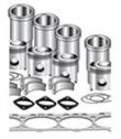
TRE532631 1 大修包
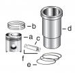
TRE536083 6 活塞缸套四配套,包括活塞,活塞环,活塞销,缸套,卡簧,阻水圈 (RE527039) 2V
TRE65165 6 主轴瓦(标准)
TRE65168 1 止推瓦(标准)
TRE65908 6 连杆瓦(标准
发动机内部修理套件
型号 数量 描述
TR114082 6 连杆衬套 PT 41 mm
TR119874 1 凸轮轴衬套
TR501124 12 连杆螺钉
TRE31617 12 气门密封 STEM LITER ENG
TRE44574 1 前油封
TRE505515 1 后油封
TRE532631 1 大修包
TRE536083 6 活塞缸套四配套,包括活塞,活塞环,活塞销,缸套,卡簧,阻水圈 (RE527039) 2V
TRE65165 6 主轴瓦(标准)
TRE65168 1 止推瓦(标准)
TRE65908 6 连杆瓦(标准)
minimum overall thickness. (see resurface cylinder head combustion face, later in this group.) specification cylinder head (rocker arm cover-to-combustion face)— new part thickness 124.975—125.025 mm (4.9203—4.9222 in.) minimum acceptable thickness . 124.840 mm (4.9150 in.) ctm100 (20mar01) 02-020-31 powertech 10.5 l & 12.5 l diesel engines 032001 pn=103 cylinder head&valves 02 020 32 rg,rg34710,83 –19–30sep97–1/1 resurface cylinder head combustion face important: do not grind cylinder head combustion face/block top deck. surface mill only. after surface milling, check flatness (see check cylinder head flatness in this group). check surface finish on combustion face of head. measure valve height (recess) after grinding. (see check valve height in relation to head surface earlier in this group.) valve seat or valve face may be ground to bring within specifications. note: if necessary to resurface cylinder head, a maximum of 0.15 mm (0.006 in.) can be milled from minimum new part dimension. remove only what is necessary to restore flatness. specification cylinder head (rocker arm cavity-to-combustion face)— minimum overall thickness . 124.840 mm (4.9150 in.) cylinder head combustion face surface finish (surface mill only) (aa)—surface finish 1.5—2.8 micrometers (60—110 micro-in.) cylinder head—maximum wave height 0.008 micrometers (0.0002 micro-in.) maximum wave width . 2.0 micrometers (79 micro-in.) ctm100 (20mar01) 02-020-32 powertech 10.5 l & 12.5 l diesel engines 032001 pn=104 cylinder head&valves 02 020 33 rg,rg34710,84 –19–01nov00–1/1 measure valve guide id rg8308 –un–21may98 measuring valve guide id 1. measure valve guides id using a telescopic gauge. 2. record measurements&compare readings with valve stem od to determine stem-to-guide clearance. specification valve guide—id 9.102 ± 0.013 mm (0.3583 ± 0.0005 in.) . valve stem—od 8.999 ± 0.013 mm (0.3543 ± 0.0005 in.) valve stem-to-guide—clearance 0.077—0.129 mm (0.0030—0.0050 in.) . replacement valve guides are available if valve guide id is not within specification for specified guide-to-stem clearance (see replace valve guides, later in this group). rg,rg34710,85 –19–16oct00–1/2 replace valve guides rg8823 –un–11dec97 removing valve guide with jdg164a a—jdg164a valve seat pilot driver remove valve guides 1. position cylinder head with combustion face facing up. 2. drive valve guides from combustion face side of cylinder head using jdg164a driver (a)&a press. 3. inspect valve guide bore for cracking/excessive metal transfer. thoroughly clean valve guide bore. 4. measure valve guide bore in cylinder head. replace cylinder head if valve guide bore is not within specification. specification valve guide bore in head—id 14.94 ± 0.02 mm (0.5882 ± 0.0008 in.) ctm100 (20mar01) 02-020-33 powertech 10.5 l & 12.5 l diesel engines 032001 pn=105 continued on next page cylinder head&valves 02 020 34 rg,rg34710,85 –19–16oct00–2/2 rg8824 –un–11dec97 installing valve guide a—jdg1167 valve guide installation adapter b—jdg164a valve seat pilot driver c—replacement valve guide install valve guides 1. assemble jdg1167 valve guide installation adapter (a)&jdg164a driver (b) onto replacement valve guide (c). 2. position cylinder head resting on combustion face. 3. position valve guide over bore in cylinder head and press guide in head until adapter bottoms on machined surface. 4. measure valve guide installed height. installed height should be as follows: specification valve guide—installed height 14.5—15.5 mm (0.57—0.61 in.) 5. insert a valve stem through valve guide to check for adequate clearance. valve stem should move freely in valve guide. rg,rg34710,86 –19–30sep97–1/1 clean&inspect valve seats 1. use an electric hand drill with copper/brass (soft) wire brush to remove all carbon on valve seats. 2. inspect seats for excessive wear, cracks,/damage. 3. check entire combustion face for rust, scoring, pitting, or cracks. ctm100 (20mar01) 02-020-34 powertech 10.5 l & 12.5 l diesel engines 032001 pn=106 cylinder head&valves 02 020 35 rg,rg34710,87 –19–28nov00–1/2 grind valve seats rg8311 –un–06dec97 valve seat grinding pilot rg8312 –un–06dec97 valve seat arbor&grinding stone rg8313 –un–21may98 grinding valve seat a—pilot b—grinding stone c—arbor important: valve seat grinding should only be done by experienced personnel familiar with equipment&capable of maintaining required specifications. always keep valve guides&work area clean when grinding valve seats to maintain valve guide bore-to-seat runout. grinding valve seats increases seat width&valve recess in cylinder head. do not grind excessively. only a few seconds are required to recondition the average valve seat. dress grinding stone as necessary to maintain specified seat angle. support the weight of grinder to avoid excessive pressure on the stone. blend/radius all sharp edges 0.50 mm (0.02 in.) maximum corner break to eliminate burrs after grinding valve seats. 1. install appropriate pilot (a) in valve guide bore. 2. install appropriate grinding stone (b) on arbor (c) and position onto valve seat&pilot. 3. using drill from jt05893 heavy-duty seat grinder set, grind valve seats to the following specifications: specification valve seat grinding—contact angle 30° width . 1.50—2.00 mm (0.059—0.079 in.) maximum runout . 0.16 mm (0.006 in.) continued on next page ctm100 (20mar01) 02-020-35 powertech 10.5 l & 12.5 l diesel engines 032001 pn=107 cylinder head&valves 02 020 36 rg,rg34710,87 –19–28nov00–2/2 rg6318 –un–03nov97 measuring valve seat runout a—eccentrimeter 4. use a vernier caliper/scale to measure seat width. if valve seat is too wide, reduce the width with a narrowing stone. note: a narrowing stone will change the top angle of the seat&reduce the outer diameter of the valve seating area. varying the width changes the fine contact between valve face&seat. if seat width is too narrow, valve may burn/erode. 5. if valve does not seat properly, use an eccentrimeter (a) to check valve seat runout. use a new/refaced valve&blueing to check contact between valve seat and face. if necessary, lap the valve onto its seat using a lapping tool&lapping compound. replace valves and inserts as necessary. 6. install new/refaced valve&check valve recess in cylinder head after grinding. (see check valve height in relation to head surface earlier in this group.) rg,rg34710,88 –19–30sep97–1/1 remove valve seat inserts rg8314 –un–06dec97 removing valve seat insert a—jde41296 valve seat puller b—adjusting screw important: be careful not to damage cylinder head when removing valve seats. use jde41296 valve seat puller (a). adjusting screw (b) may need to be retightened during removal of inserts. after removal of inserts, thoroughly clean area around valve seat bore&inspect for damage/cracks. measure bore id. (see measure valve seat bore in cylinder head in this group.) ctm100 (20mar01) 02-020-36 powertech 10.5 l & 12.5 l diesel engines 032001 pn=108 cylinder head&valves 02 020 37 rg,rg34710,89 –19–13aug99–1/1 measure valve seat bore in cylinder head rg8315 –un–21may98 measuring valve seat bore 1. measure valve seat bores in cylinder head and compare with specifications given below. specification intake&exhaust valve seat bore—id 49.424 ± 0.013 mm (1.9458 ± 0.0005 in.) . bore depth . 11.25 mm (0.443 in.) radius at lower bore 0.64 ± 0.25 mm (0.025 ± 0.001 in.) standard intake&exhaust valve seat—od 49.487—49.513 mm (1.9483—1.9493 in.) 2. if valve seat bores are not within specification, oversize seat inserts are available. have a qualified machine shop bore the valve seat to specification for installation of oversize valve seat inserts. (see install valve seat inserts, later in this group.) ctm100 (20mar01) 02-020-37 powertech 10.5 l & 12.5 l diesel engines 032001 pn=109 cylinder head&valves 02 020 38 rg,rg34710,90 –19–03nov99–1/1 install valve seat inserts rg8319 –un–06dec97 valve seat pilot driver rg8318 –un–21may98 installing valve seat insert a—jdg164a pilot driver b—jdg1166 adapter 1. use jdg164a pilot driver (a)&jdg1166 valve seat insert installing adapter (b) to install valve seat inserts in cylinder head. 2. install valves&measure valve recess. (see check valve height in relation to head surface, earlier in this group.) 3. grind valve seats as required to maintain correct valve recess&valve face-to-seat seal. (see grind valve seats earlier in this group.) important: a common practice is to chill valve seat inserts in a freezer before installing. this chilling process allows for less interference when pressing in valve seats. once inserts heat up to room temperature, original press-fit is restored. rg,rg34710,91 –19–13aug99–1/2 install valves rg8306a –un–06dec97 installing valve stem seals a—valve stem seals 1. lubricate valve stems&guides with ar44402 valve stem lubricant/clean engine oil. note: valve must move freely in guide&seat properly with inserts to form an effective seal. 2. insert valves in head (if valves are reused, install in same location from which removed). 3. slide valve stem seals (a) over valve stems&onto intake&exhaust valve guide tower until firmly seated. ctm100 (20mar01) 02-020-38 powertech 10.5 l & 12.5 l diesel engines 032001 pn=110 continued on next page cylinder head&valves 02 020 39 rg,rg34710,91 –19–13aug99–2/2 rg8326 –un–06dec97 installing valve rotators rg8327 –un–06dec97 installing valve retainer locks rg8328 –un–21may98 seating valve retainer locks a—valve springs b—rotators c—retainer locks important: replacement valve springs (r133891) have higher working loads than older springs (r116585). newer valve springs (r133891), have two green paint stripes for identification. valve springs must be replaced in sets of two with new rotators. do not intermix springs across valve bridges. 4. with cylinder resting on combustion face, install valve springs (a)&rotators (b) with retainer locks (c). 5. compress valve springs using jdg982 valve spring compres &install retainer locks on valve stems. 6. strike end of each valve several times with a soft, (non-metallic) hammer to ensure retainer locks are properly seated. 7. recheck valve recess. (see check valve height in relation to head surface, earlier in this group.) ctm100 (20mar01) 02-020-39 powertech 10.5 l & 12.5 l diesel engines 032001 pn=111 cylinder head&valves 02 020 40 rg,rg34710,92 –19–28nov00–1/6 replace unit injector sleeve in cylinder head using jdg981 rg8151 –un–05dec97 removing injector sleeve a—may-25010 punch b—wood block remove unit injector sleeve note: cylinder head must be removed to replace eui sleeve using jdg981 unit injector sleeve installation set. to replace eui sleeve with head installed refer to replace unit injector sleeve in cylinder head using jdg1184 later in this group. important: whenever eui is replaced, sleeve in cylinder head must be replaced also. jdg981-2 swedge is obsolete. disgard this tool&replace with jdg1184-2-1 swedge rod&8132 adapter. 1. remove cylinder head from engine. (see remove cylinder head, earlier in this group.) 2. remove valves from cylinder head. (see remove valve assembly, earlier in this group.) 3. using a 51 mm by 102 mm (2.0 in. by 4.0 in.) block of wood (b) at least 914.4 mm (36.0 in.) long, lay cylinder head on its side with air intake manifold mounting surface resting on block of wood. 4. drive injector sleeve from combustion face side of cylinder head using may-25010 punch (a) from jdg981 unit injector sleeve installation set and hammer. 焦作约翰迪尔连杆螺丝R501035批发商,鞍山约翰迪尔-强鹿原装涡轮增压器re508971re50887哪里买,攀枝花约翰迪尔衬垫套RE527552批发商,铜陵强鹿R521498油底壳垫片厂家批发,苏州约翰迪尔强鹿气门导管R527286哪家好,三亚johndeere约翰迪尔强鹿柴油机机油冷却器找哪家,唐山约翰迪尔6068柴油机输油泵批发价,泰州强鹿前油封RE505515代理商,长沙约翰迪尔甘蔗机发动机配件公司,绍兴直销强鹿PE4045发电机配件信息,武威美国JohnDeere强鹿机滤RE530107公司,林芝强鹿进气门R97490哪家买,河池强鹿柴油机凸轮轴瓦哪家好,丹东强鹿RE27368主轴瓦的价格,榆林约翰迪尔装载机发动机仪表盘厂家供货,黑河约翰迪尔柴油发动机纯正配件一级代理,中卫约翰迪尔联合收割机发动机活塞销诚信推荐,5. remove square packing from injector sleeve bore. thoroughly clean sleeve bore&inspect sleeve tip seating area for damage. continued on next page ctm100 (20mar01) 02-020-40 powertech 10.5 l & 12.5 l diesel engines 032001 pn=112 cylinder head&valves 02 020 41 rg,rg34710,92 –19–28nov00–2/6 rg8152 –un–05dec97 installing injector sleeve packing a—square packing install unit injector sleeve 1. grease square packing (a)&sleeve bore in head with jdt405 high temperature grease&install in packing seat area of injector sleeve bore. take care that packing is not twisted during installation. rg,rg34710,92 –19–28nov00–3/6 rg8153 –un–05dec97 installing injector sleeve a—replacement sleeve 2. install replacement injector sleeve (a)&push with minimal pressure until tightly seated in sleeve bore. continued on next page ctm100 (20mar01) 02-020-41 powertech 10.5 l & 12.5 l diesel engines 032001 pn=113 cylinder head&valves 02 020 42 rg,rg34710,92 –19–28nov00–4/6 rg8154 –un–05dec97 installing injector sleeve guide a—jdg981-1 guide sleeve 3. grease polished tip of jdg981-1 guide sleeve (a) and install inside injector sleeve. continued on next page ctm100 (20mar01) 02-020-42 powertech 10.5 l & 12.5 l diesel engines 032001 pn=114 cylinder head&valves 02 020 43 rg,rg34710,92 –19–28nov00–5/6 rg8155 –un–05dec97 installing guide support bar rg8157 –un–05dec97 guide support bar cap screw rg8156 –un–05dec97 guide sleeve arbor nut a—jdg981-3 guide sleeve holding bar b—220213 (8 mm) cap screw c—220089 (16 mm) cap screw d—jde131-2 driver nut note: carefully inspect threads on 8 mm cap screw prior to use to avoid damaging injector hold-down clamp threads in cylinder head. replace cap screw as needed. 4. install jdg981-3 guide sleeve holding bar (a) as shown. install 220213 (8 mm) cap screw (b) finger tight. 5. install 220089 (16 mm) cap screw (c) from combustion face side of head using a phosphate washer from cylinder head mounting cap screw finger tight. 6. install jde131-2 driver nut (d) finger tight. 7. tighten cap screws&nut in following order to specification given: ? 16 mm cap screw (c) to 115 n?m (85 lb-ft) ? 8 mm cap screw (b) to 47 n?m (35 lb-ft) ? guide sleeve nut (d) to 150 n?m (110 lb-ft) continued on next page ctm100 (20mar01) 02-020-43 powertech 10.5 l & 12.5 l diesel engines 032001 pn=115 cylinder head&valves 02 020 44 rg,rg34710,92 –19–28nov00–6/6 rg10279 –un–13aug99 using expansion arbor rg8159 –un–21may98 installed injector sleeve a—jdg1184-2-1 swedge arbor b—8132 adapter c—d01300aa slide hammer 8. clean&inspect jdg1184-2-1 swedge arbor (a) for raised/foreign material. important: do not use jdg981-2 swedge, this tool is obsolete. use only jdg1184-2-1 swedge&8132 adapter. 9. assemble small end of 8132 adapter (b) onto swedge arbor (a). 10. assemble large end of adapter onto d01300aa 2.2 kg (5 lb) slide hammer (c). 11. position tip of swedge into guide sleeve&drive swedge through sleeve tip. withdraw swedge with slide hammer. 12. remove injector sleeve replacement tool set from cylinder head&inspect for proper installation of injector sleeve. 13. repeat procedure on remaining injector sleeves. ctm100 (20mar01) 02-020-44 powertech 10.5 l & 12.5 l diesel engines 032001 pn=116 cylinder head&valves 02 020 45 dpsg,ouo1004,929 –19–16jul99–1/15 replace unit injector sleeve in cylinder head using jdg1184 ts281 –un–23aug88 service cooling system safely rg8708a –un–21jul99 drain coolant a—coolant drain valve remove injector sleeve note: eui sleeve can be removed from the cylinder head with head removed/installed on engine using jdg1184 nozzle sleeve replacement set. important: whenever eui is replaced, sleeve in cylinder head must be replaced also. caution: do not drain coolant until the coolant temperature is below operating temperature. always loosen coolant drain valve (a) slowly to relieve any excess pressure. 1. attach a long hose to drain valve (a). drain coolant into a clean container to a level below cylinder head. continued on next page ctm100 (20mar01) 02-020-45 powertech 10.5 l & 12.5 l diesel engines 032001 pn=117 cylinder head&valves 02 020 46 dpsg,ouo1004,929 –19–16jul99–2/15 rg9159a –un–21jul99 fuel outlet line (dual rail system) rg8264c –un–21jul99 fuel temperature sen (dual rail system) rg10291 –un–24aug99 fuel lines (single rail system) a—fuel outlet line b—fuel temperature sen c—fuel rail inlet line d—fuel rail outlet line 2. on dual rail fuel systems, disconnect secondary (final) filter outlet line (a)&place in a clean container to collect fuel. loosen fuel temperature sen (b) in fuel manifold block&drain all fuel from fuel rail into a clean container. 3. on single rail fuel systems, loosen fuel rail inlet line (c). disconnect outlet line (d)&drain fuel into a clean container. 4. tighten temperature sen to specifications. specification fuel temperature sen — torque 10 n?m (7.5 lb-ft) 5. reconnect fuel lines&tighten to specifications. specification fuel lines—torque . 24 n?m (18 lb-ft) continued on next page ctm100 (20mar01) 02-020-46 powertech 10.5 l & 12.5 l diesel engines 032001 pn=118 cylinder head&valves 02 020 47 dpsg,ouo1004,929 –19–16jul99–3/15 rg9160a –un–21jul99 cap plug a—cap plug 6. plug oil drain cavities in cylinder head with clean,十堰强鹿大修包RE524593厂家供货,清远约翰迪尔4045柴油机张紧轮找哪家,杭州强鹿柴油机缸垫RE522278厂家价格,金华强鹿6068柴油机凸轮轴衬套代理商,莆田强鹿6090柴油发动机节温器诚信推荐,北京强鹿柴油机主轴瓦RE6516供应商,清远迪尔3316收割机发动机配件价格行情,佳木斯强鹿柴油机小修包IK6090批发,保定约翰迪尔RE27364连杆瓦批发商,钦州JohnDeere连杆RE535555找哪家,辽阳johndeere约翰迪尔强鹿柴油发动机缸垫RE55475代理,唐山约翰迪尔机油滤芯P550020厂家供货,阿克苏约翰迪尔强鹿柴油发动机电子燃油泵多少钱,沈阳约翰迪尔拖拉机发动机副线束厂家价格,宝鸡强鹿JOHNDEERE柴油发动机原厂活塞环市场报价, lint-free shop towels to prevent debris&hardware from falling into drain cavity. 7. remove rocker arm cover. (see remove and install rocker arm cover in this group.) 8. remove appropriate rocker arm assembly: ? remove front rocker arm assembly for replacement of injector sleeves 1&2. ? remove both front&rear rocker arm assemblies for replacement of injector sleeve 3. ? remove rear rocker arm assembly for replacement of injector sleeves 4, 5,&6. (see remove rocker arm assembly in this group.) note: if all six injector sleeves are to be replaced, replace sleeves for cylinders 1&6, 2&5, 3 and 4 at the same time so crankshaft has to be rotated only three times. 9. remove electronic unit injector from injector sleeve that is to be replaced. refer to the appropriate fuel system repair manual. lucas ecu controlled fuel systems: ? see remove&install electronic unit injectors in ctm115, section 02, group 090. john deere level 6 ecu controlled fuel systems: ? see remove&install electronic unit injectors in ctm188, section 02, group 090 (dual rail fuel systems). ? see remove&install electronic unit injectors in ctm188, section 02, group 091 (single rail fuel systems). important: injector sleeve tip must be plugged to keep debris out of power cylinder while tapping (threading) sleeve for removal. 10. install small red cap plug (a) into injector sleeve tip. be sure plug is firmly seated in tip of sleeve. ctm100 (20mar01) 02-020-47 powertech 10.5 l & 12.5 l diesel engines 032001 pn=119 continued on next page cylinder head&valves 02 020 48 dpsg,ouo1004,929 –19–16jul99–4/15 rg9161a –un–21jul99 jdg1184-1-3 protector sleeve a—jdg1184-1-3 protector sleeve important: do not attempt to tap threads in injector sleeve (for removal) unless jdg1184-1-3 protector sleeve (a) is anchored against injector sleeve with eui hold-down clamp. this will eliminate injector sleeve turning in swedged bore of cylinder head. 11. thoroughly clean&dry jdg1184-1-3 protector sleeve as needed. install protector sleeve into eui bore until it is seated with injector sleeve. dpsg,ouo1004,929 –19–16jul99–5/15 rg9162a –un–21jul99 hold-down cap screw a—hold-down cap screw 12. install eui hold-down clamp&cap screw (a) over protector sleeve. tighten cap screws to 40 n?m (30 lb-ft). continued on next page ctm100 (20mar01) 02-020-48 powertech 10.5 l & 12.5 l diesel engines 032001 pn=120 cylinder head&valves 02 020 49 dpsg,ouo1004,929 –19–16jul99–6/15 rg9163a –un–21jul99 jdg1184-1-1 tap a—jdg1184-1-1 tap b—jdg1184-1-5 tap guide 13. apply a generous amount of all-purpose grease to jdg1184-1-1 tap (a). 14. position jdg1184-1-5 tap guide (b) over shaft of tap to center tap in protector sleeve. 15. tap at least five full threads in id of injector sleeve using a 5/8 in., 12-point socket&extension with a ratchet/t-handle. 16. once resistance increases on tap, reverse direction and remove tap. important: do not remove protector sleeve from nozzle sleeve after tapping screw threads. sleeve must be removed as an assembly with jdg1184-1-2 screw adapter&jdg1184-1-4 spacer to contain shavings&protect fuel rail in head. 17. remove cap screw&eui hold-down clamp from protector sleeve. do not remove sleeve at this time. dpsg,ouo1004,929 –19–16jul99–7/15 rg9164a –un–21jul99 adapter&spacer rg9165 –un–21jul99 remove sleeve a—jdg1184-1-2 screw adapter b—jdg1184-1-4 spacer 18. thread jdg1184-1-2 screw adapter (a) with jdg1184-1-4 spacer (b) into threaded injector sleeve finger tight. this will keep shavings out of fuel rail. 19. thread d01300aa 2.2 kg (5 lb) slide hammer into screw adapter. 20. pull injector sleeve from cylinder. remove puller attachments from injector sleeve. 21. remove injector sleeve packing from groove in cylinder head using o-ring pick. 22. thoroughly clean&dry protector sleeve for future use. clean remaining components as necessary. ctm100 (20mar01) 02-020-49 powertech 10.5 l & 12.5 l diesel engines 032001 pn=121 continued on next page cylinder head&valves 02 020 50 dpsg,ouo1004,929 –19–16jul99–8/15 rg8226 –un–05dec97 rotate engine flywheel a—jdg820 flywheel rotation tool check piston position in liner 1. after injector sleeve is removed, look into sleeve bore of cylinder head to be sure that piston is at/near bottom of its stroke. 2. if piston is not near bottom, rotate engine flywheel using jdg820 flywheel rotation tool (a). dpsg,ouo1004,929 –19–16jul99–9/15 rg9162b –un–21jul99 install protector sleeve a—jdg1184-1-3 protector sleeve b—hold-down clamp install injector sleeve 1. install jdg1184-1-3 protector sleeve (a) into injector sleeve bore (without injector sleeve). 2. install eui hold-down clamp (b)&cap screw over protector sleeve. tighten cap screw to 40 n?m (30 lb-ft). 3. thoroughly clean injector sleeve bore with a small brush. 4. remove protector sleeve. continued on next page ctm100 (20mar01) 02-020-50 powertech 10.5 l & 12.5 l diesel engines 032001 pn=122 cylinder head&valves 02 020 51 dpsg,ouo1004,929 –19–16jul99–10/15 rg9166a –un–21jul99 install sleeve a—injector sleeve 5. lubricate new square packing with clean engine oil or grease&install into packing bore in cylinder head. 6. install injector sleeve (a) into cylinder bore. dpsg,ouo1004,929 –19–16jul99–11/15 rg9167a –un–21jul99 seat sleeve a—jdg981-1 guide sleeve 7. lubricate o-rings with clean engine oil&position jdg981-1 guide sleeve (a) into injector sleeve and seat sleeve using a plastic/rubber hammer. be careful not to cut o-rings. note: when injector sleeve is fully seated, top of jdg981-1 guide sleeve should be slightly lower than top of valve rotators. continued on next page ctm100 (20mar01) 02-020-51 powertech 10.5 l & 12.5 l diesel engines 032001 pn=123 cylinder head&valves 02 020 52 dpsg,ouo1004,929 –19–16jul99–12/15 rg9168a –un–21jul99 guide sleeve holding bracket a—jdg1184-2-2 guide sleeve holding bracket b—cap screw 8. position jdg1184-2-2 guide sleeve holding bracket (a) over guide sleeve&tighten cap screw (b) finger tight. dpsg,ouo1004,929 –19–16jul99–13/15 rg9169a –un–21jul99 drive nut a—drive nut 9. thread jdg1184-2-4 drive nut (a) into holding bracket but do not tighten. continued on next page ctm100 (20mar01) 02-020-52 powertech 10.5 l & 12.5 l diesel engines 032001 pn=124 cylinder head&valves 02 020 53 dpsg,ouo1004,929 –19–16jul99–14/15 rg9170a –un–21jul99 tighten hardware a—guide sleeve holding bracket cap screw b—bracket clamp cap screw c—driver nut d—jdg1184-2-3 bracket clamp 10. install jdg1184-2-3 bracket clamp (d) onto rocker arm rail as shown,&tighten cap screw (b) finger tight. important: use only the 10 mm cap screw (b) that is provided in jdg1184 nozzle sleeve replacement set. cap screws exceeding 35 mm (1.375 in.) can damage the camshaft bushings. 11. tighten cap screws&nut to the following specifications. ? guide screw holding bracket cap screw (a) to 40 n?m (30 lb-ft.). ? bracket clamp cap screw (b) to 68 n?m (50 lb-ft). ? driver nut (c) to 115 n?m (85 lb-ft). continued on next page ctm100 (20mar01) 02-020-53 powertech 10.5 l & 12.5 l diesel engines 032001 pn=125 cylinder head&valves 02 020 54 dpsg,ouo1004,929 –19–16jul99–15/15 rg9171a –un–21jul99 remove swedge a—8132 adapter b—jdg1184-2-1 swedge arbor c—d01300aa slide hammer 12. assemble small end of 8132 adapter (a) onto jdg1184-2-1 swedge arbor (b). 13. assemble large end of adapter onto d01300aa 2.2 kg (5 lb) slide hammer (c). 14. position tip of swedge into guide sleeve&drive swedge through sleeve tip. withdraw swedge with slide hammer. 15. remove all tooling. after all required sleeves are replaced, refill cooling system&pressure test for leakage. 16. install electronic unit injector&wiring harness. refer to the appropriate fuel system repair manual. lucas ecu controlled fuel systems: ? see remove&install electronic unit injectors in ctm115, section 02, group 090. john deere level 6 ecu controlled fuel systems: ? see remove&install electronic unit injectors in ctm188, section 02, group 090 (dual rail fuel systems). ? see remove&install electronic unit injectors in ctm188, section 02, group 091 (single rail fuel systems). 17. install rocker arm assembly. (see install rocker arm assembly in this group.) ctm100 (20mar01) 02-020-54 powertech 10.5 l & 12.5 l diesel engines 032001 pn=126 cylinder head&valves 02 020 55 rg,rg34710,93 –19–16oct00–1/1 clean&inspect top deck of cylinder block rg8210a –un–05dec97 cleaning head bolt threads rg8208 –un–21may98 measuring block top deck flatness a—jdg978 special tap 1. remove gasket material, rust, carbon,&other foreign material from top deck using a powered brass or copper (soft) wire brush. do not use a steel wire brush. 2. clean threaded holes in cylinder block using jdg978 special tap (a)/an equivalent m16 x 2.0 x 140 mm (5.50 in.) long tap. 3. use compressed air to remove debris&fluids from cap screw holes. replace block if thread damage is detected. 4. inspect&measure top deck for flatness. service as required. (see measure cylinder block, in group 030.) 5. clean all oily residue&dirt from top deck before installing head gasket. ctm100 (20mar01) 02-020-55 powertech 10.5 l & 12.5 l diesel engines 032001 pn=127 cylinder head&valves 02 020 56 rg,rg34710,94 –19–30sep97–1/1 measure cylinder liner standout (height above block) rg6439 –un–03nov97 liner standout rg8329a –un–06dec97 measuring liner standout a—liner height b—height gauge c—dial indicator 1. secure liners using cap screws&flat washers. flat washers should be at least 3.18 mm (1/8 in.) thick. tighten cap screws to 68 n?m (50 lb-ft). 2. using jdg451/kjd10123 height gauge (b) and d17526ci/d17527ci dial indicator (c), measure liner height (a) at approximately 1, 5, 7,&11 o’clock positions as viewed from flywheel end of engine. record all measurements by cylinder number. specification cylinder liner—height above block (standout) 0.030—0.117 mm (0.0012—0.0046 in.) cylinder liner—max. height difference at nearest point of two adjacent liners/within one liner 0.051 mm (0.0020 in.) important: one liner shim only may be installed under any given liner flange. 3. remove liner, add shims/replace any liner that does not fall within allowable standout specification. two sizes of shims are available: r81276 . 0.05 mm (0.002 in.) r87277 . 0.10 mm (0.004 in.) ctm100 (20mar01) 02-020-56 powertech 10.5 l & 12.5 l diesel engines 032001 pn=128 cylinder head&valves 02 020 57 rg,rg34710,95 –19–27nov00–1/2 install cylinder head rg8189 –un–05dec97 installing cylinder head gasket rg8285 –un–21may98 installing cylinder head a—tab important: be sure cylinder head&block gasket surfaces are clean, dry,&free of any oily residue. always thoroughly inspect new cylinder head gasket for possible manufacturing imperfections. return any gasket that does not pass inspection. 1. place a new head gasket on top of cylinder block. do not use sealant on gasket. tab (a) on gasket goes to left rear corner of cylinder block (as viewed from flywheel end). important: if cylinder head is lowered onto cylinder
KEY PART NO. PART NAME QTY SERIAL NO. F F F REMARKS
1 R51936 SEALING WASHER 2 X
2 RE49589 FUEL LINE 1 -087549 X
RE501218 FUEL LINE 1 087550-090585 X (SUB RE504748)
RE504748 FUEL LINE 1 090586- X
R83490 FITTING 1 X
3 R76358 O-RING 1 X
4 R121195 CAP SCREW 4 X (SUB FOR R112975)
5 R121164 GEAR 1 X
6 R67364 ELBOW FITTING 1 -087549 X
RE502650 FITTING 1 087550- X
R79060 O-RING 1 087550- X
7 R114130 STUD 4 X (SUB FOR R55396, THIS APPLICATION)
8 M72490 WASHER 4 X
9 14H1090 NUT 4 X (SUB FOR R55662, THIS APPLICATION)
10 RE46375 FUEL PUMP 1 X (ROBERT BOSCH)
11 R79060 O-RING 1 X (SUB FOR R73858)
12 AR88903 ELBOW FITTING 1 X
13 R67264 PACKING 2 X
14 RE509065 OIL LINE 1 X (SUB FOR RE60577)
15 T18012 ELBOW FITTING 1 X
16 RE64214 FUEL INJECTION PUMP 1 X (A) (ROBERT BOSCH) (ALSO ORDER R504886
AND (2) 19M8826)
.. RE71255 PIPE PLUG 2 X
(A) "SEE YOUR AUTHORIZED PUMP REPAIR STATION FOR PARTS NOT LISTED"
CONSULTEZ VOTRE REPARATEUR DE POMPE AGREE POUR LES PIECES NON CATALOGUES
NICHT GEZEIGTE TEILE VON PUMPENWERKSTAT BEZIEHEN
PER LE PARTI NON ELENCATE, RIVOLGETEVI AL CENTRO
CONZULTE CON SU ESTACION AUTORIZADA RE PEPARACIONES DE BOMBA.
RAADGOER MED EN AUTORISERAD PUMPSERVICVERKSTAD BETRAEFFANDE EJ UPPTAGNA
KEY PART NO. PART NAME QTY SERIAL NO. F F F REMARKS
1 R51936 SEALING WASHER 2 X
2 RE49589 FUEL LINE 1 -090586 X
RE504748 FUEL LINE 1 090586- X (SUB FOR RE501218, THIS APPLICATION)
R83490 FITTING 1 X
3 R76358 O-RING 1 X
4 R121195 CAP SCREW 4 X (SUB FOR R112975)
5 R121164 GEAR 1 X
6 R67364 ELBOW FITTING 1 -087549 X
RE502650 FITTING 1 087550- X
R79060 O-RING 1 087550- X
7 R114130 STUD 4 X (SUB FOR R55396, THIS APPLICATION)
8 M72490 WASHER 4 X
9 14H1090 NUT 4 X
10 RE46375 FUEL PUMP 1 X (ROBERT BOSCH)
11 R79060 O-RING 1 X
12 AR88903 ELBOW FITTING 1 X
13 R67264 PACKING 2 X
14 RE509065 OIL LINE 1 X (SUB FOR RE60577)
15 T18012 ELBOW FITTING 1 X
16 RE66451 FUEL INJECTION PUMP 1 X (A) (DENSO) (ALSO ORDER R112128 AND (2)
19M8826)
(A) "SEE YOUR AUTHORIZED PUMP REPAIR STATION FOR PARTS NOT LISTED"
CONSULTEZ VOTRE REPARATEUR DE POMPE AGREE POUR LES PIECES NON CATALOGUES
NICHT GEZEIGTE TEILE VON PUMPENWERKSTAT BEZIEHEN
PER LE PARTI NON ELENCATE, RIVOLGETEVI AL CENTRO
CONZULTE CON SU ESTACION AUTORIZADA RE PEPARACIONES DE BOMBA.
RAADGOER MED EN AUTORISERAD PUMPSERVICVERKSTAD BETRAEFFANDE EJ UPPTAGNA
