珀金斯3012用户维修操作手册供应商,珀金斯3012用户维修操作手册技术价格规格咨询服务,珀金斯3012用户维修操作手册零配件供应,珀金斯3012用户维修操作手册售后服务中心,珀金斯3012用户维修操作手册,珀金斯3012用户维修操作手册详细的技术参数,

珀金斯3012用户维修操作手册
详细描述
|
Perkins 3000 Series |
|
USER’S HANDBOOK |
|
3012/CV12 12 cylinder diesel engines for industrial applications |
|
The contents of this handbook are applicable to both CV12 and 3000 Series - 3012 engines. |
|
Publication TSD 3138 (issue 13) |
|
©Proprietary information of Perkins Group Limited, all rights reserved The information is correct at the time of print. Published in May 2001 by Technical Publications, Perkins Engines Company Limited, Lancaster Road, Shrewsbury, Shropshire SY1 3NX, England |
|
1 |
|
This document has been printed from SPI². Not for Resale |
![]()
![]()

|
2 |
|
This document has been printed from SPI². Not for Resale |
![]()
![]()
![]()

|
Contents |
|
1 General information |
|
Introduction . . . . . . . . . . . . . . . . . . . . . . . . . . . . . . . . . . . . . . . . . . . . . . . . . . . . . . . . . . . . 5 How to care for your engine . . . . . . . . . . . . . . . . . . . . . . . . . . . . . . . . . . . . . . . . . . . . . . . 5 Engine identification . . . . . . . . . . . . . . . . . . . . . . . . . . . . . . . . . . . . . . . . . . . . . . . . . . . . . 6 Perkins companies . . . . . . . . . . . . . . . . . . . . . . . . . . . . . . . . . . . . . . . . . . . . . . . . . . . . . . 7 Safety precautions . . . . . . . . . . . . . . . . . . . . . . . . . . . . . . . . . . . . . . . . . . . . . . . . . . . . . . 8 |
|
2 Engine views |
|
Introduction . . . . . . . . . . . . . . . . . . . . . . . . . . . . . . . . . . . . . . . . . . . . . . . . . . . . . . . . . . . . 9 Location of engine parts . . . . . . . . . . . . . . . . . . . . . . . . . . . . . . . . . . . . . . . . . . . . . . . . . . 9 |
|
3 Operation instructions |
|
Preparations for a new or an overhauled engine . . . . . . . . . . . . . . . . . . . . . . . . . . . . . . 11 How to start a new or overhauled engine or an engine which has been in storage . . . . 12 Normal start procedures . . . . . . . . . . . . . . . . . . . . . . . . . . . . . . . . . . . . . . . . . . . . . . . . . 13 How to start the engine in low ambient temperatures . . . . . . . . . . . . . . . . . . . . . . . . . . . 13 Precautions . . . . . . . . . . . . . . . . . . . . . . . . . . . . . . . . . . . . . . . . . . . . . . . . . . . . . . . . . . . 13 How to stop the engine . . . . . . . . . . . . . . . . . . . . . . . . . . . . . . . . . . . . . . . . . . . . . . . . . . 13 |
|
4 Preventive maintenance |
|
Preventive maintenance periods . . . . . . . . . . . . . . . . . . . . . . . . . . . . . . . . . . . . . . . . . . . 15 Schedule for engines in normal use . . . . . . . . . . . . . . . . . . . . . . . . . . . . . . . . . . . . . . . . 16 Schedule for engines in intermittent use . . . . . . . . . . . . . . . . . . . . . . . . . . . . . . . . . . . . . 17 Coolant level . . . . . . . . . . . . . . . . . . . . . . . . . . . . . . . . . . . . . . . . . . . . . . . . . . . . . . . . . . 18 Lubricating oil level . . . . . . . . . . . . . . . . . . . . . . . . . . . . . . . . . . . . . . . . . . . . . . . . . . . . . 18 Restriction indicator . . . . . . . . . . . . . . . . . . . . . . . . . . . . . . . . . . . . . . . . . . . . . . . . . . . . 19 How to renew the elements of the air filters . . . . . . . . . . . . . . . . . . . . . . . . . . . . . . . . . . 19 How to drain the primary fuel filter . . . . . . . . . . . . . . . . . . . . . . . . . . . . . . . . . . . . . . . . . 19 How to check the drive belts . . . . . . . . . . . . . . . . . . . . . . . . . . . . . . . . . . . . . . . . . . . . . . 20 How to renew the fan belts . . . . . . . . . . . . . . . . . . . . . . . . . . . . . . . . . . . . . . . . . . . . . . . 20 How to renew the alternator belt . . . . . . . . . . . . . . . . . . . . . . . . . . . . . . . . . . . . . . . . . . . 20 How to check the specific gravity of the coolant . . . . . . . . . . . . . . . . . . . . . . . . . . . . . . . 21 How to check the pH value of the coolant . . . . . . . . . . . . . . . . . . . . . . . . . . . . . . . . . . . . 21 How to renew the engine lubricating oil . . . . . . . . . . . . . . . . . . . . . . . . . . . . . . . . . . . . . 22 How to renew the canisters of the oil filter . . . . . . . . . . . . . . . . . . . . . . . . . . . . . . . . . . . 22 |
|
Continued |
|
3 |
|
This document has been printed from SPI². Not for Resale |
![]()
![]()
|
How to clean the primary fuel filter . . . . . . . . . . . . . . . . . . . . . . . . . . . . . . . . . . . . . . . . . 23 How to renew the canister of the main fuel filter . . . . . . . . . . . . . . . . . . . . . . . . . . . . . . . 23 How to check/adjust the timing of the fuel injection pump . . . . . . . . . . . . . . . . . . . . . . . . 24 Fuel injector fault . . . . . . . . . . . . . . . . . . . . . . . . . . . . . . . . . . . . . . . . . . . . . . . . . . . . . . . 25 How to remove the fuel injectors . . . . . . . . . . . . . . . . . . . . . . . . . . . . . . . . . . . . . . . . . . . 25 How to correct the fuel injector sleeves . . . . . . . . . . . . . . . . . . . . . . . . . . . . . . . . . . . . . . 25 How to fit the fuel injectors . . . . . . . . . . . . . . . . . . . . . . . . . . . . . . . . . . . . . . . . . . . . . . . 25 How to eliminate air from the fuel system . . . . . . . . . . . . . . . . . . . . . . . . . . . . . . . . . . . . 27 How to check the tappet clearances . . . . . . . . . . . . . . . . . . . . . . . . . . . . . . . . . . . . . . . . 28 Turbochargers . . . . . . . . . . . . . . . . . . . . . . . . . . . . . . . . . . . . . . . . . . . . . . . . . . . . . . . . . 29 Alternator . . . . . . . . . . . . . . . . . . . . . . . . . . . . . . . . . . . . . . . . . . . . . . . . . . . . . . . . . . . . . 29 How to drain the coolant system . . . . . . . . . . . . . . . . . . . . . . . . . . . . . . . . . . . . . . . . . . . 29 How to clean the coolant system . . . . . . . . . . . . . . . . . . . . . . . . . . . . . . . . . . . . . . . . . . . 29 How to fill the coolant system . . . . . . . . . . . . . . . . . . . . . . . . . . . . . . . . . . . . . . . . . . . . . 29 |
|
5 Engine fluids |
|
Diesel fuel . . . . . . . . . . . . . . . . . . . . . . . . . . . . . . . . . . . . . . . . . . . . . . . . . . . . . . . . . . . . 31 Coolant . . . . . . . . . . . . . . . . . . . . . . . . . . . . . . . . . . . . . . . . . . . . . . . . . . . . . . . . . . . . . . 31 Lubricating oil . . . . . . . . . . . . . . . . . . . . . . . . . . . . . . . . . . . . . . . . . . . . . . . . . . . . . . . . . 32 Recommended oils for Europe . . . . . . . . . . . . . . . . . . . . . . . . . . . . . . . . . . . . . . . . . . . . 33 Recommended oils for remainder of the world . . . . . . . . . . . . . . . . . . . . . . . . . . . . . . . . 34 Warranty . . . . . . . . . . . . . . . . . . . . . . . . . . . . . . . . . . . . . . . . . . . . . . . . . . . . . . . . . . . . . 34 |
|
6 Fault diagnosis |
|
Problems and possible causes . . . . . . . . . . . . . . . . . . . . . . . . . . . . . . . . . . . . . . . . . . . . 36 Code list of possible causes . . . . . . . . . . . . . . . . . . . . . . . . . . . . . . . . . . . . . . . . . . . . . . 37 |
|
7 Engine preservation |
|
Introduction . . . . . . . . . . . . . . . . . . . . . . . . . . . . . . . . . . . . . . . . . . . . . . . . . . . . . . . . . . . 39 Short period storage . . . . . . . . . . . . . . . . . . . . . . . . . . . . . . . . . . . . . . . . . . . . . . . . . . . . 39 Long period storage . . . . . . . . . . . . . . . . . . . . . . . . . . . . . . . . . . . . . . . . . . . . . . . . . . . . . 39 Removal from storage . . . . . . . . . . . . . . . . . . . . . . . . . . . . . . . . . . . . . . . . . . . . . . . . . . . 40 Approved products for engine preservation . . . . . . . . . . . . . . . . . . . . . . . . . . . . . . . . . . . 41 |
|
8 Parts and Service |
|
Introduction . . . . . . . . . . . . . . . . . . . . . . . . . . . . . . . . . . . . . . . . . . . . . . . . . . . . . . . . . . . 43 Service literature . . . . . . . . . . . . . . . . . . . . . . . . . . . . . . . . . . . . . . . . . . . . . . . . . . . . . . . 43 Training . . . . . . . . . . . . . . . . . . . . . . . . . . . . . . . . . . . . . . . . . . . . . . . . . . . . . . . . . . . . . . 43 Service Bulletins . . . . . . . . . . . . . . . . . . . . . . . . . . . . . . . . . . . . . . . . . . . . . . . . . . . . . . . 43 |
|
9 Engine data |
|
3012 diesel engine . . . . . . . . . . . . . . . . . . . . . . . . . . . . . . . . . . . . . . . . . . . . . . . . . . . . . 45 |
|
4 |
|
This document has been printed from SPI². Not for Resale |
![]()
![]()
|
1 |
|
General information |
|
1 |
|
Introduction |
|
The 3012 heavy duty diesel engine is the latest development from Perkins Engines Company |
|
How to care for your engine |
|
Limited, a world leader in the design and manufacture of high performance diesel engines. |
|
This handbook has been written to assist you to maintain and operate your engine correctly. |
|
More than fifty years of diesel production experience, together with the use of the latest technology, have been used in the manufacture of your engine to give you reliable and economic power. |
|
To obtain the best performance and the longest life from your engine, you must ensure that the maintenance operations are done at the intervals shown in ‘Preventive maintenance’. If the engine is operated in a very dusty environment or other adverse conditions, certain maintenance intervals will have to be reduced. Renew the filter elements and the lubricating oil regularly to ensure that the inside of your engine remains clean. |
|
To ensure that you use the correct information for your specific engine type, refer to ‘Engine identification’ on page 6. |
|
Danger is indicated in the text by two methods: |
|
Warning! This indicates that there is a possible danger to the person. |
|
Ensure that all adjustments and repairs are done by personnel who have had the correct training. Perkins distributors have this type of personnel available. You can also obtain parts and service from your Perkins distributor. If you do not know the address of your nearest distributor, enquire at one of the Perkins companies listed on page 7. |
|
Caution: This indicates that there is a possible danger to the engine. |
|
Note: Is used where the information is important, but there is not a danger. |
|
The left and right sides of the engine are as seen from the rear (flywheel) end. Where reference is made to ‘A’ and ‘B’ banks of cylinders: ‘A’ bank is to the right and ‘B’ bank is to the left when viewed from the rear end. |
|
Read the ‘Safety precautions’ and remember them. They are given for your protection and must be applied at all times. |
|
5 |
|
This document has been printed from SPI². Not for Resale |
![]()
![]()
|
1 Engine identification |
|
If you need parts, service or information for your engine, you must give the complete engine number to your Perkins distributor. |
|
The engine number is stamped on the data plate which is fastened to the left side of the crankcase. |
|
For early engines, a typical engine number is: 6A27487U 59426U, which consists of these codes: |
|
6A |
|
= |
|
Engine family |
|
27487 = |
|
Engine number |
|
U |
|
= |
|
Country of manufacture Build line number Year of manufacture |
|
59426 = |
|
U |
|
= |
|
Engines made after August 1994, have a new engine number system. For these engines, a typical number is: SGJ 12 0029 U 3254 C, which consists of these codes: |
|
SG J |
|
= = = = = = = |
|
Engine application |
|
Engine type |
|
12 |
|
Number of engine cylinders Engine specification number Country of manufacture Build line number |
|
0029 U |
|
3254 C |
|
Year of manufacture |
|
Units such as the fuel injection pump and turbochargers have their own data plates. |
|
6 |
|
This document has been printed from SPI². Not for Resale |
![]()
![]()
|
1 |
|
Perkins companies |
|
Korea |
|
Perkins Engines (Korea) Textile Center 12F Daechi 3 dong 944-31 Kangnam-Ku |
|
Australia |
|
Perkins Engines Australia Pty. Limited, Suite 4, 13A Main Street, |
|
Mornington, Victoria 3931, Australia. Telephone: 0061 (0)597 51877 Telex: Perkoil AA 30816 |
|
Seoul, 135-283 Korea Telephone: (822) 528 3377 Fax: (822) 528 3378 |
|
Fax: 0061 (0)597 1305 |
|
China |
|
Singapore |
|
Perkins Engines (Tianjin) Limited, Jinwei Road, |
|
Perkins Engines (Asia Pacific) Pte. Limited, 20 Harbour Drive, |
|
Beichen District, Tianjin, 300402 |
|
#07-06A, PSA Vista, Singapore 117612. |
|
China Telephone: (86) (22) 2699 2288 Fax: (86) (22) 2699 3784 |
|
Telephone: (65) 874 7712 Fax: (65) 874 7722 |
|
United Kingdom |
|
France |
|
Perkins Engines Company Limited, Lancaster Road, Shrewsbury, SY1 3NX, England. |
|
Perkins France SAS, "Parc des reflets", |
|
165 Avenue du Bois de la Pie, 95700 Roissy Charles de Gaulle, France. Telephone: 0033 (01) 49-90-7171 Fax: 0033 (01) 49-90-7190 |
|
Telephone: 0044 (0)1743 212000 Telex: 35171 PESL G Fax: 0044 (0)1743 212700 |
|
United States of America |
|
Germany |
|
Perkins Engines - North America 12025, Tech Center Drive Livonia Michigan 48150 USA |
|
Perkins Motoren G.m.b.H., Saalaeckerstrasse 4, 63801 Kleinostheim, Germany. |
|
Telephone: 0049 6027 5010 Fax: 0049 6027 501124 |
|
Telephone: 001 313 266 5427 Fax: 001 313 266 2700 |
|
Italy |
|
Perkins Engines Latin America Inc, Suite 620, |
|
Motori Perkins S.p.A., |
|
Via Socrate 8 |
|
999, Ponce de Leon Boulevard, Coral Gables, Florida 33134, |
|
22070 Casnate con Bernate (Como), Italy. Telephone: 0039 (0)31 564625/564633 Fax: 0039 (0)31 565480/564145/396001 |
|
USA. |
|
Telephone: 001 305 442 7413 Telex: 32501 Perken G Fax: 001 305 442 7419 |
|
Japan |
|
Perkins Engines, Inc. Japan Branch, 8 Fl, 2-2-19 Akasaka, Minato-ku, Tokyo 107-0052, Japan. Telephone: 0081 (0)3 3560 3877 Fax: 0081 (0)3 3560 3878 |
|
In addition to the above companies, there are |
|
Perkins distributors in most countries. Perkins Engines Company Limited, Shrewsbury or one of the above companies can provide details. |
|
7 |
|
This document has been printed from SPI². Not for Resale |
![]()
![]()
|
1 Safety precautions |
|
Disconnect the battery terminals before a repair is made to the electrical system. |
|
These safety precautions are important. |
|
Only one person must control the engine. |
|
Reference must also be made to the local regulations in the country of operation. |
|
Ensure that the engine is operated only from the control panel or from the operator’s position. |
|
If your skin comes into contact with high-pressure fuel, obtain medical assistance immediately. |
|
Only use these engines in the type of application for which they have been designed. |
|
Diesel fuel and lubricating oil (especially used lubricating oil) can damage the skin of certain persons. Protect your hands with gloves or a special solution to protect the skin. |
|
Do not change the specification of the engine. Do not smoke when you put fuel in the tank. |
|
Clea, n away fuel which has been spilt. Material which has been contaminated by fuel must be moved to a safe place. |
|
Do not wear clothing which is contaminated by lubricating oil. Do not put material which is contaminated with oil into the pockets. |
|
Do not put fuel in the tank while the engine runs (unless it is absolutely necessary). |
|
Discard used lubricating oil in a safe place to prevent contamination. |
|
Do not clean, add lubricating oil, or adjust the engine while it runs (unless you have had the correct training; even then extreme caution must be used to prevent injury). |
|
Ensure that the control lever of the transmission drive is in the ‘out-of-drive’ position before the engine is started. |
|
Do not make adjustments that you do not understand. |
|
The combustible material of some components of the engine (for example certain seals) can become extremely dangerous if it is burned. Never allow this burnt material to come into contact with the skin or with the eyes. |
|
Ensure that the engine does not run in a location where it can cause a concentration of toxic emissions. |
|
Other persons must be kept at a safe distance while the engine or equipment is in operation. |
|
Fuel and oil pipes MUST be inspected for cracks or damage before they are fitted to the engine. |
|
Do not permit loose clothing or long hair near moving parts. |
|
Fit only genuine Perkins parts. |
|
Keep away from moving parts during engine operation. Warning! Some moving parts cannot be seen clearly while the engine runs. |
|
Do not operate the engine if a safety guard has been removed. |
|
Do not remove the filler cap of the cooling system while the engine is hot and while the coolant is under pressure, because dangerous hot coolant can be discharged. |
|
Do not use salt water or any other coolant which can cause corrosion in the closed coolant circuit. |
|
Do not allow sparks or fire near the batteries (especially when the batteries are on charge) because the gases from the electrolyte are highly flammable. The battery fluid is dangerous to the skin and especially to the eyes. |
|
8 |
|
This document has been printed from SPI². Not for Resale |
![]()
![]()
![]()
![]()
![]()
![]()
![]()
![]()
![]()
![]()
![]()
![]()
![]()
![]()
![]()
![]()
![]()
![]()
![]()
![]()
![]()
![]()
![]()
![]()
![]()
![]()
![]()
![]()
|
2 |
|
Engine views |
|
2 |
|
Introduction |
|
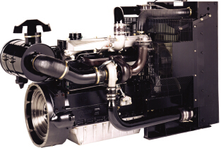
Perkins engines are built for specific applications and the views which follow do not necessarily match your engine specification. |
|
Location of engine parts |
|
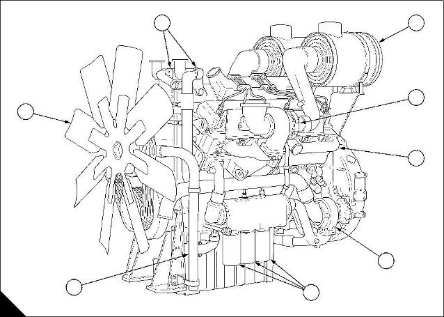
Front and left side view of the 3012 engine |
|
1 ‘B’ bank air cleaner 2 ‘B’ bank turbocharger 3 Exhaust manifold 4 Coolant pump |
|
5 Canisters of the lubricating oil filter 6 Crankcase breather 7 Fan |
|
8 Thermostat housings |
|
8 |
|
1 |
|
2 3 |
|
7 |
|
4 |
|
6 |
|
5 |
|
A |
|
482 |
|
9 |
|
This document has been printed from SPI². Not for Resale |
![]()
![]()
|
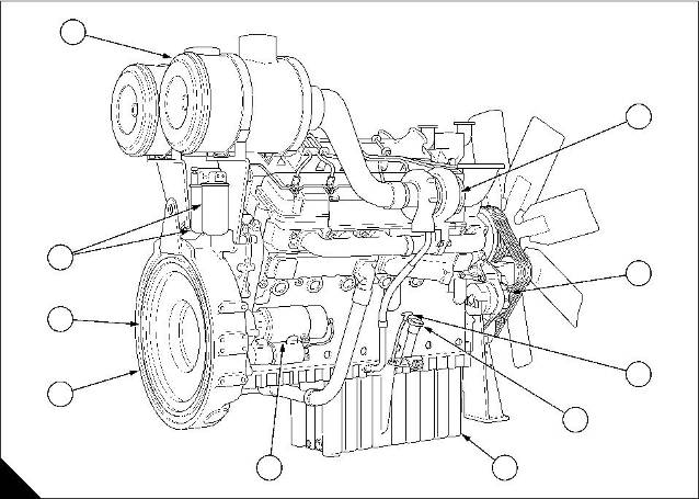
2 Rear and right side view of the 3012 engine |
|
1 ‘A’ bank turbocharger 2 Alternator |
|
6 Starter motor |
|
7 Flywheel housing 8 Flywheel |
|
3 Dipstick |
|
4 Filler cap for lubricating oil 5 Lubricating oil sump |
|
9 Canisters of the fuel filter 10 ‘A’ bank air cleaner |
|
10 |
|
1 |
|
9 8 |
|
2 3 |
|
7 |
|
4 |
|
6 |
|
5 |
|
B |
|
483 |
|
10 |
|
This document has been printed from SPI². Not for Resale |
![]()
![]()
|
3 |
|
Operation instructions |
|
3 |
|
Preparations for a new or an overhauled engine |
|
Every new engine supplied by Perkins Engines Company Limited, Shrewsbury, is run-in before it leaves the factory. |
|
1 |
|
1 Check that all protection covers and blanking plugs have been removed. |
|
2 Fit all components that were removed for storage or for transport. |
|
3 Ensure that drain plugs for coolant and for lubricating oil are securely fitted. |
|
4 Where necessary, connect the remote control linkages, the pressure gauge pipes, the air inlet pipes and the wiring loom. |
|
2 |
|
A |
|
57 |
|
5 Connect the fuel pipes. |
|
6 Connect the exhaust pipes. |
|
7 Fill the fuel tank(s) with the correct grade of fuel |
|
(see page 31). |
|
1 |
|
8 Fill the cooling system with the approved coolant |
|
mixture (see page 31). |
|
9 Fill the sump to the H mark on the dipstick with the correct grade of lubricating oil (see page 32). |
|
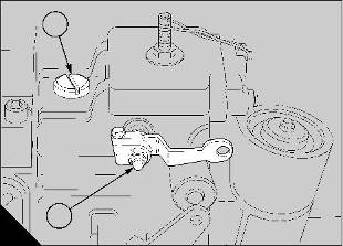
10 Clean the area around the plug (A1) on the |
|
governor housing of the injection pump and remove |
|
1 |
|
the plug. Add approximately 0,2 litres ( / pint) of |
|
3 |
|
clean engine oil of the correct grade (see page 32) to the governor housing. Fit and tighten the plug securely. |
|
B |
|
58 |
|
11 Add oil to the turbochargers as follows: Clean the area around the blanking plug (B1) on the bearing |
|
housing of each turbocharger. Remove the plugs (B1) |
|
1 |
|
and add 0,2 litre ( / pint) of engine oil of the correct |
|
3 |
|
grade to each turbocharger. Fit and tighten the plugs. |
|
12 Eliminate air from the fuel system (see page 27). |
|
13 Lubricate all of the control linkages and check the linkages for free movement. |
|
11 |
|
This document has been printed from SPI². Not for Resale |
![]()
![]()
|
3 How to start a new or overhauled engine or an engine which has been in storage |
|
Prepare to start the engine as given in paragraphs 1 to 13 on page 11. |
|
If an engine has been in storage for a period of more than one month, add clean lubricating oil to the fuel injection pump and to the turbochargers. If the engine has been in storage for less than one month, but the fuel injection pump has been removed and fitted, add lubricating oil to the fuel injection pump. The procedure is described on page 11, paragraphs 10 and 11. Use clean engine oil of the same grade and specification as that already in the system. |
|
Start procedure |
|
Ensure that the stop control is in the STOP position and that the speed control lever is in the IDLE position. Press the start button for 10 seconds and then release it for 10 seconds, then press it for 20 seconds and release it for 20 seconds. Oil pressure MUST be indicated on the gauge. Move the stop control lever to the RUN position and proceed as for a normal start. |
|
12 |
|
This document has been printed from SPI². Not for Resale |
![]()
![]()
|
3 |
|
Normal start procedures |
|
Precautions |
|
Service checks each day before first engine start |
|
The precautions that follow will help to ensure a long and fault-free life for the engine: |
|
1 Check that the level of coolant is just at the bottom of the filler extension in the radiator. Fill, if necessary, to the required level with the approved coolant mixture. If there is a large loss of coolant find the reason. |
|
Variable speed engines |
|
1 Do not operate the engine at high speeds and loads until the coolant has reached a minimum temperature of 78°C. |
|
2 Check the engine oil level. With the engine stopped the oil level must be at the H mark on the dipstick. If necessary, add oil of the same grade and specification as that already in the system. Do NOT add more oil than is necessary. |
|
2 Do not allow the engine to run at idle speed for prolonged periods. |
|
3 Do not exceed the maximum no load speed. |
|
4 Never allow an engine to continue to run if the oil pressure is below 170 kN/m² (25 lbf/in²) at rated speed. |
|
3 Ensure that the fuel tank is full. 4 Check the air restriction indicator. |
|
5 Fill the fuel tank(s) at the end of each day to prevent condensation. |
|
Caution: If a fuel injection pump or turbocharger has been removed from an engine, it must be primed with clean engine oil of the correct grade before the engine is first started. See page 11, paragraphs 10 and 11. |
|
Constant speed engines |
|
1 Do not operate the engine with a full load until the coolant has reached a minimum temperature of 78°C. |
|
Variable speed engines |
|
2 Do not allow the engine to run with no load for prolonged periods. |
|
Perform the daily service checks then proceed as follows: |
|
3 Ensure that the fuel tank(s) are full to prevent condensation. |
|
Turn on the fuel supply. |
|
Move the stop control to the RUN position. |
|
Move the speed control lever to the maximum speed How to stop the engine position. |
|
Variable speed engines |
|
Press the start button and release it when the engine |
|
starts. |
|
1 Put the gear lever into the NEUTRAL position. |
|
2 Operate the engine at approximately 800 rev/min for 3 minutes to allow the turbochargers to reduce speed and temperature. |
|
Move the speed control lever to the idle position. Constant speed engines |
|
Perform daily service checks then proceed as follows: Turn on the fuel supply. |
|
3 Move the stop control to the STOP position. |
|
Constant speed engines |
|
Move the stop control to the RUN position. |
|
1 Operate the engine for 3 minutes at idle speed with no load to allow the turbochargers to reduce speed and temperature. |
|
Press the start button and release it when the engine starts. |
|
2 Move the switches for the engine protection |
|
devices to the OFF position. |
|
How to start the engine in low ambient temperatures |
|
3 Move the stop control to the STOP position. 4 Turn off the fuel supply. |
|
An excess fuel device, within the fuel injection pump, works as a starting aid when ambient temperatures are below 0°C. |
|
Before the engine is started, push fully in, the control rod of the excess fuel device. Press the start button and release it when the engine starts. The control rod returns automatically to its original position when the engine starts. |
|
Caution: The excess fuel device must not be used at the same time as other cold starting aids as the extra fuel will make the engine more difficult to start. |
|
13 |
|
This document has been printed from SPI². Not for Resale |
![]()
![]()
|
This document has been printed from SPI². Not for Resale |
|
4 |
|
Preventive maintenance |
|
4 |
|
Preventive maintenance periods |
|
These preventive maintenance periods apply to average conditions of operation. Check the periods |
|
given by the manufacturer of the equipment in which the engine is installed. If necessary, use the shorter periods. When the operation of the engine must conform to the local regulations, these periods and procedures may need to be adapted to ensure correct operation of the engine. , |
|
The service intervals can be reduced for operation in adverse conditions. The intervals must not be extended unless Perkins Engines Company Limited have approved the changes as indicated in the Perkins Warranty. It is good preventive maintenance to check for leakage and loose fasteners at each service. These maintenance periods apply only to engines that are operated with fuel and lubricating oil which conform to the specifications given in this handbook. |
|
15 |
|
This document has been printed from SPI². Not for Resale |
![]()
![]()
|
4 Schedule for engines in normal use |
|
The preventive maintenance operations must be applied at the interval (hours or months) which occurs first. A - Every 10 hours or daily |
|
B - Every 400 hours or 12 months |
|
C - Every 1200 hours or 24 months |
|
A |
|
B |
|
C |
|
Operation |
|
Check the amount of coolant |
|
Check the level of the lubricating oil |
|
Check the restriction indicators for the air filters and, when necessary, renew the filter elements |
|
Drain the water/sediment from the primary fuel filter Check the condition and the tension of all drive belts Check the specific gravity and the pH value of the coolant Renew the lubricating oil |
|
Renew the canisters of the lubricating oil filter Renew the canister of the main fuel filter |
|
Clean the primary fuel filter |
|
Ensure that the mounting nuts for the turbochargers are tightened securely Check that the air charge cooler and the radiator are clean and free from debris Check the timing of the fuel injection pump |
|
Check that the drive coupling bolts of the fuel injection pump are tightened to 120 Nm (88 lbf ft) |
|
Ensure that the fuel injectors are checked and corrected or renewed, if necessary* Ensure that the tappet clearances are checked and adjusted, if necessary* |
|
* By a person who has had the correct training. |
|
In addition to the operations listed above, the operations listed below must be applied at 12 month intervals: |
|
Drain and flush the coolant system and renew the coolant mixture Check the turbochargers, ensure that they are checked and corrected if necessary* Ensure that the alternator is checked and corrected if necessary* |
|
16 |
|
This document has been printed from SPI². Not for Resale |
![]()
![]()
![]()
![]()
![]()
![]()
![]()
![]()
![]()
![]()
![]()
![]()
![]()
![]()
![]()
![]()
![]()
![]()
![]()
![]()
![]()

|
4 |
|
Schedule for engines in intermittent use |
|
For engines which are in use for a total of less than 400 hours in every twelve months, the schedule below must be used: |
|
The preventive maintenance operations must be applied at the interval (hours or months) which occurs first. |
|
A - Monthly |
|
B - Every 200 hours or 12 months C - Every 1000 hours or 24 months |
|
A |
|
B |
|
C |
|
Operation |
|
Check the amount of coolant |
|
Check the level of the lubricating oil |
|
Check the restriction indicators for the air filters and, when necessary, renew the filter elements |
|
Start and run the engine with 30% load (minimum), until normal temperature of operation is reached |
|
Drain the water/sediment from the primary fuel filter Check the condition and the tension of all drive belts Check the specific gravity and the pH value of the coolant Renew the lubricating oil |
|
Renew the canisters of the lubricating oil filter Renew the canister of the main fuel filter |
|
Clean the primary fuel filter |
|
Ensure that the mounting nuts for the turbochargers are tightened securely Check the timing of the fuel injection pump |
|
Check that the drive coupling bolts of the fuel injection pump are tightened to 120 Nm (88 lbf ft) |
|
Ensure that the fuel injectors are checked and corrected or renewed, if necessary* Ensure that the tappet clearances are checked and adjusted, if necessary* |
|
* By a person who has had the correct training. |
|
In addition to the operations listed above, the operations listed below must be applied at 12 month intervals: |
|
Drain and flush the coolant system and renew the coolant mixture |
|
Check the turbochargers, ensure that they are checked and corrected if necessary* Check that the air charge cooler and the radiator are clean and free from debris Ensure that the alternator is checked and corrected if necessary* |
|
17 |
|
This document has been printed from SPI². Not for Resale |
![]()
![]()
![]()
![]()
![]()
![]()
![]()
![]()
![]()
![]()
![]()
![]()
![]()
![]()
![]()
![]()
![]()
![]()
![]()
![]()
![]()
![]()

|
4 Coolant level |
|
Remove the filler cap from the radiator and check that the level of the coolant mixture just touches the bottom of the filler tube inside the radiator. If necessary, add coolant until the level of the coolant reaches the filler tube. Fit the filler cap. |
|
Caution: If coolant is added to the system during service, it must consist of the same original mixture as used to fill the system. |
|
Warning! On a hot engine release the filler cap carefully as the system will be under pressure. |
|
Lubricating oil level |
|
At the periods given in the service schedule use the dipstick to check the amount of lubricating oil in the sump. While the engine runs, the oil level must be above the L mark. With the engine stopped the oil level must be at the H mark on the dipstick. If necessary, put more oil into the sump. Use the same grade and specification as that already in the system. Do NOT overfill. |
|
18 |
|
This document has been printed from SPI². Not for Resale |
![]()
![]()
|
4 |
|
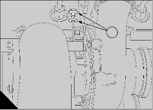
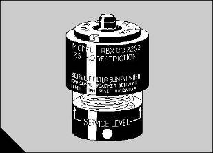
Restriction indicator |
|
Each air filter is fitted with an indicator (A) which gives a visual warning when the filter needs a service. |
|
When the red warning indicator is seen through the clear panel after the engine has stopped, the air filter element must be renewed. |
|
After a clean element has been fitted, press the reset button on the restriction indicator. |
|
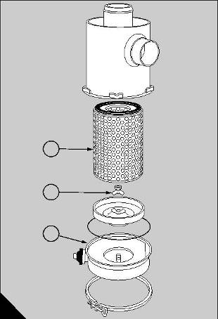
How to renew the elements of the air filters |
|
A |
|
37 |
|
The two air filters (B) contain paper elements. These must not be washed. Renew the paper elements as follows: |
|
1 Loosen the clamp and remove the end cover (B1). Remove the wing nut (B2), withdraw and discard the filter element (B3). |
|
2 Clean, thoroughly, the inside of the casing of the air filter. Fit a new filter element and fit the end cover. |
|
3 Reset the restriction indicator. |
|
Repeat this procedure for the other air filter. |
|
How to drain the primary fuel filter |
|
3 |
|
1 Remove the drain plug from the base of the filter bowl and allow any water or sediment to drain from the unit. |
|
2 1 |
|
2 Fit the drain plug and tighten it securely. |
|
B |
|
21 |
|
19 |
|
This document has been printed from SPI². Not for Resale |
![]()
![]()
|
4 How to check the drive belts |
|
Check all drive belts and renew a belt if it is worn or damaged. Where more than one belt is used between two pulleys, all of the belts must be renewed together. Maximum belt life will be obtained only if the belts are kept at the correct tensions. |
|
1 2 |
|
Check the belt tension at the centre of the longest free length, for example, position (A5) to check the fan drive belts. |
|
5 |
|
Use a ‘Gates "Krikit" V-belt tension gauge’ or similar |
|
tool to check the tension of the belts. |
|
4 |
|
3 |
|
A |
|
The correct tension for all belts is 400 to 489 N (90 to 100 lbf). Where more than one belt is used between two pulleys, check/adjust the tension on the tightest belt. |
|
59 |
|
Note: When new belts are fitted they must be checked again after the engine has been run for 15 minutes and, if necessary, adjusted to the correct tension. |
|
1 |
|
How to adjust the tension of the fan belts |
|
1 To adjust the tension of the fan belts, loosen the nuts on the adjustment bolt. Loosen the large lock nut (B1) on the belt tensioner and turn the adjustment bolt (B2) until the correct tension is obtained. |
|
2 |
|
B |
|
2 Tighten the lock nut and check the tension of the |
|
60 |
|
belts again. |
|
How to renew the alternator belt |
|
3 Run the engine for 15 minutes and then check the |
|
belt tension again. |
|
1 Remove the fan belts from the crankshaft pulley as given on this page. |
|
Check the tension of new belts every week for four weeks and then at the intervals specified in the service schedule |
|
2 Loosen the adjustment bolts to release the tension on the alternator belt and remove the old belt. Check that the pulley grooves are clean and fit a new belt. Adjust the belt to the correct tension. Fit the fan belts as given on this page. |
|
How to adjust the tension of the alternator belt |
|
1 Loosen the alternator pivot bolt (A1), the adjustment link bolt (A3) and the adjustment bolt (A2). Move the alternator to obtain the correct belt tension and tighten the bolts. |
|
2 Run the engine for 15 minutes and then check the belt tension again. |
|
Check the tension of new belts every week for four weeks and then at the intervals specified in the service schedule. |
|
How to renew the fan belts |
|
1 To renew the fan belts, remove the six bolts which fasten the fan to the pulley and push the fan forward into the radiator cowl. |
|
2 Release the tension on the belts and remove the old belts. Ensure that the pulley grooves are free from grease and dirt. Fit a new set of belts. |
|
3 Fit the fan and tighten the bolts securely. Adjust the fan belts to the correct tension. |
|
20 |