 English
 Espaol
 Franais
 阿拉伯
阿拉伯 中文
中文 Deutsch
 Italiano
 Português
 日本
日本 韩国
韩国 български
 hrvatski
 esky
esky Dansk
Dansk Nederlands
 suomi
suomi Ελληνικ
 印度
印度 norsk
norsk Polski
 Roman
Roman русский
 Svenska
Perkins珀金斯1000柴油发动机31258185风扇供应商,Perkins珀金斯1000柴油发动机31258185风扇技术价格规格咨询服务,Perkins珀金斯1000柴油发动机31258185风扇零配件供应,Perkins珀金斯1000柴油发动机31258185风扇售后服务中心,Perkins珀金斯1000柴油发动机31258185风扇,Perkins珀金斯1000柴油发动机31258185风扇详细的技术参数,

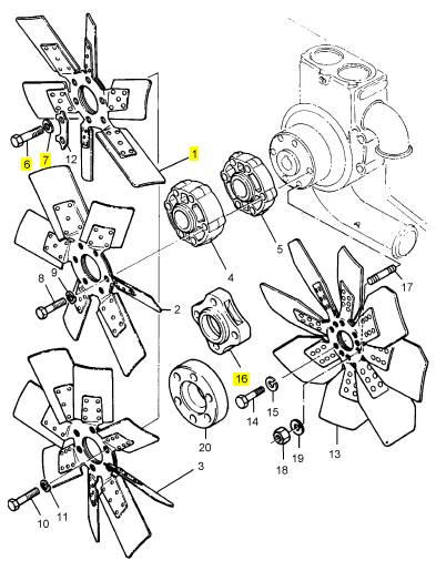
Perkins珀金斯1000柴油发动机31258185风扇
详细描述
项目 零配件号码 最新件号 描述
1 31258185 1 31258185 风扇
6 0746259 4 0746259 螺旋
7 0920053 4 0920053 垫圈
16 3748 W201 1 3748 W202 伸长
项目 零配件号码 最新件号 描述
3 2614 B656 1 2614 B656 带
6 38167161 1 38167161 托架
7 0826264 1 0826264 图钉
8 33134427 1 33134427 间隔器
9 36151505 1 36151505 垫圈
10 0576002 1 0576002 螺帽
11 0920003 1 0920003 垫圈
12 0920053 1 0920053 垫圈
13 0826264 1 0826264 图钉
14 33134427 1 33134427 间隔器
15 36151505 1 36151505 垫圈
16 0576002 1 0576002 螺帽
17 0920003 1 0920003 垫圈
18 0920053 1 0920053 垫圈
19 0746456 1 0746456 螺旋
20 0920004 1 0920004 垫圈
21 0920054 1 0920054 垫圈
22 2184467 1 2184467 螺拴
23 33283509 1 33283509 衬套
24 0920006 1 0920006 垫圈
25 0920006 1 0920006 垫圈
26 0920055 1 0920055 垫圈
28 0746459 1 0746459 螺旋
29 0576051 1 0576051 螺帽
30 0920004 1 0920004 垫圈
31 0920004 1 0920004 垫圈
32 0920054 1 0920054 垫圈
33 36154105 1 36154105 板
34 0746456 1 0746456 螺旋
35 0576051 1 0576051 螺帽
36 33135119 1 33135119 间隔器
37 0920054 1 0920054 垫圈
38 33134427 2 33134427 间隔器
39 0746257 2 0746257 螺旋
|
KENR6906 |
|
57 Disassembly and Assembly Section |
|
NOTICE Keep all parts clean from contaminants. |
|
Contaminants may cause rapid wear and shortened component life. |
|
g01397091 |
|
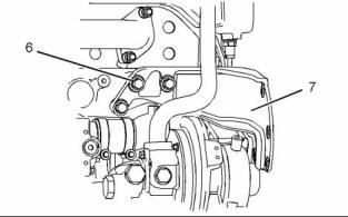
Illustration 128 |
|
6. If necessary, follow Steps 6.a and 6.b in order to remove the support bracket. |
|
a. Remove bolts (6). |
|
g01386146 |
|
Illustration 126 |
|
b. Remove support bracket (7). |
|
i02767679 |
|
Front Plate - Install |
|
Installation Procedure |
|
NOTICE Keep all parts clean from contaminants. |
|
Contaminants may cause rapid wear and shortened component life. |
|
g01397095 |
|
Illustration 127 |
|
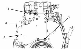
1. Remove bolts (3) (not shown) that secure plate (4) to the support bracket. |
|
2. Remove nuts (1). |
|
3. Support the weight of plate (4). The weight of the plate is approximately 25 kg (55 lb). |
|
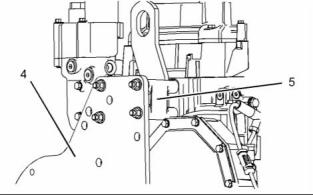
4. Remove nuts (2) and remove plate (4). |
|
5. Remove spacer (5) from the cylinder head. Note the routing of the wiring harness between the spacer and the cylinder head. |
|
g01397091 |
|
Illustration 129 |
|
1. If support bracket (7) was removed, position the support bracket on the cylinder block and install bolts (6) finger tight. |
|
This document has been printed from SPI². Not for Resale |
![]()
![]()
![]()
![]()
![]()
![]()
![]()
![]()
![]()

|
58 |
|
KENR6906 |
|
Disassembly and Assembly Section |
|
b. Install the belt tightener. Refer to Disassembly and Assembly, “Belt Tightener - Install”. |
|
i02754819 Crankcase Breather - Remove and Install |
|
(Closed Breather) |
|
Removal Procedure |
|
g01397095 |
|
Illustration 130 |
|
NOTICE |
|
Keep all parts clean from contaminants. |
|
Contaminants may cause rapid wear and shortened component life. |
|
NOTICE |
|
Care must be taken to ensure that fluids are contained during performance of inspection, maintenance, test- ing, adjusting and repair of the product. Be prepared to collect the fluid with suitable containers before open- ing any compartment or disassembling any compo- nent containing fluids. |
|
Dispose of all fluids according to local regulations and mandates. |
|
g01386146 |
|
Illustration 131 |
|
2. Install spacer (5) to the cylinder head. |
|
Note: Ensure the correct routing of the wiring harness around the spacer. |
|
3. Position plate (4) on the studs and install nuts (1) and (2). |
|
4. Tighten nuts (1) and (2) to a torque of 100 N·m (74 lb ft). |
|
5. Install bolts (3) (not shown) finger tight. |
|
6. If support bracket (7) was removed, tighten bolts (6) to a torque of 55 N·m (41 lb ft). Refer to Illustration 129. |
|
7. Tighten bolts (3) (not shown) to a torque of 55 N·m (41 lb ft). |
|
Note: Ensure that the plate is not stressed as the |
|
bolts are tightened. |
|
g01401970 |
|
Illustration 132 |
|
End By: |
|
1. Loosen the clamp and disconnect hose (1) from |
|
crankcase breather (4). |
|
a. Install the fan drive. Refer to Disassembly and |
|
Assembly, “Fan Drive - Install”. |
|
2. Loosen the clamp and disconnect hose (3) from |
|
crankcase breather (4). |
|
This document has been printed from SPI². Not for Resale |
![]()
![]()
![]()
![]()
![]()
![]()
![]()
![]()

|
KENR6906 |
|
59 Disassembly and Assembly Section |
|
3. Disconnect hose (5) from crankcase breather (4). |
|
i02790384 Crankcase Breather - Remove and Install |
|
4. Remove bolts (2) and remove crankcase breather (4) from the mounting bracket. |
|
(Open Breather) |
|
5. If necessary, disassemble crankcase breather (4). Refer to Operation and Maintenance Manual, “Engine Crankcase Breather - Replace” for the correct procedure. |
|
Removal Procedure |
|
Installation Procedure |
|
NOTICE |
|
Keep all parts clean from contaminants. |
|
NOTICE |
|
Keep all parts clean from contaminants. |
|
Contaminants may cause rapid wear and shortened component life. |
|
Contaminants may cause rapid wear and shortened component life. |
|
g01401675 |
|
Illustration 134 |
|
g01401970 |
|
Illustration 133 |
|
1. Remove bolt (2), clip (3) and spacer (4). |
|
1. Ensure that hoses (1), (3) and (5) are clean and free from restriction. |
|
2. Loosen the hose clamp and remove hose (1) from the valve mechanism cover base. |
|
2. If necessary, assemble crankcase breather (4). Refer to Operation and Maintenance Manual, “Engine Crankcase Breather - Replace” for the correct procedure. |
|
Installation Procedure |
|
NOTICE |
|
Keep all parts clean from contaminants. |
|
3. Position crankcase breather (4) on the mounting bracket and install bolts (2). Tighten the bolts to a torque of 28 N·m (21 lb ft). |
|
Contaminants may cause rapid wear and shortened component life. |
|
4. Connect hose (5) to crankcase breather (4). Tighten the nut securely. |
|
5. Connect hose (3) to crankcase breather (4). Tighten the clamp securely. |
|
6. Connect hose (1) to crankcase breather (4). Tighten the clamp securely. |
|
This document has been printed from SPI². Not for Resale |