 English
 Espaol
 Franais
 阿拉伯
阿拉伯 中文
中文 Deutsch
 Italiano
 Português
 日本
日本 韩国
韩国 български
 hrvatski
 esky
esky Dansk
Dansk Nederlands
 suomi
suomi Ελληνικ
 印度
印度 norsk
norsk Polski
 Roman
Roman русский
 Svenska
Perkins珀金斯900 3.152柴油发动机3142 A081排气阀/ZZ80235汽缸盖总成供应商,Perkins珀金斯900 3.152柴油发动机3142 A081排气阀/ZZ80235汽缸盖总成技术价格规格咨询服务,Perkins珀金斯900 3.152柴油发动机3142 A081排气阀/ZZ80235汽缸盖总成零配件供应,Perkins珀金斯900 3.152柴油发动机3142 A081排气阀/ZZ80235汽缸盖总成售后服务中心,Perkins珀金斯900 3.152柴油发动机3142 A081排气阀/ZZ80235汽缸盖总成,Perkins珀金斯900 3.152柴油发动机3142 A081排气阀/ZZ80235汽缸盖总成详细的技术参数,

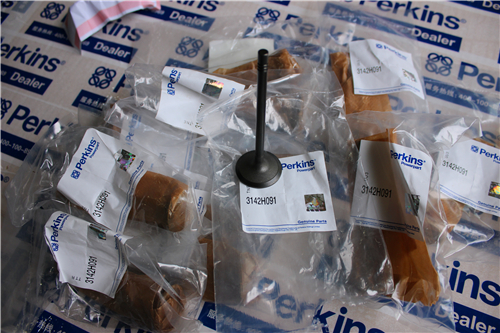
Perkins珀金斯900 3.152柴油发动机3142 A081排气阀/ZZ80235汽缸盖总成
详细描述
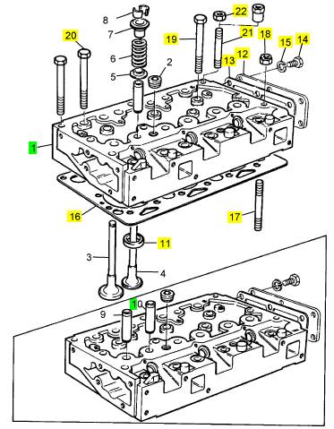
项目 零配件号码 最新件号 描述
3142 A081 3 3142 A081 排气阀
1 ZZ80235 1 ZZ80235 汽缸盖总成
(1) ZZ80235P 1 ZZ80235R 汽缸盖总成 -EXCH
11 33124428 3 33124428 阀座气门座圈
12 1 盖
13 1 接合
14 6 螺旋
15 6 垫圈
16 3681 E024 1 3681 E024 汽缸盖垫片
17 32524132 1 32524132 图钉
18 33221329 1 33221329 螺帽
19 32181457 5 32181457 汽缸盖螺拴
20 32181458 9 32181458 汽缸盖螺拴
21 32524148 3 32524148 图钉
22 33221329 3 33221329 螺帽
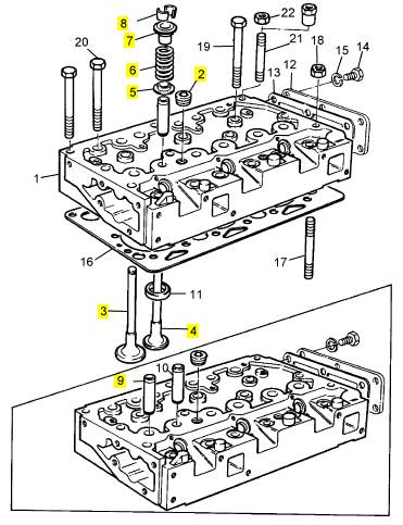
项目 零配件号码 最新件号 描述
ZZ80017 1 检查历史 汽缸盖总成
2 2431154 2 2431154 栓塞
2 2431154 2 2431154 栓塞
3 31431681 3 31431681 进气阀
4 31431031 3 31431031 排气阀
5 33415133 6 33415133 弹簧塾圈
6 0780012 6 0780012 阀弹簧
7 33423148 6 33423148 帽
8 0230001 12 0230001 阀筒夹
8 0230001 6 0230001 阀筒夹
9 U3316A031 3 3316 A031 气门导管
10 U3313E734 3 3313 E734 气门导管
|
Disassembly and Assembly Section |
|
g01383260 |
|
g01383261 |
|
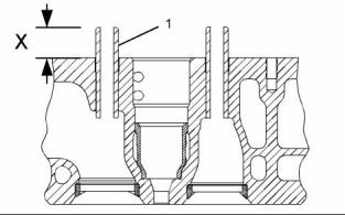
Illustration 42 |
|
Illustration 44 |
|
1. Use Tooling (A) and a hammer in order to remove the valve guides from the cylinder head. |
|
2. Use Tooling (A) and Tooling (B) to install valve guides (1) in the cylinder head. |
|
Installation Procedure |
|
Note: Tooling (B) must be used in order to install the valve guides to the correct height. |
|
Table 13 |
|
Height (X) from the top of the valve guide to the cylinder head surface ................ 35.00 ± 0.50 mm (1.378 ± 0.020 inch) |
|
Required Tools |
|
Tool A |
|
Part Number CVT0001 |
|
Part Description Valve Guide Driver Valve Guide Collar |
|
Qty 1 |
|
For more information, refer to Specifications, “Cylinder Head Valves”. |
|
B |
|
CVT0002 |
|
1 |
|
End By: |
|
NOTICE |
|
Keep all parts clean from contaminants. |
|
a. Install the inlet and exhaust valves. Refer to Disassembly and Assembly, “Inlet and Exhaust Valves - Remove and Install”. |
|
Contaminants may cause rapid wear and shortened component life. |
|
i02754779 Engine Oil Filter Base - Remove |
|
1. Lubricate the parent bores for the valve guides in the cylinder head with clean engine oil. |
|
Removal Procedure |
|
NOTICE Keep all parts clean from contaminants. |
|
Contaminants may cause rapid wear and shortened component life. |
|
g01383265 |
|
Illustration 43 |
|
This document has been printed from SPI². Not for Resale |
![]()
![]()

![]()
![]()
![]()

![]()
![]()
![]()
|
KENR6906 |
|
25 Disassembly and Assembly Section |
|
NOTICE |
|
Care must be taken to ensure that fluids are contained during performance of inspection, maintenance, test- ing, adjusting and repair of the product. Be prepared to collect the fluid with suitable containers before open- ing any compartment or disassembling any compo- nent containing fluids. |
|
Dispose of all fluids according to local regulations and mandates. |
|
1. Place a suitable container below the engine oil filter base in order to drain the engine oil. |
|
g01401581 |
|
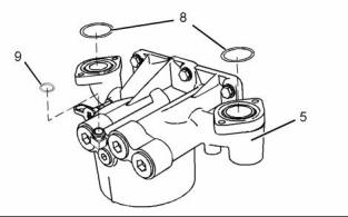
Illustration 46 |
|
9. Remove O-ring seals (8) and O-ring seal (9) from engine oil filter base (5). |
|
g01404137 |
|
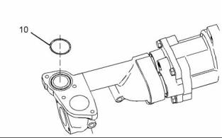
Illustration 47 |
|
10. Remove O-ring seal (10) from the engine oil pump. |
|
g01396094 |
|
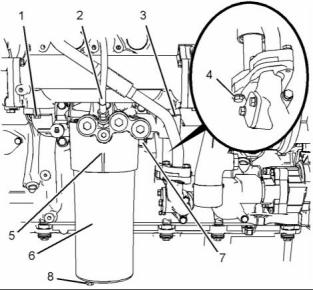
Illustration 45 |
|
2. Remove plug (8). Allow the engine oil to drain. |
|
i02754781 Engine Oil Filter Base - Disassemble |
|
3. Remove engine oil filter (6) from engine oil filter base (5). Remove the O-ring seal and remove the filter element from the engine oil filter. Refer to Operation and Maintenance Manual, “Engine Oil and Filter - Change” for more information. |
|
4. Disconnect hose assembly (2) from engine oil filter base (5). |
|
Disassembly Procedure |
|
5. Remove bolts (1) and (3). |
|
Start By: |
|
6. Remove bolts (4) in order to disconnect the tube assembly from the engine oil pump. |
|
a. Remove the engine oil filter base. Refer to Disassembly and Assembly, “Engine Oil Filter Base - Remove”. |
|
7. Support the weight of the engine oil cooler. The engine oil cooler weighs approximately 23 kg (50 lb). |
|
NOTICE Keep all parts clean from contaminants. |
|
8. Remove engine oil filter base (5) and remove the joint. |
|
Contaminants may cause rapid wear and shortened component life. |
|
This document has been printed from SPI². Not for Resale |
![]()
![]()
![]()
![]()
![]()
![]()
![]()
![]()
|
26 |
|
KENR6906 |
|
Disassembly and Assembly Section |
|
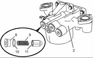
b. Remove spring (9). |
|
c. Remove plunger (11). |
|
Personal injury can result from being struck by parts propelled by a released spring force. |
|
Make sure to wear all necessary protective equip- ment. |
|
Follow the recommended procedure and use all recommended tooling to release the spring force. |
|
g01396108 |
|
Illustration 50 |
|
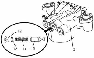
4. Follow Steps 4.a through 4.c in order to remove the oil cooler bypass valve. |
|
a. Remove plug (12) from engine oil filter base (2). Remove O-ring seal (13) from plug (12). |
|
g01380571 |
|
Illustration 48 |
|
b. Remove spring assembly (14). c. Remove plunger (15). |
|
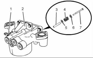
1. If necessary, remove oil sampling valve (1) from engine oil filter base (2). Remove the O-ring seal from the oil sampling valve. |
|
2. Follow Steps 2.a and 2.b in order to remove the high pressure relief valve. |
|
a. Remove bolt (7) from engine oil filter base (2). |
|
b. Remove cap (6), spring (4), seat (5) and sleeve (3) from engine oil filter base (2). |
|
g01396110 |
|
Illustration 51 |
|
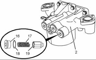
5. Follow Steps 5.a through 5.c in order to remove the oil pump bypass valve. |
|
a. Remove plug (16) from engine oil filter base (2). Remove O-ring seal (18) from plug (16). |
|
b. Remove spring (17). c. Remove plunger (19). |
|
g01396109 |
|
Illustration 49 |
|
3. Follow Steps 3.a through 3.c in order to remove the oil filter bypass valve. |
|
a. Remove plug (8) from engine oil filter base (2). Remove O-ring seal (10) from plug (8). |
|
This document has been printed from SPI². Not for Resale |
![]()
![]()
![]()
![]()
![]()
![]()
![]()
|
KENR6906 |
|
27 Disassembly and Assembly Section |
|
i02754782 |
|
Engine Oil Filter Base - Assemble |
|
Assembly Procedure |
|
NOTICE Keep all parts clean from contaminants. |
|
Contaminants may cause rapid wear and shortened component life. |
|
g01396108 |
|
Illustration 53 |
|
3. Follow Steps 3.a through 3.d in order to install the oil cooler bypass valve. |
|
Improper assembly of parts that are spring loaded can cause bodily injury. |
|
a. Lubricate spring assembly (14), and plunger (15) with clean engine oil. |
|
To prevent possible injury, follow the established assembly procedure and wear protective equip- ment. |
|
b. Install spring assembly (14), and plunger (15) into engine oil filter base (2). |
|
c. Install a new O-ring seal (13) to plug (12). |
|
1. Inspect the components for wear or damage. Replace any components that are worn or damaged. |
|
d. Install plug (12) to engine oil filter base (2). Tighten the plug to a torque of 100 N·m (74 lb ft). |
|
g01396110 |
|
Illustration 52 |
|
g01396109 |
|
Illustration 54 |
|
2. Follow Steps 2.a through 2.d in order to install the oil pump bypass valve. |
|
4. Follow Steps 4.a through 4.d in order to install the oil filter bypass valve. |
|
a. Lubricate plunger (19) and spring (17) with clean engine oil. |
|
a. Lubricate plunger (11) and spring (9) with clean engine oil. |
|
b. Install plunger (19) and spring (17) into engine oil filter base (2). |
|
b. Install plunger (11) and spring (9) into engine oil filter base (2). |
|
c. Install a new O-ring seal (18) to plug (16). |
|
c. Install a new O-ring seal (10) to plug (8). |
|
d. Install plug (16) to engine oil filter base (2). Tighten the plug to a torque of 100 N·m (74 lb ft). |
|
d. Install plug (8) to engine oil filter base (2). Tighten the plug to a torque of 100 N·m (74 lb ft). |
|
This document has been printed from SPI². Not for Resale |