 English
 Espaol
 Franais
 阿拉伯
阿拉伯 中文
中文 Deutsch
 Italiano
 Português
 日本
日本 韩国
韩国 български
 hrvatski
 esky
esky Dansk
Dansk Nederlands
 suomi
suomi Ελληνικ
 印度
印度 norsk
norsk Polski
 Roman
Roman русский
 Svenska
Perkins珀金斯1600柴油发动机1836537 C91温度感应传感器供应商,Perkins珀金斯1600柴油发动机1836537 C91温度感应传感器技术价格规格咨询服务,Perkins珀金斯1600柴油发动机1836537 C91温度感应传感器零配件供应,Perkins珀金斯1600柴油发动机1836537 C91温度感应传感器售后服务中心,Perkins珀金斯1600柴油发动机1836537 C91温度感应传感器,Perkins珀金斯1600柴油发动机1836537 C91温度感应传感器详细的技术参数,

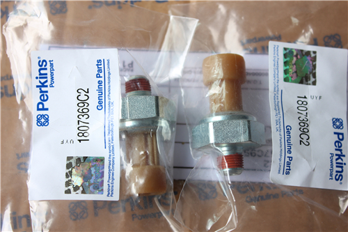
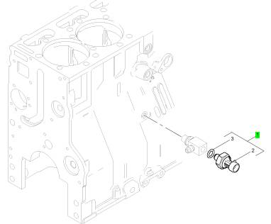
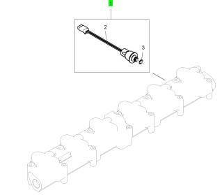
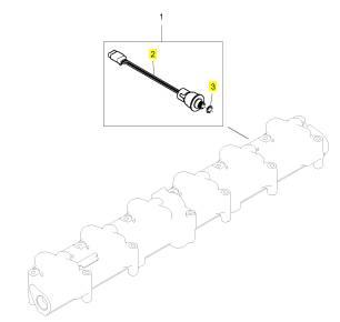
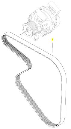
Perkins珀金斯1600柴油发动机1836537 C91感应传感器
详细描述
项目 零配件号码 新件号 描述
1 1836537 C91 1 1836537 C91 温度感应传感器
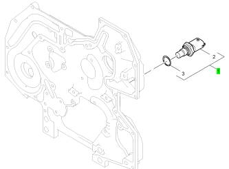
项目 零配件号码 新件号 描述
2 1 温度感应传感器
3 1837799 C1 1 1837799 C1 密封O型圈
项目 零配件号码 新件号 描述
1 1836537 C91 1 1836537 C91 温度感应传感器
项目 零配件号码 新件号 描述
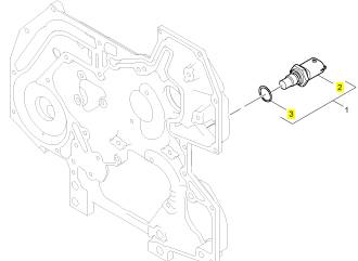
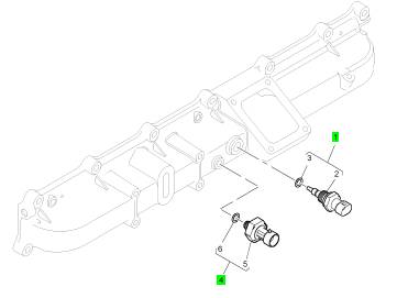
1 1839415 C91 1 1839415 C91 油压感应传感器
项目 零配件号码 新件号 描述
2 1 油压感应传感器
3 1837802 C1 1 1837802 C1 密封O型圈

项目 零配件号码 新件号 描述
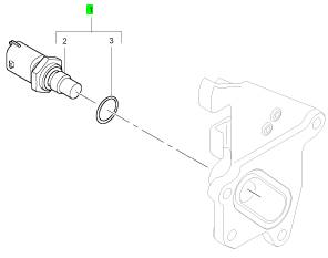
1 1875838 C91 1 1875838 C91 气温感应传感器装备
4 1846481 C92 1 1846481 C92 气压感应传感器装备
项目 零配件号码 新件号 描述
2 1 气温感应传感器
3 1874302 C1 1 1874302 C1 密封 -感应传感器
项目 零配件号码 新件号 描述
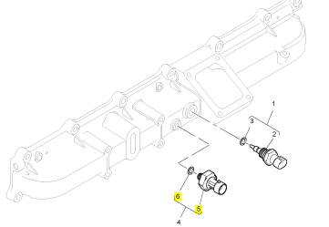
5 1 气压感应传感器
6 1837801 C1 1 1837801 C1 密封 -感应传感器
项目 零配件号码 新件号 描述
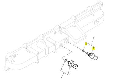
1 1875784 C93 1 1875784 C93 感应传感器
项目 零配件号码 新件号 描述
2 1 感应传感器
3 1837800 C1 1 1837800 C1 密封 -感应传感器
项目 零配件号码 新件号 描述
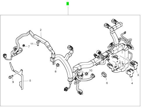
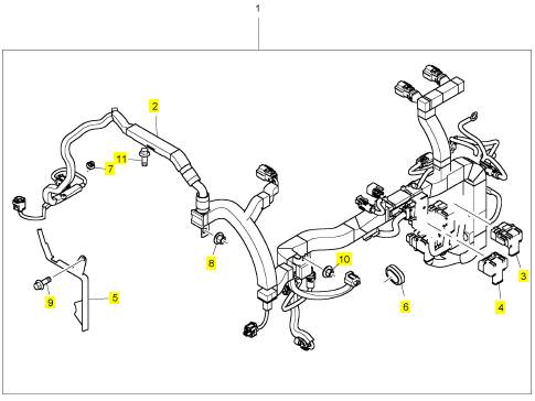
1 1894153 C92 1 7094748 C91 线束
项目 零配件号码 新件号 描述
2 1 线束
3 7080152 C1 4 7080152 C1 盖
4 7080153 C1 1 7080153 C1 盖
5 1880854 C1 1 1880854 C1 托架
6 1878479 C1 1 1878479 C1 密封
7 1881092 C1 4 1881092 C1 承件
8 1877830 C2 1 1877830 C2 螺帽
9 1817956 C1 1 1817956 C1 公制的螺拴
10 1878093 C1 1 1878093 C1 螺帽
11 1817956 C1 1 1817956 C1 公制的螺拴
项目 零配件号码 新件号 描述
1 1847706 C1 1 1847706 C1 皮带
|
KENR8772 |
|
79 Testing and Adjusting Section |
|
Table 19 |
|
Specifications 0.05 to 0.13 mm |
|
Liner Projection |
|
(0.00197 to 0.00512 inch) |
|
Maximum Variation in Each Liner |
|
0.03 mm (0.00118 inch) |
|
Maximum Average Variation Between Adjacent Liners |
|
0.03 mm (0.00118 inch) 0.03 mm (0.00118 inch) |
|
Maximum Variation Between All Six Liners |
|
9. If a liner does not meet the recommended cylinder liner projection specification, check the following parts: |
|
• The depth of the cylinder block bore should be 116.421 ± 0.027 mm (4.58349 ± 0.00106 inch). |
|
g00286049 |
|
• The liner flange should be 116.57 to 116.60 mm (4.58936 to 4.59054 inch). |
|
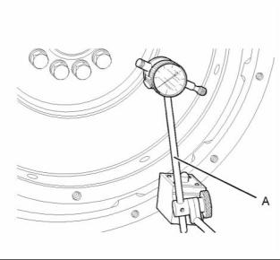
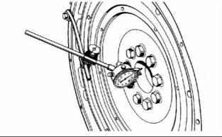
Illustration 66 |
|
Typical example |
|
If the dimensions for the liner flange do not match the specifications, replace the liner. Then repeat the liner projection measurements. If the dimensions for the depth of the cylinder block bore do not match the specifications, replace the cylinder block. Then repeat the liner projection measurements. |
|
1. Install Tooling (A). Refer to illustration 66. Always put a force on the crankshaft in the same direction before the dial indicator is read. This will remove any crankshaft end clearance. |
|
2. Set the dial indicator to read 0.0 mm (0.00 inch). |
|
3. Turn the flywheel at intervals of 45 degrees and |
|
read the dial indicator. |
|
i04032190 |
|
Flywheel - Inspect |
|
4. Take the measurements at all four points. The difference between the lower measurements and the higher measurements that are performed at all four points must not be more than 0.20 mm (0.008 inch), which is the maximum permissible face runout (axial eccentricity) of the flywheel. |
|
Face Runout (Axial Eccentricity) of the Flywheel |
|
Bore Runout (Radial Eccentricity) of the Flywheel |
|
Table 20 |
|
Required Tools |
|
Table 21 |
|
Tool |
|
Part Number 21825617 - |
|
Part Description Dial Gauge |
|
Qty 1 |
|
Required Tools |
|
A |
|
Tool |
|
Part Number 21825617 - |
|
Part Description Dial Gauge |
|
Qty 1 |
|
Holder |
|
1 |
|
A |
|
Magnetic Base |
|
1 |
|
This document is printed from SPI². Not for RESALE |
![]()

![]()

|
80 |
|
KENR8772 |
|
Testing and Adjusting Section |
|
i04032193 |
|
Flywheel Housing - Inspect |
|
Table 22 |
|
Required Tools Part Number Part Description |
|
Tool |
|
Qty |
|
21825617 - |
|
Dial Gauge Holder |
|
1 |
|
A |
|
Face Runout (Axial Eccentricity) of the Flywheel Housing |
|
g01278054 |
|
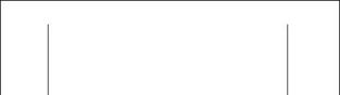
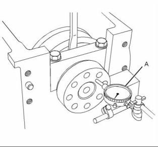
Illustration 67 |
|
Typical example |
|
1. Install Tooling (A). Refer to illustration 67. |
|
2. Set the dial indicator to read 0.0 mm (0.00 inch). |
|
3. Turn the flywheel at intervals of 45 degrees and read the dial indicator. |
|
4. Take the measurements at all four points. The difference between the lower measurements and the higher measurements that are performed at all four points must not be more than 0.20 mm (0.008 inch) for the maximum permissible face runout (radial eccentricity) of the flywheel. |
|
g00285931 |
|
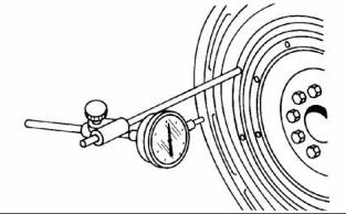
Illustration 69 |
|
Typical example |
|
If you use any other method except the method that is given here, always remember that the bearing clearance must be removed in order to receive the correct measurements. |
|
1. Install Tooling (A) to the flywheel so the anvil of the dial indicator will contact the face of the flywheel housing. Refer to illustration 69. |
|
2. Use a rubber mallet and tap the crankshaft toward the rear before the dial indicator is read at each point. |
|
g00286058 |
|
Illustration 68 |
|
Flywheel clutch pilot bearing bore |
|
5. To find the runout (eccentricity) of the pilot bearing bore, use the preceding procedure. |
|
6. The runout (eccentricity) of the bore for the pilot bearing in the flywheel must not exceed 0.13 mm (0.005 inch). |
|
This document is printed from SPI². Not for RESALE |
![]()
![]()
![]()
![]()
|
KENR8772 |
|
81 Testing and Adjusting Section |
|
g00285932 |
|
g00285932 |
|
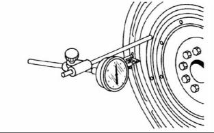
Illustration 70 |
|
Illustration 72 |
|
Checking face runout of the flywheel housing |
|
Checking bore runout of the flywheel housing |
|
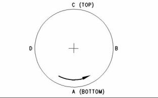
3. Turn the flywheel while the dial indicator is set at 0.0 mm (0.00 inch) at location (A). Read the dial indicator at locations (B), (C), and (D). |
|
2. Turn the flywheel while the dial indicator is set at 0.0 mm (0.00 inch) at location (A). Read the dial indicator at locations (B), (C), and (D). |
|
4. The difference between the lower measurements and the higher measurements that are performed at all four points must not be more than 0.3 mm (0.01181 inch), which is the maximum permissible face runout (axial eccentricity) of the flywheel housing. |
|
3. The difference between the lower measurements and the higher measurements that are performed at all four points must not be more than 0.3 mm (0.01181 inch), which is the maximum permissible face runout (axial eccentricity) of the flywheel housing. |
|
Bore Runout (Radial Eccentricity) of the Flywheel Housing |
|
i04201129 |
|
Crankshaft Thrust - Measure |
|
Table 23 |
|
Required Tools |
|
Tool |
|
Part Number |
|
Part Description |
|
QTY |
|
A |
|
21825617 |
|
Dial Indicator Group |
|
1 |
|
A thrust washer is installed on either side of the rear main bearing. The thrust washer controls the end play of the crankshaft. |
|
g00285934 |
|
Illustration 71 |
|
Force the crankshaft toward the front of the engine and back to the rear of the engine. |
|
Typical example |
|
1. Install Tooling (A) to the flywheel so the anvil of the dial indicator will contact the bore of the flywheel housing. Refer to illustration 71. |
|
This document is printed from SPI². Not for RESALE |
![]()
![]()

![]()
![]()
|
82 |
|
KENR8772 |
|
Testing and Adjusting Section |
|
g02390536 |
|
g02390556 |
|
Illustration 73 |
|
Illustration 74 |
|
Typical example |
|
Typical example |
|
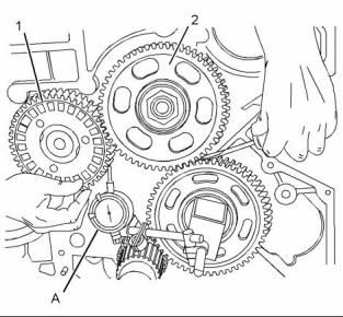
1. Check the end play of the crankshaft with Tooling (A). |
|
2. Use Tooling (A) to measure the backlash between the camshaft gear (1) and the upper idler gear (2). Refer to Specifications, “Gear Group (Front)” for the backlash measurement. |
|
2. To check the tolerance of the crankshaft end play, refer to Specifications, “Crankshaft”. |
|
i04201149 |
|
Gear Group - Inspect |
|
Table 24 |
|
Required Tools |
|
Tool |
|
Part |
|
Part Description |
|
QTY |
|
Number |
|
A |
|
21825617 |
|
Dial Indicator Group |
|
1 |
|
Note: If one or more of the gears need to be removed for repair, refer to Disassembly and Assembly, “Gear Group (Front) - Remove” in order to remove the gears. Refer to Disassembly and Assembly, “Gear Group (Front) - Install” in order to install the gears. |
|
g02390558 |
|
Illustration 75 |
|
Typical example |
|
1. Inspect the gears for wear or for damage. If the gears are worn or damaged, use new parts for replacement. |
|
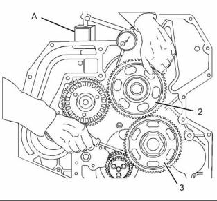
3. Use Tooling (A) to measure the backlash between the upper idler gear (2) and the lower idler gear (3). Refer to Specifications, “Gear Group (Front)” for the backlash measurement. |
|
This document is printed from SPI². Not for RESALE |
![]()
![]()
![]()
![]()
|
KENR8772 |
|
83 Testing and Adjusting Section |
|
g02390559 |
|
g02317733 |
|
Illustration 76 |
|
Illustration 77 |
|
Typical example |
|
Typical example |
|
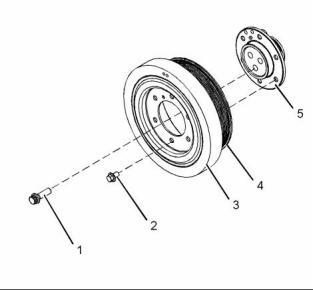
(1) Bolts (2) Bolts (3) Vibration damper (4) Crankshaft pulley (5) Crankshaft adapter |
|
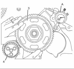
4. Use Tooling (A) to measure the backlash between the lower idler gear (3) and the crankshaft gear (4). Refer to Specifications, “Gear Group (Front)” for the backlash measurement. |
|
Damage to the vibration damper or failure of the vibration damper will increase vibrations. A damaged vibration damper will result in damage to the crankshaft. |
|
i04112355 |
|
Vibration Damper - Check |
|
Replace the damper if any of the following conditions exist: |
|
NOTICE |
|
• The damper is dented or cracked. |
|
Inspect the viscous vibration damper for signs of leak- ing and for signs of damage to the case. Either of these conditions can cause the weight to contact the case. This contact can affect damper operation. |
|
• The paint on the damper is discolored from excessive heat. |
|
• The damper is bent. |
|
• The bolt holes are worn or there is a loose fit for the bolts. |
|
• The engine has had a crankshaft failure due to torsional forces. |
|
Check the areas around the holes for the bolts in the vibration damper for cracks or for wear and for damage. |
|
Use the following steps in order to check the alignment and the runout of the vibration damper: |
|
1. Remove any debris from the front face of the vibration damper. Remove any debris from the circumference of the vibration damper. |
|
This document is printed from SPI². Not for RESALE |
![]()
![]()
![]()
![]()
![]()
|
84 |
|
KENR8772 |
|
Testing and Adjusting Section |
|
2. Mount the dial indicator on the front cover. Use the dial indicator to measure the outer face of the vibration damper. Set the dial indicator to read 0.00 mm (0.00 inch). |
|
3. Rotate the crankshaft at intervals of 45 degrees and read the dial indicator. |
|
4. The difference between the lower measurements and the higher measurements that are read on the dial indicator at all four points must not be more than 0.0127 mm (0.0005 inch). |
|
If the reading on the dial indicator is more than 0.0127 mm (0.0005 inch), inspect the pulley and the vibration damper for damage. If the pulley or the vibration damper are damaged, use new parts for replacement. |
|
This document is printed from SPI². Not for RESALE |
![]()
|
KENR8772 |
|
85 Testing and Adjusting Section |
|
Electrical System Alternator - Test |
|
i02418531 |
|
1. Put the positive lead “+” of a suitable multimeter on the “B+” terminal of the alternator. Put the negative “-” lead on the ground terminal or on the frame of the alternator. Put a suitable ammeter around the positive output wire of the alternator. |
|
2. Turn off all electrical accessories. Turn off the fuel to the engine. Crank the engine for 30 seconds. Wait for two minutes in order to cool the starting motor. If the electrical system appears to operate correctly, crank the engine again for 30 seconds. |
|
Note: Cranking the engine for 30 seconds partially discharges the batteries in order to do a charging test. If the battery has a low charge, do not perform this step. Jump start the engine or charge the battery before the engine is started. |
|
3. Start the engine and run the engine at full throttle. |
|
4. Check the output current of the alternator. The initial charging current should be equal to the minimum full load current or greater than the minimum full load current. Refer to Specifications, “Alternator and Regulator” for the correct minimum full load current. |
|
Table 25 |
|
Fault Conditions And Possible Causes |
|
Current At Start-up |
|
The Voltage Is Below Specifications After 10 Minutes. |
|
The Voltage Is Within Specifications After 10 Minutes. |
|
The Voltage Is Above Specifications After 10 Minutes. |
|
- |
|
Less than the specifications |
|
Replace the alternator. Check the circuit of the ignition switch. |
|
Turn on all accessories. If the voltage decreases below the specifications, replace the alternator. |
|
Decreases after matching specifications |
|
Replace the alternator. |
|
The alternator and the battery Replace the alternator. match the specifications. |
|
Turn on all accessories in order to verify that the voltage stays within specifications. |
|
The voltage consistently exceeds specifications. |
|
Test the battery. Test the alternator again. |
|
The alternator operates Replace the alternator. within the specifications. Test Inspect the battery for the battery. |
|
damage. |
|
5. After approximately ten minutes of operating the engine at full throttle, the output voltage of the alternator should be 14.0 ± 0.5 volts for a 12 volt system and 28.0 ± 1 volts for a 24 volt system. Refer to the Fault Conditions And Possible Causes in Table 25. |
|
6. After ten minutes of engine operation, the charging current should decrease to approximately 10 amperes. The actual length of time for the decrease to 10 amperes depends on the following conditions: |
|
• The battery charge |
|
This document is printed from SPI². Not for RESALE |
![]()

|
86 |
|
KENR8772 |
|
Testing and Adjusting Section |
|
• The ambient temperature • The speed of the engine |
|
Test the charging unit and the voltage regulator on the engine. Use wiring and components that are a permanent part of the system. This testing will give an indication of needed repair. After repairs are made, perform a test in order to prove that the units have been repaired to the original condition of operation. |
|
Refer to the Fault Conditions And Possible Causes in Table 25. |
|
To check for correct output of the alternator, refer to Specifications. |
|
i02801089 |
|
Battery - Test |
|
Before the start of on-engine testing, the charging system and the battery must be checked according to the following steps. |
|
Most of the tests of the electrical system can be done on the engine. The wiring insulation must be in good condition. The wire and cable connections must be clean, and both components must be tight. |
|
1. The battery must be at least 75 percent (1.225 Sp) of the full charge. The battery must be held tightly in place. The battery holder must not put too much stress on the battery. |
|
2. Cables between the battery, the starter, and the engine ground must be the correct size. Wires and cables must be free of corrosion. Wires and cables must have cable support clamps in order to prevent stress on battery connections (terminals). |
|
Never disconnect any charging unit circuit or bat- tery circuit cable from the battery when the charg- ing unit is operated. A spark can cause an explo- sion from the flammable vapor mixture of hydro- gen and oxygen that is released from the elec- trolyte through the battery outlets. Injury to per- sonnel can be the result. |
|
3. Leads, junctions, switches, and panel instruments that have direct relation to the charging circuit provide correct circuit control. |
|
4. Inspect the drive components for the charging unit in order to be sure that the components are free of grease and oil. Be sure that the drive components have the ability to operate the charging unit. |
|
The battery circuit is an electrical load on the charging unit. The load is variable because of the condition of the charge in the battery. |
|
NOTICE |
|
The charging unit will be damaged if the connections between the battery and the charging unit are broken while the battery is being charged. Damage occurs because the load from the battery is lost and because there is an increase in charging voltage. High voltage will damage the charging unit, the regulator, and other electrical components. |
|
i04112391 |
|
Electric Starting System - Test |
|
Most of the tests of the electrical system can be done on the engine. The wiring insulation must be in good condition. The wire and cable connections must be clean, and both components must be tight. The battery must be fully charged. If the on-engine test shows a defect in a component, remove the component for more testing. |
|
i04112370 |
|
Charging System - Test |
|
The starting system consists of the following four components: |
|
Note: This procedure is only applicable if a charging |
|
system is installed. |
|
• Keyswitch |
|
The condition of charge in the battery at each regular inspection will indicate whether the charging system operates correctly. An adjustment is necessary when the battery is constantly in a low condition of charge or a large amount of water is needed. |
|
• Start relay |
|
• Starting motor solenoid • Starting motor |
|
This document is printed from SPI². Not for RESALE |