 English
 Espaol
 Franais
 阿拉伯
阿拉伯 中文
中文 Deutsch
 Italiano
 Português
 日本
日本 韩国
韩国 български
 hrvatski
 esky
esky Dansk
Dansk Nederlands
 suomi
suomi Ελληνικ
 印度
印度 norsk
norsk Polski
 Roman
Roman русский
 Svenska
Perkins珀金斯1506A柴油发动机4587259燃油过滤器供应商,Perkins珀金斯1506A柴油发动机4587259燃油过滤器技术价格规格咨询服务,Perkins珀金斯1506A柴油发动机4587259燃油过滤器零配件供应,Perkins珀金斯1506A柴油发动机4587259燃油过滤器售后服务中心,Perkins珀金斯1506A柴油发动机4587259燃油过滤器,Perkins珀金斯1506A柴油发动机4587259燃油过滤器详细的技术参数,

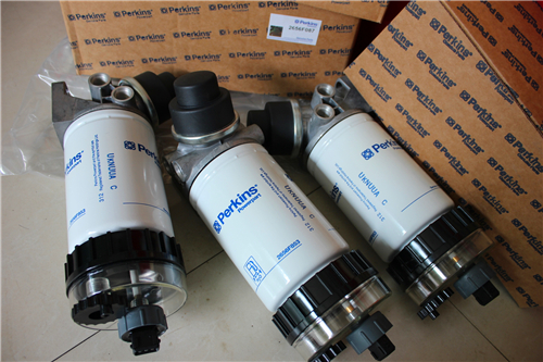
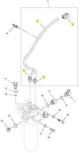
Perkins珀金斯1506A柴油发动机4587259燃油过滤器
详细描述
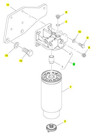
项目 零配件号码 新件号 描述
1 4587259 1 4587259 燃油过滤器
1 1 燃油过滤器
1 T416233 1 T416233 燃油过滤器
2 T400905 1 T400905 排泄栓塞
3 T400663 1 T400663 燃油过滤器座
6 CH10286 5 CH10286 栓塞
7 CH11880 5 CH11880 密封O型圈
8 T400667 1 T400667 栓塞
9 T405199 4 T405199 螺旋
10 T405615 4 T405615 垫圈
11 T400661 1 T400661 板
12 T400662 2 T400662 螺拴
13 29990022 2 29990022 垫圈
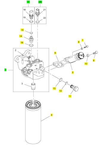
项目 零配件号码 新件号 描述
1 T400683 1 T400683 燃油过滤器座
4 4587258 1 4587258 燃油过滤器
4 T400688 1 T400688 燃油过滤器
5 CH10439 1 CH10439 汽酒共腾泵
6 CH10008 1 CH10008 密封垫片
7 CH10246 1 CH10246 螺拴
8 CH10303 1 CH10303 垫圈
9 CH12447 1 CH12447 螺拴
10 CH10277 1 CH10277 垫圈
11 CH10836 1 CH10836 阀
12 T400684 1 T400684 密封O型圈
13 T400188 1 T400188 密封O型圈
14 T400689 1 T400689 承接器
15 T409314 1 T409314 密封O型圈
16 T406205 1 T406205 密封O型圈
17 KRP1699 1 KRP1699 油压感应传感器装备
20 KRP1687 1 KRP1687 温度感应传感器
项目 零配件号码 新件号 描述
1 T400690 1 T400690 线束
6 CH10054 1 CH10054 缆拉杆
7 T400693 2 T400693 承接器
8 T406205 2 T406205 密封O型圈
9 T400692 1 T400692 承接器
10 T406205 1 T406205 密封O型圈
11 T400694 1 T400694 栓塞
12 T400695 1 T400695 密封O型圈
13 T400857 1 T400857 密封O型圈
14 T400428 2 T400428 栓塞
15 T406205 2 T406205 密封O型圈
16 CH12665 1 CH12665 螺拴
17 CH11819 1 CH11819 垫圈
18 CH12612 1 CH12612 螺拴
19 CH11819 1 CH11819 垫圈
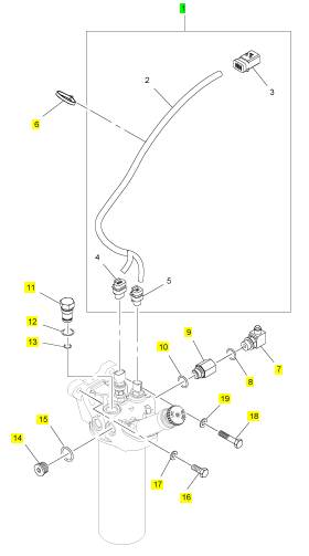
项目 零配件号码 新件号 描述
2 1 线束
3 T400691 1 T400691 电力连接器
4 28170029 1 28170029 电力连接器
5 28170044 1 28170044 电力连接器
|
To dismantle |
|
Operation 11-6 |
|
1 Clean the outside surfaces of the fuel lift pump. |
|
2 Remove the lift pump from the high-pressure pump, see Operation 11-5. 3 Remove the push rod (A12). |
|
4 Remove the end nut (A10). |
|
5 Remove and discard the ’O’ ring (A9) from the end nut. 6 Remove and discard the small ’O’ ring (A11) from inside the end nut. |
|
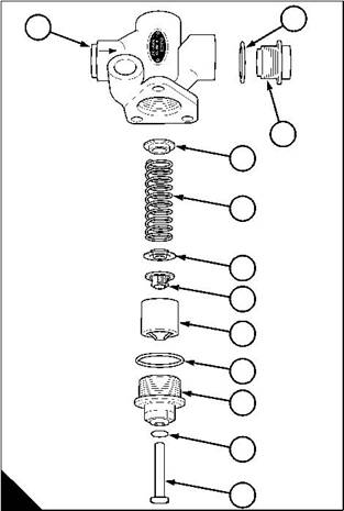
7 Remove the plunger (A8) the suction valve (A7) the spring seat washer (A6) the spring (A5) and the second spring seat washer (A4) from the pump body (A1). |
|
8 Remove the delivery valve assembly (A3) from the body. |
|
9 Remove and discard the ’O’ ring (A2) from the delivery valve assembly. |
|
2 |
|
1 |
|
3 |
|
4 |
|
5 |
|
6 7 |
|
8 |
|
9 |
|
10 |
|
11 |
|
A |
|
12 |
|
W067 |
|
174 |
|
Workshop Manual, TPD 1353E, Issue 3 |
|
This document has been printed from SPI². Not for Resale |
![]()
![]()
![]()
![]()

![]()
|
11 |
|
Peregrine EDi and 1300 Series EDi To assemble |
|
Operation 11-7 |
|
1 Thoroughly clean inside the body of the lift pump and ensure that the passages in the body are not restricted. |
|
2 Carefully clean the valves in clean diesel fuel. Inspect each valve for damage to the valve spring and the valve plate. If there is damage, renew the valve. |
|
3 Fit a spring seat washer (A4) in position in the pump body (A1). Ensure that the flat face of the washer is toward the bottom of the body. |
|
4 Fit the spring (A5) on the spring seat washer (A4) and the other spring seat washer (A6) on the spring. |
|
5 Fit the suction valve (A7) in position on top of the valve seat washer. Ensure that the large diameter of the valve is toward the spring seat washer. |
|
6 Fit the plunger (A8) in position in the pump body over the valve and spring. |
|
7 Renew the ’O’ ring (A11) that fits inside the end nut (A10) and renew the ’O’ ring (A9) on the outside of the end nut. |
|
8 Support the pump body, put the end nut in position on the plunger. Compress the spring and engage the threads of the end nut with the threads in the pump body. Tighten the end nut to 42 Nm (31 lbf ft) 4,3 kgf m. |
|
9 Fit the push rod (A12) in position in the end nut. |
|
10 Fit a new ’O’ ring (A2) on the delivery valve assembly (A3). |
|
11 Fit the delivery valve assembly to the fuel delivery pump and tighten to 42 Nm (31 lbf ft) 4,3 kgf m. |
|
2 |
|
1 |
|
3 |
|
4 |
|
5 |
|
6 7 |
|
8 |
|
9 |
|
10 |
|
11 |
|
A |
|
12 |
|
W067 |
|
Workshop Manual, TPD 1353E, Issue 3 |
|
175 |
|
This document has been printed from SPI². Not for Resale |
![]()
![]()
![]()
![]()
![]()
|
11 |
|
Peregrine EDi and 1300 Series EDi |
|
To set the adjustment of the speed control |
|
Operation 11-8 |
|
Special equipment is necessary to set the idle speed and the maximum no load speed. If further information is required, contact the Service Department of Perkins Engines Company Limited at Peterborough. |
|
176 |
|
Workshop Manual, TPD 1353E, Issue 3 |
|
This document has been printed from SPI². Not for Resale |
![]()
![]()
![]()
![]()
|
11 |
|
Peregrine EDi and 1300 Series EDi To eliminate air from the fuel system |
|
Operation 11-9 |
|
If air enters the fuel system, it must be eliminated before the engine can be started. Air can enter the system if: |
|
l The fuel tank is drained during normal operation. |
|
l The low-pressure fuel pipes are disconnected. |
|
l A part of the low-pressure fuel system leaks during engine operation. In order to eliminate air from the fuel system, proceed as follows: |
|
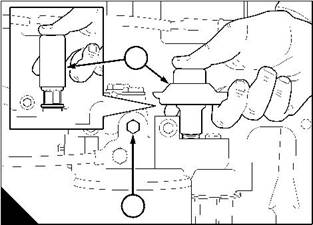
1 Loosen the vent plug (A1) on the top of the fuel filter head. |
|
2 Operate the plunger of the fuel priming pump (A2) until fuel, free from air, comes from the filter vent point. Tighten the vent plug. |
|
3 Turn the start key to the “ON” position. |
|
4 Operate the starter motor for intervals of 15 seconds until the engine starts. If the engine runs correctly for a short time and then stops or runs roughly, check for air in the fuel system. If there is air in the fuel system, there is probably a leak in the low pressure system. Turn the start key to the “OFF” position to stop the engine. Correct the leak and repeat the procedure. |
|
2 |
|
1 |
|
A |
|
W011/1 |
|
Workshop Manual, TPD 1353E, Issue 3 |
|
177 |
|
This document has been printed from SPI². Not for Resale |
![]()
![]()
![]()
![]()
|
This page is intentionally blank |
|
This document has been printed from SPI². Not for Resale |
|
Peregrine EDi and 1300 Series EDi |
|
12 |
|
Cooling system |
|
12 |
|
General description |
|
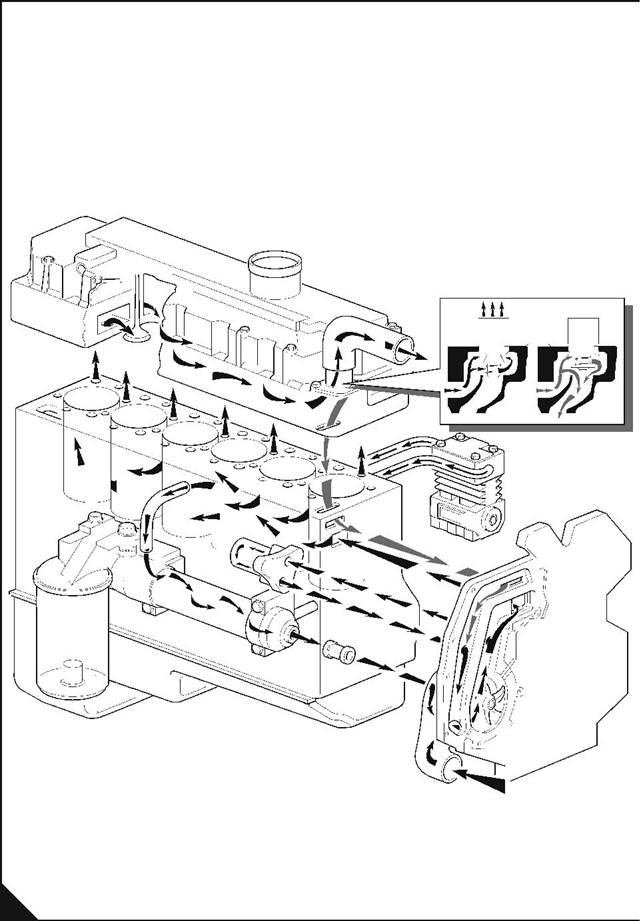
Coolant from the bottom of the radiator passes along a channel in the timing case to the centrifugal coolant pump, which is fitted on the front of the timing case. The pump is belt driven and assists the flow of the coolant through the system. The coolant passes along another channel in the timing case to a passage in the cylinder block. An equal amount of coolant passes to the bottom of each cylinder liner at an angle. This angle causes the coolant to move around and up the cylinder liners. The movement of the coolant helps to cool the cylinders. The coolant leaves the cylinder head at the front and passes into the thermostat housing. If the thermostat is closed, the coolant goes directly through a by-pass to the inlet side of the coolant pump; if the thermostat is open, the by-pass is closed and the coolant passes to the top of the radiator. |
|
From the cylinder block, coolant also passes through the oil cooler to the inlet side of the coolant pump. From the cylinder block, coolant also passes through the air compressor, if one is fitted. |
|
A coolant filter is fitted to the rear of the timing case. Ports in the coolant channels in the timing case allow 3% to 10% of the coolant to pass through the filter. The filter contains a special inhibitor that helps to prevent corrosion in the cooling system. |
|
A tensioner pulley automatically maintains the correct tension of the drive belt. |
|
Workshop Manual, TPD 1353E, Issue 3 |
|
179 |
|
This document has been printed from SPI². Not for Resale |
![]()
![]()
|
12 |
|
Peregrine EDi and 1300 Series EDi |
|
Cooling system flow diagram |
|
A |
|
PW137 |
|
180 |
|
Workshop Manual, TPD 1353E, Issue 3 |
|
This document has been printed from SPI². Not for Resale |
![]()
![]()
|
12 |
|
Peregrine EDi and 1300 Series EDi |
|
Coolant filter |
|
To renew the canister of the coolant filter / inhibitor |
|
Operation 12-1 |
|
Warning! Do not remove the canister while the engine is still hot and under pressure because dangerous hot fluid can be discharged. |
|
Caution: The canister contains a corrosion inhibitor that is circulated around the cooling system as the coolant passes through the canister. It is important that only the genuine correct Perkins canister is used. |
|
1 When the engine has cooled, remove the radiator filler cap to release the system pressure. |
|
Notes: |
|
l Up to engine number N117199, when the system pressure is released, automatic check valves in the filter head will close to prevent the loss of coolant when the filter canister is removed. |
|
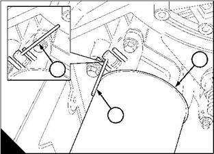
l From engine number N117199, a manual valve is fitted and is shown open (A2). When the system pressure is released, the valve lever must be turned counter-clockwise to the closed position (A1) to prevent the loss of coolant when the filter canister is removed. |
|
2 Thoroughly clean the outside surfaces of the coolant filter canister. |
|
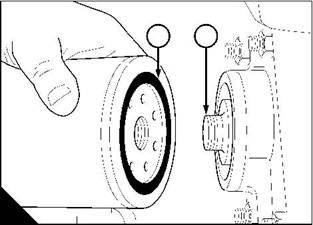
3 Use a strap wrench or similar tool to loosen the filter canister and remove the canister. 4 Ensure that the threaded adaptor (B2) is secure in the filter head and that the inside of the head is clean. |
|
5 Lubricate lightly the seal (B1) on top of the new filter canister with clean engine coolant. Fit the new canister to the filter head and tighten by hand. Do not overtighten the canister. |
|
6 Turn the lever (A2) 90° clockwise to open the valve. This will allow the flow of coolant through the canister. |
|
1 |
|
2 |
|
3 |
|
1 |
|
2 |
|
A |
|
B |
|
W1170 |
|
W007 |
|
Workshop Manual, TPD 1353E, Issue 3 |
|
181 |
|
This document has been printed from SPI². Not for Resale |
![]()
![]()
![]()
![]()
![]()
|
12 |
|
Peregrine EDi and 1300 Series EDi |
|
Thermostat |
|
To remove and to fit |
|
Operation 12-2 |
|
,
To remove |
|
1 Drain the cooling system so that the coolant level is below the thermostat position and disconnect the top hose from the water outlet connection. |
|
2 Release the setscrews and remove the thermostat assembly (A). Discard the ’O’ ring (A1). To fit |
|
1 Ensure that the joint faces of the thermostat assembly and the outlet are clean. |
|
2 Fit a new ’O’ ring to the thermostat assembly and insert the thermostat assembly in position on the cylinder head. Fit and tighten the setscrews. |
|
3 Connect the top hose and fill the cooling system. |
|
1 |
|
A |
|
W104 |
|
To test |
|
Operation 12-3 |
|
1 Hang the thermostat in a suitable container filled with water. |
|
2 Heat the water gradually. Use a thermometer to check the temperature at which the valve starts to open and at which it is fully open. The correct temperatures are given in the relevant Data and dimensions for the "Thermostat" on page 18. |
|
182 |
|
Workshop Manual, TPD 1353E, Issue 3 |
|
This document has been printed from SPI². Not for Resale |