English
 Espaol
 Franais
 阿拉伯
阿拉伯 中文
中文 Deutsch
 Italiano
 Português
 日本
日本 韩国
韩国 български
 hrvatski
 esky
esky Dansk
Dansk Nederlands
 suomi
suomi Ελληνικ
 印度
印度 norsk
norsk Polski
 Roman
Roman русский
 Svenska
Perkins珀金斯1506A柴油发动机CH11087交流充电发电机供应商,Perkins珀金斯1506A柴油发动机CH11087交流充电发电机技术价格规格咨询服务,Perkins珀金斯1506A柴油发动机CH11087交流充电发电机零配件供应,Perkins珀金斯1506A柴油发动机CH11087交流充电发电机售后服务中心,Perkins珀金斯1506A柴油发动机CH11087交流充电发电机,Perkins珀金斯1506A柴油发动机CH11087交流充电发电机详细的技术参数,

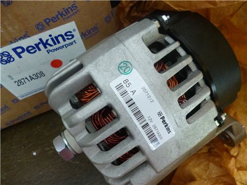
Perkins珀金斯1506A柴油发动机CH11087交流充电发电机
详细描述
项目 零配件号码 新件号 描述
1 CH11087 1 CH11087 交流充电发电机
(1) CH11087 1 CH11087 交换交流充电发电机

项目 零配件号码 新件号 描述
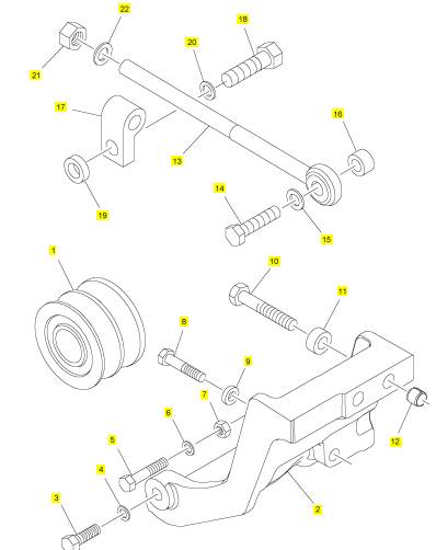
1 T400904 1 T400904 交流充电发电机皮带轮
2 T400676 1 T400676 交流充电发电机托架
3 T400672 1 T400672 螺拴
4 CH11604 1 CH11604 垫圈
5 T400673 1 T400673 螺拴
6 CH11604 2 CH11604 垫圈
7 2238155 1 2238155 螺帽
8 CH12124 1 CH12124 螺拴
9 T400675 1 T400675 间隔器
10 ST43558 2 ST43558I 螺拴
11 T400674 2 T400674 套筒
12 T400681 2 T400681 套筒
13 T401872 1 T401872 杆
13 T400678 1 T400678 杆
14 T406503 1 T406503 螺拴
15 CH10099 1 CH10099 垫圈
16 T400677 1 T400677 间隔器
17 T400679 1 T400679 间隔器
18 T400671 1 T400671 螺拴
19 T400680 1 T400680 间隔器
20 CH11604 1 CH11604 垫圈
21 T400670 2 T400670 螺帽
22 CH10099 2 CH10099 垫圈
项目 零配件号码 新件号 描述
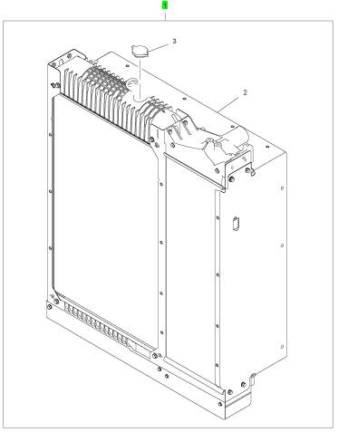
1 T401007 1 T401007 散热器
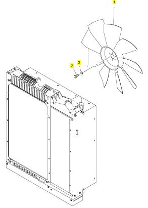
项目 零配件号码 新件号 描述
1 T400970 1 T400970 风扇
2 CH11895 6 CH11895 螺拴
3 CH10255 6 CH10255 垫圈
|
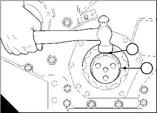
7 Use a hammer to carefully fit the key (D1) into its recess in the crankshaft nose (D2). Do not damage the key. |
|
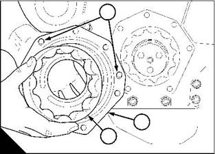
8 Lightly lubricate the outer rotor (E3) with clean engine lubricating oil. Fit the outer rotor into the pump body (E2). |
|
1 |
|
1 |
|
2 |
|
2 |
|
3 |
|
D |
|
E |
|
W120 |
|
W118 |
|
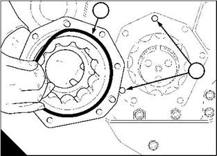
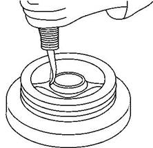
9 Fit a new ’O’ ring (F1) into its recess in the pump body. |
|
10 WK, WL, WP, and WQ (7,6 litre) engines, lubricate the main lip of the front oil seal with clean engine lubricating oil. WM, WN, WR, and WS (8,7 litre) engines, do NOT lubricate the seal. |
|
Caution: Lubrication of the front seal used on WM, WN, WR, and WS (8,7 litre) engines may reduce the life of the seal and affect its performance. Seals are not interchangeable between 7,6 litre and 8,7 litre engines due to seal thickness and material. |
|
11 Fit the pump body, ensure that the outer rotor is in mesh with the inner rotor. Ensure that the dowel pins (E1) in the oil pump body engage with the holes (F2) in the timing case cover. |
|
Caution: Fit a short setscrew at the 2 o-clock and the 3 o-clock positions. |
|
12 Fit the remainder of the setscrews, and tighten all the setscrews. |
|
13 Fit the crankshaft pulley / damper assembly, see Operation 5-2. |
|
14 Fill the sump to the correct level with an approved lubricating oil, see Chapter 5 in the User’s Handbook. |
|
1 |
|
2 |
|
F |
|
W119 |
|
142 |
|
Workshop Manual, TPD 1353E, Issue 3 |
|
This document has been printed from SPI². Not for Resale |
![]()
![]()
|
10 |
|
Peregrine EDi and 1300 Series EDi To inspect |
|
Operation 10-14 |
|
1 Remove the lubricating oil pump, see Operation 10-12. 2 Clean all the components of the oil pump. |
|
3 Visually inspect the components for damage and wear. If either the inner rotor or the outer rotor are damaged or worn they must both be renewed as an assembly. |
|
4 Put the outer rotor and the inner rotor into the pump body. |
|
5 Check the outer rotor to body clearance (A). Refer to the relevant Data and dimensions for the "Lubricating oil pump" on page 17. |
|
6 Check the inner rotor end-float (B). Refer to the relevant Data and dimensions for the "Lubricating oil pump" on page 17. |
|
7 Fit the lubricating oil pump, see Operation 10-13. |
|
A |
|
B |
|
W065 |
|
W064 |
|
Workshop Manual, TPD 1353E, Issue 3 |
|
143 |
|
This document has been printed from SPI². Not for Resale |
![]()
![]()
![]()
![]()
|
10 |
|
Peregrine EDi and 1300 Series EDi |
|
Front oil seal |
|
To renew (oil pump removed) |
|
Operation 10-15 |
|
Special requirements |
|
Special tools Description |
|
Consumable products |
|
Part number |
|
Description |
|
Part number |
|
Front oil seal installer adaptor |
|
21825953 |
|
POWERPART Compound |
|
1861147 |
|
Note: The front oil seal is fitted into the front of the oil pump housing. 1 Remove the pulley / damper assembly, see Operation 5-1. |
|
Notes: |
|
l The ‘positive on-shaft excluder’ (POSE) is not fitted on WK, WL, WP, and WQ engines. l Do not separate the wear sleeve from the POSE excluder. |
|
2 Using a suitable hand tool, remove the wear sleeve and also the POSE, if fitted, from the pulley / damper assembly (A). |
|
Caution: Care must be taken not to damage the pulley flange. |
|
3 Remove the oil seal from the pump with a suitable lever behind the main lip of the oil seal. Do not damage the edge of the oil pump housing or the crankshaft nose. |
|
4 Remove the lubricating oil pump, see Operation 10-12. |
|
A |
|
W1384 |
|
Continued |
|
144 |
|
Workshop Manual, TPD 1353E, Issue 3 |
|
This document has been printed from SPI². Not for Resale |
![]()
![]()
![]()
![]()
![]()

|
10 |
|
Peregrine EDi and 1300 Series EDi |
|
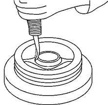
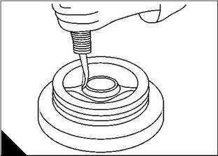
5 Fit a new oil seal onto tool 21825953 (B2) and align to the oil pump housing (B3). Apply POWERPART Compound to the outside diameter of the oil seal. |
|
6 Press (B1) the new oil seal into the oil pump housing (B3) until the seal is level with the front of the housing. Remove excess compound from the housing / seal. |
|
7 Apply POWERPART Compound to the inside diameter of the wear sleeve, and using the same press, fit the new wear sleeve together with the POSE seal onto the pulley / damper assembly. Remove excess compound. |
|
Caution: The wear sleeve is to be fitted so that the chamfer on the sleeve faces out when viewed from the rear of the pulley. |
|
8 Fit the lubricating oil pump to the engine, see Operation 10-13. |
|
9 Fit the pulley / damper assembly, see Operation 5-2. |
|
10 Fill the sump to the correct level with an approved lubricating oil, see Chapter 5 in the User’s Handbook. |
|
1 |
|
2 |
|
3 |
|
B |
|
W263 |
|
Workshop Manual, TPD 1353E, Issue 3 |
|
145 |
|
This document has been printed from SPI². Not for Resale |
![]()
![]()
|
10 |
|
Peregrine EDi and 1300 Series EDi |
|
To renew (oil pump fitted) |
|
Operation 10-16 |
|
Special requirements |
|
Special tools Description |
|
Consumable products |
|
Part number |
|
Description |
|
Part number |
|
Crankshaft front oil seal replacer |
|
21825577 |
|
POWERPART Compound |
|
1861147 |
|
1 Remove the pulley / damper assembly, see Operation 5-1. |
|
Notes: |
|
l The ‘positive on-shaft excluder’ (POSE) is not fitted on WK, WL, WP, and WQ engines. l Do not separate the wear sleeve from the POSE excluder. |
|
2 Use a suitable hand tool, e.g. a chisel in an air hammer, to remove the wear sleeve, and the POSE, if fitted, from the pulley / damper assembly (A). |
|
Caution: Care must be taken not to damage the pulley flange. |
|
3 Remove the oil seal from the pump with a suitable lever behind the main lip of the oil seal. Do not damage the edge of the oil pump housing or the crankshaft nose. |
|
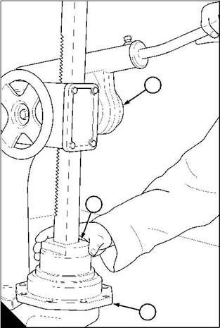
4 Fit adaptor (B1) of the installer to the crankshaft nose with three locally obtained hexagon head M12 x 1,25 x 40 long setscrews (B2), the heads must be small enough not to obstruct the thread of the replacer tool (B5). |
|
5 Fit a new oil seal (B3) onto tool 21825953 (B4) and align to the oil pump housing. Apply POWERPART Compound to the outer surface of the oil seal. |
|
6 Fit the replacer tool (B5) through the installer (B4) and fully engage the thread of the adaptor (B1). Tighten the nut of the replacer tool (B5) to push the oil seal (B3) into the pump housing until the seal is aligned with the front of the housing. |
|
7 Remove the replacer tool (B5), the installer tool (B4), the three setscrews (B2), and the adaptor (B1). Remove excess compound from the housing / seal. |
|
3 |
|
1 |
|
5 |
|
4 |
|
2 |
|
A |
|
B |
|
W1384 |
|
W1379 |
|
Continued |
|
146 |
|
Workshop Manual, TPD 1353E, Issue 3 |
|
This document has been printed from SPI². Not for Resale |
![]()
![]()
![]()
![]()
![]()

|
10 |
|
Peregrine EDi and 1300 Series EDi |
|
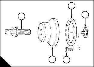
8 Fit the new wear sleeve complete with POSE to the damper in the direction of the arrow (C). Ensure that the chamfer on the wear sleeve’s outer diameter is facing out when viewed from the rear end of the damper. |
|
Caution: The new wear sleeve complete with the POSE must be fitted as a unit, do not separate them. |
|
9 WK, WL, WP, and WQ (7,6 litre) engines: lubricate the main lip of the front oil seal with clean engine lubricating oil. WM, WN, WR, and WS (8,7 litre) engines: do NOT lubricate the seal. |
|
Caution: Lubrication of the front seal used on WM, WN, WR, and WS (8,7 litre) engines may reduce the life of the seal and affect its performance. Seals are not interchangeable between 7,6 litre and 8,7 litre engines due to seal thickness and material. |
|
10 Fit the pulley and damper assembly, see Operation 5-2. |
|
11 Fit the fan drive belt, see Operation 12-7. |
|
12 Fill the sump to the correct level with an approved lubricating oil, see Chapter 5 in the User’s Handbook. |
|
C |
|
W1380 |
|
Workshop Manual, TPD 1353E, Issue 3 |
|
147 |
|
This document has been printed from SPI². Not for Resale |
![]()
![]()

|
10 |
|
Peregrine EDi and 1300 Series EDi |
|
Pressure relief valve |
|
To remove and to fit |
|
Operation 10-17 |
|
To remove |
|
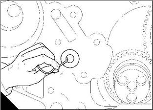
2 Note: The pressure relief valve operates at 550 kPa (80 lbf/in ) and is fitted into the crankcase, inside the timing case. |
|
1 Remove the timing case cover, see Operation 6-1. |
|
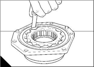
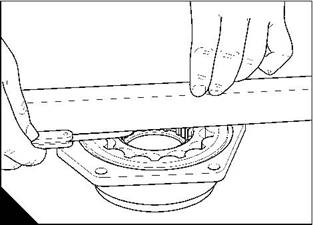
2 Push the pressure relief valve open and insert a piece of copper wire into the valve. Use the copper wire to pull the valve from the crankcase (A). |
|
To fit |
|
1 Clean the joint faces of the timing case cover. 2 Fit the pressure relief valve into position in the crankcase. 3 Fit the timing case cover, see Operation 6-2. |
|
A |
|
W141 |
|
To inspect |
|
Operation 10-18 |
|
1 Remove the pressure relief valve, see Operation 10-17. 2 Visually inspect the valve assembly for damage. |
|
Caution: If the pressure relief valve is damaged, then it must be renewed. |
|
3 Fit a new pressure relief valve into position in the crankcase, see Operation 10-17. |
|
148 |
|
Workshop Manual, TPD 1353E, Issue 3 |
|
This document has been printed from SPI². Not for Resale |
![]()
![]()
![]()
![]()
![]()
![]()
|
10 |
|
Peregrine EDi and 1300 Series EDi |
|
Breather system |
|
To clean |
|
Operation 10-19 |
|
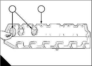
The engines have open breather systems. Breather elements are fitted inside the rocker cover assembly. The breather elements (A1) separate lubricating oil from the crankcase gases. The oil is kept inside the rocker cover (A2) and the crankcase gases pass through the breather element into an open breather pipe. |
|
To renew the breather elements, see Operation 3-3. Warning! Do not direct compressed air at your skin. 1 Remove the rocker cover, see Operation 3-1. |
|
2 Remove the breather elements from the rocker cover (A2). Wash the breather element (A1) and the breather pipe with an approved cleaning fluid and dry it with low pressure air. |
|
3 Clean the rocker cover with an approved cleaning fluid and dry it with low pressure air. 4 Fit the rocker cover, see Operation 3-2. |
|
1 |
|
2 |
|
A |
|
W200/2 |
|
Workshop Manual, TPD 1353E, Issue 3 |
|
149 |
|
This document has been printed from SPI². Not for Resale |
![]()
![]()
![]()
![]()
|
10 |
|
Peregrine EDi and 1300 Series EDi |
|
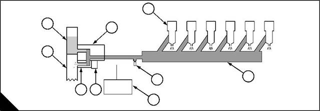
General description (High-pressure system) |
|
Lubricating oil from the main pressure rail passes into a channel in the timing case, then into the reservoir (A1) for the high-pressure pump (A2). |
|
The lubricating oil passes from the pump, under high-pressure, to a regulator valve (A8). |
|
l Some oil is discharged into the timing case (A9), by the valve. |
|
l Some oil is sent to the supply manifold (A4), then to the injector units (A3). |
|
The high-pressure lubrication system provides the pressure to actuate the fuel injector units. The value of the oil pressure can be altered by the engine management system, this pressure is known as “injection control pressure”. |
|
Three components work in a cycle to alter the injection control pressure: |
|
1 A sensor (A5) in the supply manifold, sends a signal to the engine control module (A6). |
|
2 The engine control module, uses the signal from the sensor to check the oil pressure. If the pressure needs to be altered, the module sends a signal to the solenoid (A7) of the regulator valve (A8). |
|
3 The regulator valve, changes the injection control pressure. |
|
Any change of injection control pressure, will affect the sensor, and the cycle will start again. |
|
3 |
|
1 |
|
2 |
|
9 |
|
4 |
|
5 |
|
8 |
|
7 |
|
6 |
|
A |
|
W244 |
|
Continued |
|
150 |
|
Workshop Manual, TPD 1353E, Issue 3 |
|
This document has been printed from SPI². Not for Resale |
![]()
![]()