 English
 Espaol
 Franais
 阿拉伯
阿拉伯 中文
中文 Deutsch
 Italiano
 Português
 日本
日本 韩国
韩国 български
 hrvatski
 esky
esky Dansk
Dansk Nederlands
 suomi
suomi Ελληνικ
 印度
印度 norsk
norsk Polski
 Roman
Roman русский
 Svenska
Perkins珀金斯1306-E87TA86柴油发动机传感器供应商,Perkins珀金斯1306-E87TA86柴油发动机传感器技术价格规格咨询服务,Perkins珀金斯1306-E87TA86柴油发动机传感器零配件供应,Perkins珀金斯1306-E87TA86柴油发动机传感器售后服务中心,Perkins珀金斯1306-E87TA86柴油发动机传感器,Perkins珀金斯1306-E87TA86柴油发动机传感器详细的技术参数,

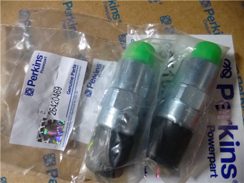
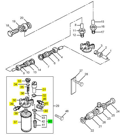
Perkins珀金斯1306-E87TA86柴油发动机传感器
详细描述
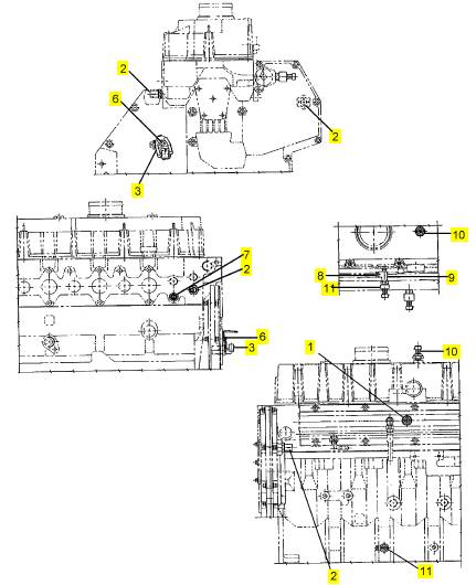
项目 零配件号码 新件号 描述
1 1830669 C91 1 1830669 C92 感应传感器 ICP 感应传感器
2 1814320 C1 2 检查历史 感应传感器 EOT& ECT 感应传感器
3 1807339 C94 1 1885812 C91 感应传感器
3 1807339 C92 1 1885812 C91 转换器 CMP 感应传感器
3 1807339 C93 1 1885812 C91 感应传感器
6 1817812 C1 1 1817812 C1 公制的螺拴
7 445751 2 445751 栓塞
8 444613 4 444613 栓塞
9 1 TEEPIECE
10 1840078 C1 1 1840078 C1 转换器
10 1813658 C2 1 1840078 C1 转换器 地图感应传感器
11 1807369 C2 1 1807369 C2 油压感应传感器 EOP 感应传感器
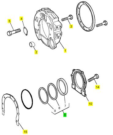
项目 零配件号码 新件号 描述
1 1820338 C1 1 1820338 C2 飞轮壳
2 1822086 C1 2 1822086 C1 合钉
3 1820606 C1 8 1820606 C1 公制的螺拴
4 686702 C1 1 686702 C2 板
5 1817953 C1 2 1817953 C1 公制的螺拴
6 1817867 C92 1 1817867 C93 密封 -后油封
10 1841139 C93 1 1841139 C93 密封 - 再操作系统壳
10 1815699 C2 1 1841139 C93 壳
10 1815699 C3 1 1841139 C93 台车
14 1817958 C1 6 1817958 C1 螺旋
15 1824911 C1 1 1841974 C1 密封垫片 - 飞轮壳
项目 零配件号码 新件号 描述
1 1825520 C91 1 1825520 C91 管 -燃油
6 1825467 C1 1 1825467 C1 连接
7 691273 C1 1 691273 C1 密封垫片
8 1825521 C93 1 1825521 C93 管 -燃油
13 1825467 C1 1 1825467 C1 连接
14 691273 C1 1 691273 C1 密封垫片
15 1829801 C91 1 1829801 C91 管 -燃油 1026910
15 1825522 C92 1 1825522 C92 燃油管 1026909
18 1810491 C1 1 1810491 C1 螺旋
19 691273 C1 1 691273 C1 密封垫片
20 691273 C1 1 691273 C1 密封垫片
21 1825511 C1 1 1825511 C1 非回路阀
22 397630 C1 1 检查历史 密封垫片
23 1809797 C1 1 1809797 C1 连接
24 1810491 C1 1 1810491 C1 螺旋
25 691273 C1 1 691273 C1 密封垫片
26 691273 C1 1 691273 C1 密封垫片
27 1823920 C1 1 1823920 C1 夹
28 1817956 C1 1 1817956 C1 公制的螺拴
29 1825661 C93 1 1825661 C94 燃油过滤器组合
48 1817978 C1 2 1817978 C1 螺拴
49 1819772 C1 1 1819772 C1 承接器
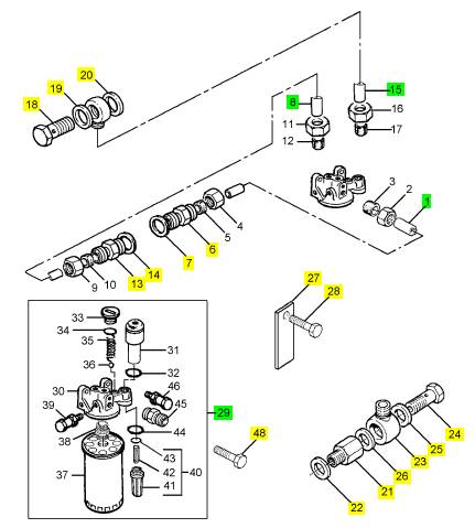
项目 零配件号码 新件号 描述
30 1 过滤器座
31 1824946 C1 1 1825473 C93 汽酒共腾泵
32 1823029 C1 1 1823029 C1 密封垫片
33 1820919 C1 1 1820919 C1 栓塞
34 379181 R1 1 379181 R1 密封O型圈
35 1823734 C1 1 1823734 C1 弹簧
36 1820478 C1 1 1820478 C1 球
37 26560137 1 26560137 燃油过滤器
38 1 承接器
39 1822530 C92 1 1822530 C92 阀
40 1817677 C91 1 1817677 C91 过滤器
44 1823782 C1 1 1823782 C1 密封O型圈
45 606819 C1 3 606819 C1 连接
46 39677 DA 1 1816216 C1 铸漏件
47 1816216 C1 1 1816216 C1 铸漏件
|
Special requirements |
|
Special tools Part number |
|
Description Remover / replacer for valve guides Adaptor |
|
Description |
|
Part number |
|
21825478 21825479 |
|
Adaptor |
|
21825935 |
|
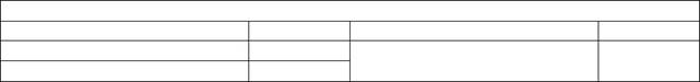
1 Clean the parent bore for the valve guide (A6). 2 Lubricate the outer surface of the new guide with clean engine lubricating oil. |
|
3 Fit the adaptor 21825479 (A5) into the remover / replacer tool 21825478 (A3). Pass the tool and adapter through the spacer (A4) and the cylinder head, from the bottom face. Fully fasten the valve guide, with the large 15° chamfer at the bottom, and the distance piece (A7), 21825935, onto the adapter with the attachment (A8). |
|
4 Turn the top handle (A1) to take up the excess movement in the tool and turn the bottom handle (A2) to pull the valve guide into the cylinder head. |
|
Caution: Do not ream new valve guides. They are supplied in a finished condition. |
|
1 |
|
2 |
|
3 |
|
4 5 |
|
6 7 8 |
|
A |
|
W133 |
|
40 |
|
Workshop Manual, TPD 1353E, Issue 3 |
|
This document has been printed from SPI². Not for Resale |
![]()
![]()
![]()
![]()
|
3 |
|
Peregrine EDi and 1300 Series EDi |
|
Cylinder head |
|
To inspect and to correct |
|
Operation 3-17 |
|
1 Remove the cylinder head assembly, see Operation 3-8. 2 Remove the valve springs and the valves, see Operation 3-10. 3 Remove the thermostat, see Operation 12-2. |
|
4 Inspect the cylinder head for signs of gas or coolant leakage. |
|
5 Clean the face of the cylinder head, the passages for coolant and the passages for the lubricating oil. |
|
6 The water jacket can be cleaned with a special solvent, which must be used in accordance with the manufacturer’s instructions. |
|
2 |
|
2 |
|
7 Pressure test the cylinder head to a pressure of 124/138 kPa (18/20 lbf in ) 1,27/1,41 kgf cm and inspect |
|
the cylinder head for leaks. |
|
Warning! Always use a safety cage to protect the operator when a component is to be pressure tested in a bath of water. Fit safety wires to secure the plugs that seal the hose connections of a component that is to be pressure tested. |
|
8 When the cylinder head is thoroughly clean, check it for cracks. Examine carefully the areas around the valve seats and around the holes for the injector units. |
|
9 The bottom face of the cylinder head can be machined if: l There is distortion (see step 10). |
|
l There are deep scratches. |
|
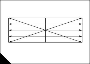
10 Use a straight edge and feeler gauges to check the cylinder head for distortion (A) across and along its bottom face, refer to the relevant Data and dimensions for the "Cylinder head" on page 10. If the distortion is more than the given limit the bottom face can be machined. |
|
Cautions: |
|
l Remove only the minimum material and ensure that the thickness of the cylinder head will not be less than 106,17 mm (4.180 in) after the cylinder head has been machined. |
|
l After the cylinder head has been machined the valve seats must be corrected to give the correct valve head depth, see Operation 3-18. |
|
l It is advisable to work to the minimum limit to allow for later wear. |
|
1 |
|
2 |
|
2 |
|
3 4 5 |
|
3 4 5 |
|
6 |
|
6 |
|
1 |
|
A |
|
W026 |
|
Continued |
|
Workshop Manual, TPD 1353E, Issue 3 |
|
41 |
|
This document has been printed from SPI². Not for Resale |
![]()
![]()
![]()
![]()
![]()
|
3 |
|
Peregrine EDi and 1300 Series EDi |
|
11 Check the valve seats for wear and for damage. |
|
12 Before any work is done on the valve seats, new valve guides must be fitted, see Operation 3-15 and Operation 3-16. |
|
13 Where there is little damage, the valve and valve seat can be lapped. When the valve seats are lapped keep the seat to the measurements given in the relevant Data and dimensions for the "Cylinder head" on page 10. Ensure that all the compound used to lap the valve seat is removed from the valve and the valve seat. |
|
14 Badly damaged valve seats can be corrected with a valve seat cutter, see Operation 3-18. |
|
42 |
|
Workshop Manual, TPD 1353E, Issue 3 |
|
This document has been printed from SPI². Not for Resale |
![]()
![]()
|
3 |
|
Peregrine EDi and 1300 Series EDi |
|
To |
|
To correct a valve seat with a valve seat cutter |
|
Operation 3-18 |
|
Special requirements Special tools |
|
Description |
|
Part number |
|
Set of adjustable cutters for valve seats |
|
21825938 |
|
1 Before work is done on the valve seats, new valve guides must be fitted. 2 Fit the pilot in the valve guide and tighten the pilot. |
|
3 Select the relevant cutter. Set the blades of the cutters to the diameter of the valve seat to be cut. Fit the cutter on the pilot and fit the handle. Ensure that the cutter is not allowed to fall on to the seat as this can damage the blades. |
|
4 Carefully rotate the cutter in a clockwise direction (A). Remove only the minimum material to ensure a good seat. Keep the seat as narrow as possible. |
|
5 When the seat is cut, remove the cutter and the pilot. Remove any debris from the area of the valve seat and the port. |
|
6 Fit the valve and lightly lap the valve and the seat. |
|
7 Check that the valve depth is within limits, see Operation 3-12. |
|
8 If a valve seat has become too damaged or too worn to correct, a new valve seat insert can be fitted, see Operation 3-19. |
|
A |
|
W134 |
|
Workshop Manual, TPD 1353E, Issue 3 |
|
43 |
|
This document has been printed from SPI². Not for Resale |
![]()
![]()
![]()
![]()
|
3 |
|
Peregrine EDi and 1300 Series EDi |
|
To fit valve seat inserts |
|
Operation 3-19 |
|
1 Fit new valve guides, see Operation 3-15 and Operation 3-16. |
|
2 With the bore of the new valve guide used as a pilot, machine out the old insert. Remove all debris and clean the insert recess. |
|
3 If the bottom face of the cylinder head has been machined, the insert will have to be surface ground on the back face to ensure that there is no protrusion of the insert above the bottom face of the cylinder head. After the back of the insert has been ground, ensure that the outer edge of the back face has a 0,9/1,3 mm (0.035/ 0.051 in) chamfer at 30° to the vertical. |
|
Warning! When frozen components are handled, frost proof gloves must be worn. If liquid nitrogen is used to freeze components, then eye protection must also be worn. |
|
4 Put the valve seat inserts in a deep freeze unit for 30 minutes. This will reduce the size of the valve seat inserts to allow them to fit more easily into their recesses. |
|
5 With the bore of the valve guide used as a pilot, and with the rear face of the insert towards the cylinder head, press in the insert (A). Use a hydraulic press or a hand press in one continuous movement. Do not use a hammer on the insert and do not use lubrication. Ensure that the bottom of the insert is in contact with the bottom of the recess. |
|
6 Cut the valve seat at an included angle of 90° for 45° valve seats or 120° for 30° valve seats, see Operation 3-18. Lap the valve on to the valve seat. Ensure that the depth of the valve head below the face of the cylinder head is within the production limits, see Operation 3-12. |
|
Note: Work as near as possible to the minimum figure to allow for future wear on the valve seat. |
|
A |
|
W115 |
|
44 |
|
Workshop Manual, TPD 1353E, Issue 3 |
|
This document has been printed from SPI². Not for Resale |
![]()
![]()
![]()
![]()
|
3 |
|
Peregrine EDi and 1300 Series EDi |
|
To renew injector unit sleeves |
|
Operation 3-20 |
|
Special requirements |
|
Special tools Part number |
|
Description |
|
Description |
|
Part number 27610093 |
|
Special tap |
|
27610091 21825960 27610092 |
|
Adaptor (for use with 21825960 and 27610092) |
|
Injector unit sleeve remover Adaptor |
|
Tool to fit the injector unit sleeve |
|
27610094 |
|
Consumable products |
|
Description |
|
Part number |
|
21820119 or 21820120 |
|
POWERPART Stud and bearing lock |
|
To remove |
|
1 Remove the fuel injector units, see Operation 11-2. |
|
Caution: If the correct procedure is not used, the cylinders of the engine will be filled with fuel and engine lubricating oil. |
|
2 Put a suitable plug into the bottom of each sleeve to prevent the entry of debris into the cylinder. |
|
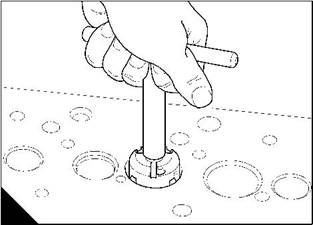
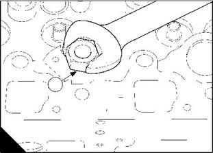
3 Put the special tap, 27610091, (A1) into the sleeve for the injector unit and cut a thread into the sleeve (A). Remove the tap. |
|
4 Fit and tighten the adaptor 27610092 (B1) into the injector unit sleeve. |
|
1 |
|
1 |
|
A |
|
B |
|
W214 |
|
W215 |
|
Continued |
|
Workshop Manual, TPD 1353E, Issue 3 |
|
45 |
|
This document has been printed from SPI². Not for Resale |
![]()
![]()
![]()
![]()

|
3 |
|
Peregrine EDi and 1300 Series EDi |
|
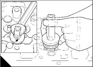
5 Fit the adaptor 27610093 (C2) into the adaptor 27610092 (C1). |
|
6 Fit the injector unit sleeve remover 21825960 (C3) (slide hammer) to the adaptor. |
|
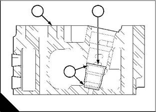
7 Operate the sleeve remover to free the injector unit sleeve (D2) from the contact surfaces (D3) in the cylinder head (D1). |
|
1 |
|
2 |
|
2 |
|
3 |
|
3 |
|
1 |
|
C |
|
D |
|
W1391 |
|
W1388 |
|
To fit |
|
Caution: Ensure that the piston is at the bottom of the cylinder or the tool used to fit the injector unit sleeve might hit the piston. Do not allow debris to fall into the cylinder. |
|
1 Use a wire brush to clean the top and bottom of the bore for the injector unit sleeve. 2 Remove any debris. |
|
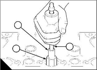
3 Put the sleeve onto the tool 27610094. Put POWERPART Stud and bearing lock onto the top and bottom contact faces (E1) of the injector unit sleeve. |
|
Note: Illustration (F) shows the contact faces (F3) of the injector unit sleeve (F2) in the cylinder head (F1). |
|
1 |
|
2 |
|
1 |
|
3 |
|
E |
|
F |
|
W1389 |
|
W1388 |
|
Continued |
|
46 |
|
Workshop Manual, TPD 1353E, Issue 3 |
|
This document has been printed from SPI². Not for Resale |
![]()
![]()

|
3 |
|
Peregrine EDi and 1300 Series EDi |
|
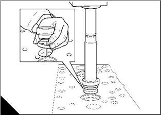
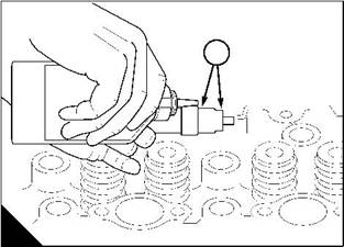
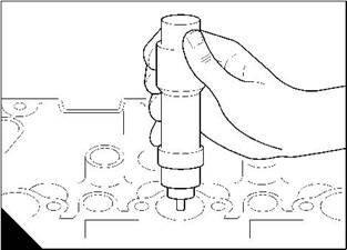
4 Put the sleeve and the tool into the bore for the injector unit in the cylinder head (G). |
|
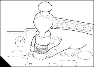
5 Hit the tool with a hammer to drive the injector unit sleeve into position at the bottom of the bore (H) in the cylinder head. |
|
6 Remove the tool. |
|
7 Fit the injector units, see Operation 11-3. |
|
G |
|
H |
|
W1390 |
|
W1387 |
|
Workshop Manual, TPD 1353E, Issue 3 |
|
47 |
|
This document has been printed from SPI². Not for Resale |
![]()
![]()
|
3 |
|
Peregrine EDi and 1300 Series EDi |
|
To set the valve tip clearance |
|
Operation 3-21 |
|
Notes: |
|
l The valve tip clearance is measured between the top of the valve stem and the rocker lever (B). |
|
l With the engine hot or cold, the correct clearances are 0,64 mm (0.025 in) for the inlet valves and for the exhaust valves. |
|
l The positions of the valves are shown at (A). Number 1 cylinder is at the front of the engine. l The arrangement of the valves for each cylinder, in sequence, is inlet valve then exhaust valve. |
|
Method one |
|
1 Remove the rocker cover, see Operation 3-1. |
|
2 Rotate the crankshaft in the normal direction of rotation until valve (A11) has just opened and valve (A12) has not closed fully. Check / adjust the clearances of valves (A1) and (A2). |
|
3 Set valves (A3) and (A4) as indicated above then check / adjust the clearances of valves (A9) and (A10). 4 Set valves (A7) and (A8) then check / adjust the clearances of valves (A5) and (A6). 5 Set valves (A1) and (A2) then check / adjust the clearances of valves (A11) and (A12). 6 Set valves (A9) and (A10) then check / adjust the clearances of valves (A3) and (A4). 7 Set valves (A5) and (A6) then check / adjust the clearances of valves (A7) and (A8). 8 Fit the rocker cover, see Operation 3-2. |
|
1 |
|
2 |
|
3 |
|
4 |
|
5 |
|
6 |
|
7 |
|
8 |
|
9 |
|
10 |
|
11 |
|
12 |
|
A |
|
W015 |
|
% |
|
48 |
|
Workshop Manual, TPD 1353E, Issue 3 |
|
This document has been printed from SPI². Not for Resale |