 English
 Espaol
 Franais
 阿拉伯
阿拉伯 中文
中文 Deutsch
 Italiano
 Português
 日本
日本 韩国
韩国 български
 hrvatski
 esky
esky Dansk
Dansk Nederlands
 suomi
suomi Ελληνικ
 印度
印度 norsk
norsk Polski
 Roman
Roman русский
 Svenska
Perkins珀金斯1306-E87TA86柴油发动机2593597 C91喷油器供应商,Perkins珀金斯1306-E87TA86柴油发动机2593597 C91喷油器技术价格规格咨询服务,Perkins珀金斯1306-E87TA86柴油发动机2593597 C91喷油器零配件供应,Perkins珀金斯1306-E87TA86柴油发动机2593597 C91喷油器售后服务中心,Perkins珀金斯1306-E87TA86柴油发动机2593597 C91喷油器,Perkins珀金斯1306-E87TA86柴油发动机2593597 C91喷油器详细的技术参数,


Perkins珀金斯1306-E87TA86柴油发动机2593597 C91喷油器
详细描述
项目 零配件号码 新件号 描述
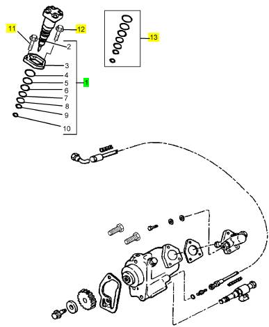
1 1830692 C92 6 2593597 C91 喷油器
11 1830050 C2 6 1830050 C2 螺拴
12 1830051 C2 6 1830051 C2 螺拴
13 1830742 C92 1 1830742 C92 密封装备
|
Peregrine EDi and 1300 Series EDi |
|
To dismantle and inspect |
|
Operation 3-6 |
|
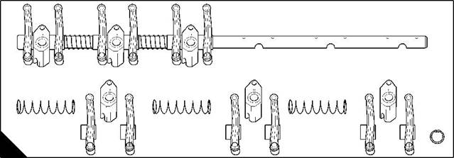
1 Remove the circlip from the end of the rocker shaft. |
|
2 Slide all of the components from the shaft and put them on a bench in the correct sequence. 3 Inspect all of the components for signs of damage. |
|
4 Check the rocker shaft, the rocker levers and the bushes for deep scratches or signs of excessive wear. |
|
5 The bushes of the rocker lever have a groove to assist with lubrication, ensure that the grooves are free from debris. |
|
6 Measure the internal diameter of the bushes at two places 90° apart and record the readings. |
|
7 Measure the external diameter of the rocker shaft at two places 90° apart where it contacts the bushes of the rocker levers. Record the readings. |
|
8 If the difference between the measurements is greater than 0,13mm (0.005 in), renew the worn component, either the shaft or the bushes. |
|
9 Ensure that all the lubricating oil holes and passages of the rocker shaft assembly are free of debris. 10 Check the plugs at the ends of the rocker shaft for leaks or damage. |
|
11 Measure and record the free length of the rocker shaft springs. |
|
12 Measure and record the length of the springs when a load of 31N (7 lbf) 3,2 kgf is applied. Compare both measurements with those given in the relevant Data and dimensions for the "Rocker shaft springs" on page 12. |
|
13 Renew any springs that are not within the tolerance. |
|
TOP |
|
A |
|
W076 |
|
Workshop Manual, TPD 1353E, Issue 3 |
|
27 |
|
This document has been printed from SPI². Not for Resale |
![]()
![]()
![]()
![]()

|
3 |
|
Peregrine EDi and 1300 Series EDi |
|
To assemble |
|
Operation 3-7 |
|
1 Apply clean lubricating oil to the bushes of the rocker levers. 2 Ensure that a circlip is fitted to one end of the rocker shaft. |
|
3 The rocker shaft is marked “TOP“ at the centre of its length. Ensure that this mark is at the top. Slide the components onto the rocker shaft in the correct sequence, ensure that the lubricating oil holes are aligned correctly. |
|
4 Ensure that the setscrew holes in the rocker shaft brackets align with the recesses in the shaft. 5 Compress the rocker shaft springs and fit the second circlip to the rocker shaft. |
|
TOP |
|
A |
|
W076 |
|
28 |
|
Workshop Manual, TPD 1353E, Issue 3 |
|
This document has been printed from SPI². Not for Resale |
![]()
![]()
![]()
![]()
|
3 |
|
Peregrine EDi and 1300 Series EDi |
|
Cylinder head assembly |
|
To remove |
|
Operation 3-8 |
|
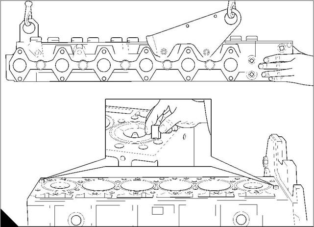
Warning! The cylinder head weighs 77 kg (170 lbs). Use lift equipment or obtain assistance to lift the cylinder head. |
|
1 Drain the cooling system. |
|
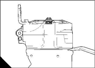
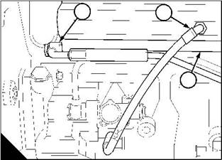
2 Disconnect the high-pressure oil pipe (A1) at the supply manifold (A3). 3 Disconnect the fuel pipe (A2) at the supply manifold (A3). 4 Remove the rocker cover, see Operation 3-1. |
|
5 Remove the rocker shaft assembly, see Operation 3-4. 6 Remove all the push rods and record their relative positions. 7 Remove all the pipes and hoses from the turbocharger. |
|
8 Remove the exhaust manifold setscrews and remove the exhaust manifold and turbocharger as an assembly. Remove the gasket for the exhaust manifold. |
|
9 Release evenly and gradually then remove the cylinder head setscrews together with their washers. 10 Carefully separate the cylinder head from the cylinder block with a suitable lever (B). 11 Remove the cylinder head. |
|
Caution: Put the cylinder head on blocks of wood to protect the tips of the fuel injector units. |
|
2 |
|
1 |
|
3 |
|
A |
|
B |
|
W211/1 |
|
W207 |
|
Workshop Manual, TPD 1353E, Issue 3 |
|
29 |
|
This document has been printed from SPI². Not for Resale |
![]()
![]()
![]()
![]()
|
3 |
|
Peregrine EDi and 1300 Series EDi |
|
To fit |
|
Operation 3-9 |
|
Special requirements |
|
Special tools |
|
Description |
|
Part number |
|
Cylinder head setscrew test tool |
|
27610202 |
|
Warning! The cylinder head weighs 77 kg (170 lbs). Use lift equipment or obtain assistance to lift the cylinder head. |
|
1 Clean the bottom face of the cylinder head and the top face of the cylinder block. Ensure that there is no debris in the cylinder bores. Ensure that the holes for the cylinder head setscrews are dry and free from debris. |
|
2 Fit the thermostat, if it was removed earlier. 3 Check the cylinder liner protrusion, see Operation 7-4. 4 Fit the dowels into the cylinder block (A). |
|
5 Fit a new cylinder head gasket onto the dowels (A). 6 Put the cylinder head in position (A). |
|
7 Fit the rocker shaft assembly, see Operation 3-5. |
|
8 Lightly lubricate with clean engine oil the setscrew threads, the setscrew head seating areas, and the washers. |
|
A |
|
W208 |
|
Continued |
|
30 |
|
Workshop Manual, TPD 1353E, Issue 3 |
|
This document has been printed from SPI². Not for Resale |
![]()
![]()
![]()
![]()
|
3 |
|
Peregrine EDi and 1300 Series EDi |
|
9 For WK, WL, WM, and WN engines: tighten evenly and gradually all of the cylinder head setscrews as follows: |
|
l 150 Nm (110 lbf ft) 15 kgf m in the sequence shown in (B) l 210 Nm (155 lbf ft) 21,5 kgf m in the sequence shown in (B) l 225 Nm (165 lbf ft) 23,0 kgf m in the sequence shown in (B) l Then proceed to step 13. |
|
10 For WP, WQ, WR and WS engines: Position the crankshaft at TDC for number 1 cylinder, and then rotate the crankshaft 30° past TDC. |
|
Caution: As the cylinder head setscrews are tightened to yield point, the setscrews must be tested for extension by use of special tool (27610202). Renew any setscrew that fails. If the special tool is not available, then all of the setscrews must be renewed. |
|
11 The threaded special tool is fitted on to each cylinder head setscrew. The setscrew must be renewed if the tool becomes tight on the setscrew thread. This tightness indicates that the setscrew thread is extended and the setscrew must be discarded. |
|
20 19 |
|
12 11 |
|
4 3 |
|
5 6 |
|
13 14 |
|
21 22 |
|
24 23 |
|
16 15 |
|
8 7 |
|
1 2 |
|
9 10 |
|
17 18 |
|
25 26 |
|
B |
|
W1382 |
|
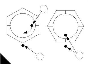
12 The cylinder head setscrews must be tightened as follows. Tighten evenly all of the setscrews in the sequence shown in (B) to 135 Nm (100 lbf ft) 13,8 kgf m. |
|
l Tighten each cylinder head setscrew to 177 Nm (130 lbf ft) 18 kgf m in the sequence shown in (B). l Repeat this step to ensure even tightness. |
|
l Tighten the setscrews in the same sequence by a further 90°. To do this, apply a mark (C1) to each setscrew head or socket spanner, and another mark (C2) at 90° clockwise on the cylinder head surface as shown. Tighten each setscrew until the two marks align. |
|
Caution: Chlorinated solvents must not be used on setscrews or crankcase tapped holes. Components should be clean and dry, and free of any chemical contamination other than engine oil. |
|
1 |
|
3 |
|
2 |
|
C |
|
W1383 |
|
Continued |
|
Workshop Manual, TPD 1353E, Issue 3 |
|
31 |
|
This document has been printed from SPI². Not for Resale |
![]()
![]()

|
3 |
|
Peregrine EDi and 1300 Series EDi |
|
13 Remove both of the feeler gauges from the rocker shaft, see Operation 3-5. |
|
14 Check the rocker levers for free movement. |
|
15 Set the valve tip clearance, see Operation 3-21. 16 Fit the high-pressure oil pipe at the supply manifold. 17 Fit the fuel pipe at the supply manifold. |
|
18 Fit the rocker cover, see Operation 3-2. |
|
19 Fit the gasket for the exhaust manifold. Fit the exhaust manifold and turbocharger assembly. Fit and tighten the setscrews for the exhaust manifold to 81 Nm (60 lbf ft) 8,3 kgf m. |
|
20 Fit all of the pipes and hoses removed earlier from the turbocharger. 21 Fill the cooling system. |
|
22 Eliminate air from the fuel system, see Operation 11-9. |
|
32 |
|
Workshop Manual, TPD 1353E, Issue 3 |
|
This document has been printed from SPI². Not for Resale |
![]()
![]()
|
3 |
|
Peregrine EDi and 1300 Series EDi |
|
Valves and valve springs |
|
To remove |
|
Operation 3-10 |
|
Warning! Eye protection must be worn during this operation. |
|
1 Remove the cylinder head, see Operation 3-8. Put the cylinder head on a surface that will not damage its face. |
|
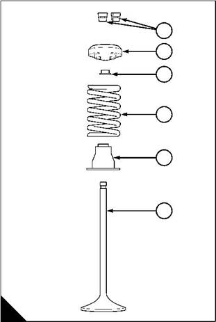
2 Use a valve spring compressor to compress the valve spring. 3 Remove the collets (A1). |
|
4 Release and remove the valve spring compressor. |
|
5 Remove the valve rotator (A2), the valve rotator seal (A3), the valve spring (A4), the valve seal assembly (A5) and the valve (A6). |
|
6 Separate the inlet valve springs from the exhaust valve springs. They are rated differently. 7 Discard the valve seal assemblies. |
|
1 2 |
|
3 |
|
4 |
|
5 6 |
|
A |
|
W077 |
|
Workshop Manual, TPD 1353E, Issue 3 |
|
33 |
|
This document has been printed from SPI². Not for Resale |
![]()
![]()
![]()
![]()

|
3 |
|
Peregrine EDi and 1300 Series EDi |
|
To fit |
|
Operation 3-11 |
|
Warning! Eye protection must be worn during this operation. 1 Ensure that the valve guides are clean. |
|
2 Apply clean lubricating oil to the valve stems and fit the valves (A6) into the valve guides. |
|
3 Apply clean lubricating oil to the inside of new valve seal assemblies (A5) and fit them to the valve stems. Ensure that each valve seal assembly is fitted fully into the valve spring recess in the cylinder head. |
|
4 Put the valve springs (A4) in position on the valve seal assemblies. |
|
Caution: Ensure that the inlet valve springs are fitted to inlet valves and that the exhaust valve springs are fitted to exhaust valves. They are rated differently. |
|
5 Fit new seals (A3) to the valve rotators (A2) and put the rotators onto the valve springs. 6 Use a valve spring compressor to compress each valve spring. 7 Fit the collets (A1). |
|
8 Release and remove the valve spring compressor. |
|
1 2 |
|
3 |
|
4 |
|
5 6 |
|
A |
|
W077 |
|
34 |
|
Workshop Manual, TPD 1353E, Issue 3 |
|
This document has been printed from SPI². Not for Resale |
![]()
![]()
![]()
![]()
|
3 |
|
Peregrine EDi and 1300 Series EDi To inspect and to correct |
|
Operation 3-12 |
|
Special requirements Special tools |
|
Description |
|
Part number |
|
21825617 and 21825496 |
|
Valve depth gauge |
|
1 Remove the cylinder head, see Operation 3-8. |
|
2 Put a small amount of low viscosity oil, for example calibration fluid, into the inlet and exhaust ports then check for leakage. |
|
3 Wait five minutes, then check again for leakage. |
|
Note: If no oil leaks past the valve seat, it does not need to be reground. |
|
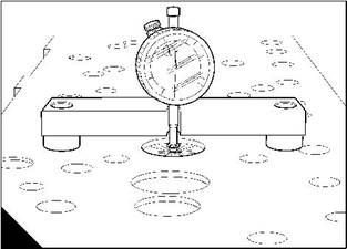
4 Ensure that the heads of the valves and the face of the cylinder head are clean. |
|
5 Check the depth of the valves below the face of the cylinder head before the valve springs are removed. Put the valve depth gauge on the face of the cylinder head and set the dial gauge to zero. Carefully put the valve depth gauge in position over the head of each valve (A) and compare the measurement with the relevant Data and dimensions for the "Inlet and exhaust valves" on page 10. |
|
6 If a valve is below the depth limit, check the valve depth with a new valve in position. 7 If the valve depth is still below the limit, the valve seat insert must be renewed, see Operation 3-19. 8 Remove the valves and valve springs, see Operation 3-10. |
|
9 Visually inspect the condition of the collets. |
|
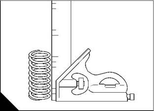
10 Visually inspect the valve springs for corrosion, for damage or distortion. 11 Check that the end faces of the springs are square and flat. |
|
12 Measure the free length of the valve springs (B) and compare it with the relevant Data and dimensions for the "Valve guides and springs" on page 11. |
|
A |
|
B |
|
W131 |
|
W112 |
|
Continued |
|
Workshop Manual, TPD 1353E, Issue 3 |
|
35 |
|
This document has been printed from SPI². Not for Resale |
![]()
![]()
![]()
![]()
|
3 |
|
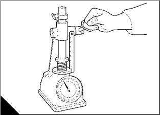
Peregrine EDi and 1300 Series EDi |
|
13 Measure the springs under a load (C), refer to the relevant Data and dimensions for the "Valve guides and springs" on page 11. |
|
14 Check the valves for cracks. Check the stems for wear and correct fit in their valve guides. |
|
15 Check that the seat faces of the valves are not badly burnt or damaged. Seat faces of valves that are damaged can be ground on a special machine. Valves that have only a little damage can be lapped to their valve seats. When new valves are fitted, the valve depths must be checked. |
|
16 Measure the valve dimensions and compare them with the relevant Data and dimensions for the "Inlet and exhaust valves" on page 10. |
|
C |
|
W113 |
|
36 |
|
Workshop Manual, TPD 1353E, Issue 3 |
|
This document has been printed from SPI². Not for Resale |
![]()
![]()
|
3 |
|
Peregrine EDi and 1300 Series EDi |
|
To inspect a valve rotator |
|
Operation 3-13 |
|
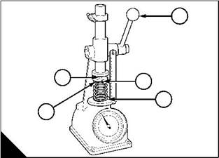
1 Visually inspect the valve rotator for corrosion, damage or distortion. |
|
2 To test the operation of the rotator (A4), put a valve spring (A3), the valve rotator and a steel ball bearing (A5) in a valve spring tester (A1). |
|
3 Mark the rotator with a reference line (A2). |
|
4 Compress the valve spring rapidly several times and check that the rotator rotates. 5 Replace any rotator that does not rotate. |
|
1 |
|
5 |
|
2 |
|
3 |
|
4 |
|
A |
|
W114 |
|
Workshop Manual, TPD 1353E, Issue 3 |
|
37 |
|
This document has been printed from SPI². Not for Resale |
![]()
![]()
![]()
![]()
|
3 |
|
Peregrine EDi and 1300 Series EDi |
|
Valve guides |
|
To inspect a valve guide |
|
Operation 3-14 |
|
Check the valve guides for wear. The maximum clearance between the valve stem and the bore of the guide is 0,15 mm (0.006 in) for the inlet valves and the exhaust valves. |
|
If the clearance with new valves fitted is more than the limit, then a new valve guide must be fitted. |
|
38 |
|
Workshop Manual, TPD 1353E, Issue 3 |
|
This document has been printed from SPI². Not for Resale |
![]()
![]()
![]()
![]()
|
3 |
|
Peregrine EDi and 1300 Series EDi |
|
To remove |
|
Operation 3-15 |
|
Special requirements |
|
Special tools Part number |
|
Description |
|
Description |
|
Part number |
|
Remover / replacer for valve guides |
|
21825478 |
|
Adaptor |
|
21825479 |
|
1 Fit the adaptor 21825479 (A4) into the remover / replacer tool 21825478 (A3). Pass the tool and adapter through the spacer (A5) and the cylinder head, from the bottom face. Fully fit the attachment (A7) to secure the adapter in the valve guide (A6). |
|
2 Turn the top handle (A1) to take up the excess movement in the tool and turn the bottom handle (A2) to pull the valve guide out of the cylinder head. |
|
1 |
|
2 |
|
3 |
|
4 5 |
|
6 7 |
|
A |
|
W132 |
|
Workshop Manual, TPD 1353E, Issue 3 |
|
39 |
|
This document has been printed from SPI². Not for Resale |