 English
 Espaol
 Franais
 阿拉伯
阿拉伯 中文
中文 Deutsch
 Italiano
 Português
 日本
日本 韩国
韩国 български
 hrvatski
 esky
esky Dansk
Dansk Nederlands
 suomi
suomi Ελληνικ
 印度
印度 norsk
norsk Polski
 Roman
Roman русский
 Svenska
Perkins1206-E70TTA柴油发动机燃油泵与喷油器供应商,Perkins1206-E70TTA柴油发动机燃油泵与喷油器技术价格规格咨询服务,Perkins1206-E70TTA柴油发动机燃油泵与喷油器零配件供应,Perkins1206-E70TTA柴油发动机燃油泵与喷油器售后服务中心,Perkins1206-E70TTA柴油发动机燃油泵与喷油器,Perkins1206-E70TTA柴油发动机燃油泵与喷油器详细的技术参数,

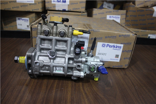
Perkins1206-E70TTA柴油发动机燃油泵与喷油器
详细描述
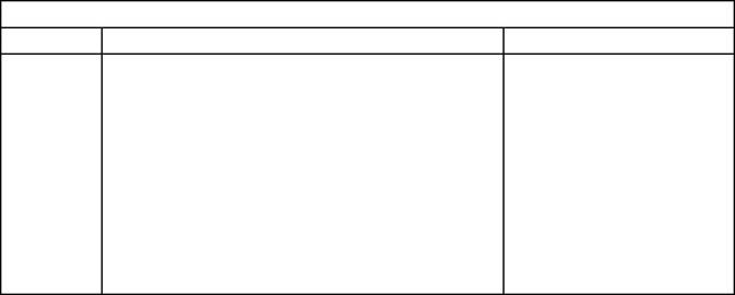
项目 零配件号码 新件号 描述
1 T406274 1 T406274 燃油轨条
5 2314 H006 3 2314 H006 螺拴
6 T405864 1 T405864 管 - 燃油的喷射
14 2314 F004 1 2314 F004 螺旋
15 T407161 1 T407161 管 - 燃油的喷射
21 2314 F004 2 2314 F004 螺旋
22 T410437 1 T410437 保护装备
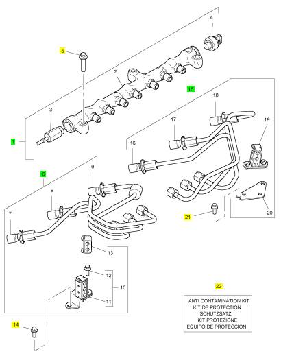
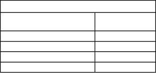
项目 零配件号码 新件号 描述
2 1 燃油轨条
3 T405398 1 T405398 放泄阀
4 1 感应传感器

项目 零配件号码 新件号 描述
7 T408500 1 T408500 以管输送 - 燃油 INJ 没有 1 CYL
8 T408506 1 T408506 以管输送 - 燃油 INJ 没有 2 CYL
9 T408501 1 T408501 以管输送 - 燃油 INJ 没有 3 CYL
10 T407687 1 T407687 管夹
13 T411459 1 T411459 管夹
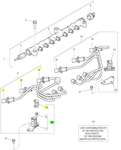
项目 零配件号码 新件号 描述
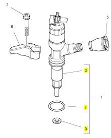
1 T409982 6 T409982 喷油器
5 T407139 1 T407139 绑腿
6 T406394 1 T406394 喷油器砂箱夹
7 3218 A016 1 3218 A016 螺旋
8 T410437 1 T410437 保护装备
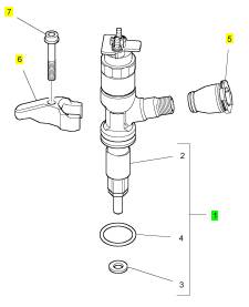
项目 零配件号码 新件号 描述
2 1 喷油器
3 T405750 1 T405750 喷油器垫圈
4 T406053 1 T406053 密封O型圈
项目 零配件号码 新件号 描述
1 T409125 6 T409125 GLOWPLUG
2 T406849 1 T406849 BUSBAR
3 3881 A006 1 3881 A006 绝缘体
4 2318 A207 1 2318 A207 螺帽
5 2314 C038 1 2314 C038 螺旋
6 2487 F201 1 2487 F201 帽

项目 零配件号码 新件号 描述
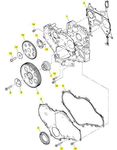
1 T407493 1 T407493 时间安排箱
2 T406050 1 T406050 密封垫片 - 正时齿轮箱
3 T407454 1 T407454 正时齿轮盖
4 T405824 1 T405824 密封垫片 - 正时齿轮箱盖
5 T406781 1 T406781 密封 -前油封
6 T406093 1 T406093 惰轮传动机构
7 T416351 1 T416351 轮毂
7 T406834 1 T416351 轮毂
8 T406040 1 T406040 板
9 2314 J010 3 2314 J010 螺旋
10 T407464 1 T407464 凸轮轴传动机构
11 3112 X011 1 3112 X011 推力垫圈
12 3321 A003 1 3321 A003 垫圈
13 2314 J606 1 2314 J606 螺旋
14 2314 H003 7 2314 H003 螺旋
15 2314 H006 2 2314 H006 螺拴
16 2314 H034 3 2314 H034 螺旋
17 2314 H012 6 2314 H012 螺旋
18 2314 H003 10 2314 H003 螺旋
19 2116053 1 2116053 合钉
项目 零配件号码 新件号 描述
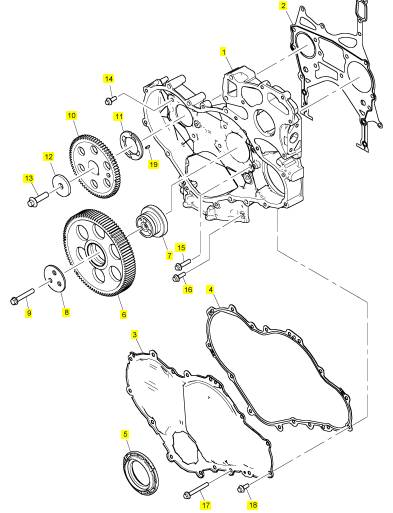
1 T407493 1 T407493 时间安排箱
2 T406050 1 T406050 密封垫片 - 正时齿轮箱
3 T410622 1 T410622 正时齿轮盖
4 T405824 1 T405824 密封垫片 - 正时齿轮箱盖
5 T410666 1 T410666 密封 -前油封
6 T406093 1 T406093 惰轮传动机构
7 T416351 1 T416351 轮毂
7 T406834 1 T416351 轮毂
8 T406040 1 T406040 板
9 2314 J010 3 2314 J010 螺旋
10 T407464 1 T407464 凸轮轴传动机构
11 3112 X011 1 3112 X011 推力垫圈
12 3321 A003 1 3321 A003 垫圈
13 2314 J606 1 2314 J606 螺旋
14 2314 H003 7 2314 H003 螺旋
15 2314 H006 2 2314 H006 螺拴
16 2314 H034 3 2314 H034 螺旋
17 2314 H012 6 2314 H012 螺旋
18 2314 H003 10 2314 H003 螺旋
19 2116053 1 2116053 合钉
项目 零配件号码 新件号 描述
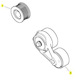
1 T405103 1 T405103 皮带轮
2 T410698 1 T410698 张紧轮
项目 零配件号码 新件号 描述
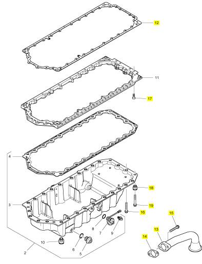
1 1 油底壳
12 3681 K044 1 3681 K044 密封垫片 -油底壳
13 3575 A074 1 3575 A074 管 - 油的吸入
14 3683 H005 1 3683 H005 密封垫片
15 2314 H004 2 2314 H004 螺旋
16 2314 H007 2 2314 H007 螺旋
17 2316 T052 6 2316 T052 螺旋
18 T407498 4 T407498 限制器
19 2314 K161 28 2314 K161 螺旋
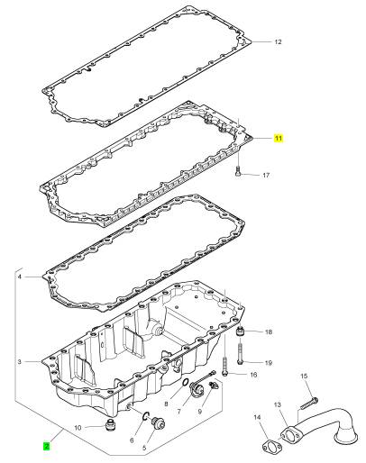
项目 零配件号码 新件号 描述
2 T405964 1 T405964 油底壳
11 T406564 1 T406564 污水坑承接器
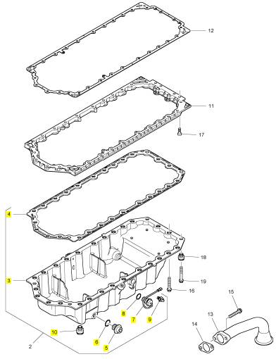
项目 零配件号码 新件号 描述
3 1 油底壳
4 3681 K041 1 3681 K041 密封垫片 -油底壳
5 32186405 2 32186405 栓塞
6 T407088 2 T407088 密封O型圈
7 T405544 1 T405544 开关
8 CH12137 1 CH12137 密封O型圈
9 2817 A002 1 2817 A002 接线夹
10 T407498 26 T407498 限制器
|
System Configuration Parameters |
|
System Configuration Parameters |
|
The rating code is not reprogrammed when the replacement ECM is for the same engine rating. |
|
If the ECM is for a different engine rating, then the following components may require replacement: pistons, fuel injectors and other components. The engine information ratings plate must also be changed in order to reflect the new rating. |
|
i04735910 |
|
Some systems such as the cooling system or the transmission may also require changes when the engine is rerated. Contact the local OEM dealer for further information. |
|
System Configuration Parameters |
|
“Engine Serial Number” |
|
System configuration parameters affect the emissions of the engine or the power of the engine. System configuration parameters are programmed at the factory. Normally, system configuration parameters would never change through the life of the engine. System configuration parameters must be |
|
When a new ECM is delivered, the engine serial number in the ECM is not programmed. The “Engine Serial Number” should be programmed to match the engine serial number that is stamped on the engine information plate. |
|
reprogrammed if an Electronic Control Module (ECM) is replaced. System configuration parameters are not reprogrammed if the ECM software is changed. Factory passwords are required to change these parameters. The following information is a description of the system configuration parameters. |
|
Factory Installed Aftertreatment#1 IdentificationNumber |
|
The “Factory Installed Aftertreatment #1 Identification Number” parameter ensures that the correct aftertreatment package is installed. |
|
“Full Load Setting” |
|
DPF #1 Soot Loading Sensing System ConfigurationCode |
|
The “Full Load Setting” is a number that represents the factory adjustment to the fuel system in order to fine-tune the fuel system. If the ECM is replaced, the “full load setting” must be reprogrammed in order to prevent a 630-2 diagnostic code from becoming active. |
|
The “DPF #1 Soot Loading Sensing System Configuration Code” is used to determine the type of diesel particulate filter soot loading sensing system . This code is a combination of two letters that identifies the orientation of the soot sensor and the geometry of the DPF. This code is used by the ECM software to identify the correct calibration table in order to match the soot sensor system to the DPF. The calibration table optimizes the soot readings and the regeneration cycles. |
|
“Full Torque Setting” |
|
“Full Torque Setting” is like “Full Load Setting” . If the ECM is replaced, the full torque setting must be reprogrammed in order to prevent a 630-2 diagnostic code from becoming active. |
|
Limp Home Engine Speed |
|
“Rating” |
|
The “Limp Home Engine Speed” is the maximum engine speed allowed when the engine has been derated. |
|
The “Rating” is a code that prevents the use of an incorrect power rating and/or emission rating for a specific engine. Each horsepower rating and each emission certification have a different code to all other horsepower ratings and emission certifications. This rating is a code that prevents the use of an incorrect power rating and/or emission rating for a specific engine. |
|
Limp Home Engine Speed Ramp Rate |
|
The “Limp Home Engine Speed Ramp Rate” is the rate at which the engine speed decelerates when the engine has been derated. |
|
When an ECM is replaced, this rating interlock code must match the code that is stored in the ECM. If the rating interlock code does not match the code that is stored in the ECM, both of the following situations will exist: |
|
“ECM Software Release Date” |
|
This parameter is defined by the rating interlock and this parameter is not programmable. The “ECM Software Release Date” is used to provide the version of the software. The Customer parameters and the software change levels can be monitored by this date. The date is provided in the month and the year (JAN10). Jan is the month (January). 10 is the year (2010). |
|
• The engine will not run. |
|
• The diagnostic code 631-2 Calibration Module : Erratic, Intermittent, or Incorrect will be active. |
|
Note: The flash programming of a new rating interlock replaces the old rating interlock . |
|
This document is printed from SPI². Not for RESALE |
![]()
|
KENR9101 |
|
59 |
|
Symptom Troubleshooting |
|
Symptom Troubleshooting |
|
Display on the Control Panel |
|
Note: The following procedure is only applicable if the application is equipped with a display on the control panel. |
|
i04807918 |
|
1. Check the display on the control panel for active |
|
Acceleration Is Poor or Throttle Response Is Poor |
|
diagnostic codes. |
|
2. Troubleshoot any active codes before continuing with this procedure. Refer to Troubleshooting, “Troubleshooting with a Diagnostic Code”. |
|
Probable Causes |
|
Flash Codes |
|
• Diagnostic codes |
|
Note: The following procedure is only applicable if the machine is equipped with the appropriate warning lamps. |
|
• Parameters in the Electronic Control Module (ECM) |
|
1. Check the warning lamps on the control panel for flash codes. Flash codes are explained in Troubleshooting, “Flash Codes”. |
|
• Electrical connectors • Air intake and exhaust system • Valve lash |
|
2. If any flash codes are displayed, troubleshoot the codes before continuing with this procedure. Refer to Troubleshooting, “Troubleshooting with a Diagnostic Code”. |
|
• Turbochargers |
|
• Fuel supply |
|
ECM Parameters |
|
• Low compression (cylinder pressure) • Electronic unit injectors • Individual malfunctioning cylinder |
|
1. Use the electronic service tool to make sure that the FLS and FTS parameters have been correctly entered. |
|
Recommended Actions |
|
2. Use the electronic service tool to ensure that the correct mode is selected on the Mode Selector Switch . |
|
NOTICE |
|
Do not crank the engine continuously for more than 30 seconds. Allow the starting motor to cool for two minutes before cranking the engine again. |
|
3. Use the electronic service tool to verify that the correct engine rating has been provided. |
|
4. Use the electronic service tool to verify the |
|
Diagnostic Codes |
|
maximum engine speed limit. |
|
5. Ensure that the repairs have restored the expected performance. |
|
Use one of the following methods to check for active diagnostic codes: |
|
• The electronic service tool |
|
6. If the repairs have not eliminated the faults, |
|
proceed to “Electrical Connectors”. |
|
• The display on the control panel |
|
Electrical Connectors |
|
• Flash Codes |
|
Electronic Service Tool |
|
1. Turn the start switch to the ON position. |
|
1. Connect the electronic service tool to the diagnostic connector. |
|
2. Use the electronic service tool to verify that the intake manifold pressure is zero ± 0.5 kPa (zero ± 0.070 psi). Check the 5 VDC sensor supply for the intake manifold pressure. Refer to Troubleshooting, “5 VDC Sensor Supply Circuit - Test”. |
|
2. Check for active diagnostic codes on the electronic service tool. |
|
3. Investigate any active codes before continuing with this procedure. Refer to Troubleshooting, |
|
“Troubleshooting with a Diagnostic Code”. |
|
This document is printed from SPI². Not for RESALE |
![]()
![]()
![]()
|
60 |
|
KENR9101 |
|
Symptom Troubleshooting |
|
3. Use the electronic service tool to verify the throttle |
|
position status. |
|
2. Check that the oil drains for the turbochargers are |
|
not blocked or restricted. |
|
4. Run the engine until the speed is equal to the |
|
3. Check that the compressor housings for the turbochargers are free of dirt and debris. Make sure that the housings are not damaged. |
|
maximum no-load speed. |
|
5. Use the electronic service tool to make sure that the throttle is set to reach the maximum no-load speed. |
|
4. Check that the turbine housings for the turbochargers are free of dirt and debris. Make sure that the housings are not damaged. |
|
6. If the maximum no-load speed cannot be obtained refer to Troubleshooting, “Throttle Switch Circuit - Test” and Troubleshooting, “Mode Selection Circuit - Test”. |
|
5. Check that the turbine blades rotate freely in the turbochargers. |
|
7. If the engine speed is erratic refer to Troubleshooting, “Analog Throttle Position Sensor Circuit - Test” or Troubleshooting, “Digital Throttle Position Sensor Circuit - Test”. |
|
6. Ensure that the wastegate on the high-pressure turbocharger is adjusted correctly. Refer to Systems Operation, Testing, and Adjusting, “Turbocharger - Inspect”. If the wastegate actuator is faulty, replace the turbocharger. Refer to Disassembly and Assembly, “Turbocharger - Remove” and Disassembly and Assembly, “Turbocharger - Install”. |
|
8. If the fault has not been eliminated, proceed to “Air Intake and Exhaust System”. |
|
Air Intake and Exhaust System |
|
7. If necessary, replace the faulty turbocharger. Refer to Disassembly and Assembly, “Turbocharger - Remove” and Disassembly and Assembly, “Turbocharger - Install”. |
|
1. Check the air filter restriction indicator, if equipped. 2. Ensure that the air filter is clean and serviceable. |
|
3. Check the air intake and the exhaust system for the following defects: |
|
8. Check that the repairs have eliminated the faults. |
|
9. If the fault has not been eliminated, proceed to “Fuel Supply”. |
|
• Blockages |
|
• Restrictions |
|
Fuel Supply |
|
• Damage to the air intake and exhaust lines and hoses |
|
1. Visually check the fuel tank for fuel. The fuel gauge |
|
may be faulty. |
|
4. Make all necessary repairs to the engine. |
|
2. Ensure that the fuel supply valve (if equipped) is in the full OPEN position. |
|
5. If the fault has not been eliminated, proceed to “Valve Lash”. |
|
3. If the temperature is below 0 °C (32 °F), check for solidified fuel (wax). |
|
Valve Lash |
|
1. Check the valve lash. Refer to Systems Operation, Testing, and Adjusting, “Engine Valve Lash - Inspect”. |
|
4. Check the primary filter/water separator for water in the fuel. |
|
5. Check for fuel supply lines that are restricted. |
|
2. If any repair does not eliminate the fault, proceed to “Turbochargers”. |
|
6. Check that the low-pressure fuel lines are tight and secured properly. |
|
Turbochargers |
|
7. Check that the Electric Fuel Lift Pump (EFLP) is operating. If the EFLP is suspect, refer to Troubleshooting, “Fuel Pump Relay Circuit - Test”. |
|
Note: The turbochargers that are installed on the engine are nonserviceable items. If any mechanical fault exists, then the faulty turbocharger must be replaced. |
|
8. Replace the in-line fuel strainer that is upstream of the primary fuel filter. |
|
1. Ensure that the mounting bolts for the turbochargers are tight. |
|
9. Replace the primary and secondary fuel filters. |
|
This document is printed from SPI². Not for RESALE |
![]()
|
KENR9101 |
|
61 |
|
Symptom Troubleshooting |
|
10. Check the diesel fuel for contamination. Refer to Systems Operation, Testing, and Adjusting, “Fuel Quality - Test”. |
|
2. Disconnect the TPIR return line from the drain port on the TPIR. Install a suitable blanking cap on the open port in the TPIR return line |
|
11. Check for air in the fuel system. Refer to Systems Operation, Testing, and Adjusting, “Air in Fuel - Test”. |
|
3. Connect a temporary drain line to the drain port on the TPIR. |
|
4. Place the end of the temporary drain line into a |
|
12. Ensure that the fuel system has been primed. Refer to Systems Operation, Testing, and Adjusting, “Fuel System - Prime”. |
|
suitable calibrated container. |
|
5. With the keyswitch in the ON position but the engine not running, use a suitable multimeter to measure the input voltage to the EFLP. Record the reading. |
|
13. If the fault is not eliminated, perform the following procedure: |
|
Note: Before performing the following fuel system tests, the engine must be run for a minimum of 30 minutes. |
|
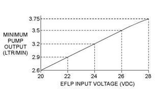
6. With the keyswitch in the ON position but the engine not running, measure the fuel flow from the temporary drain line. For a 12 VDCsystem, refer to Illustration 24 for the minimum acceptable flow rate. For a 24 VDC system, refer to Illustration 25 for the minimum acceptable flow rate. |
|
Note: When performing the following fuel system tests, the Electric Fuel Lift Pump (EFLP) will only operate for 2 minutes unless the engine is running. If necessary, cycle the keyswitch in order to reactivate the pump. |
|
Illustration 24 |
|
g02355128 |
|
Minimum TPIR flow rate for a 12 VDC system |
|
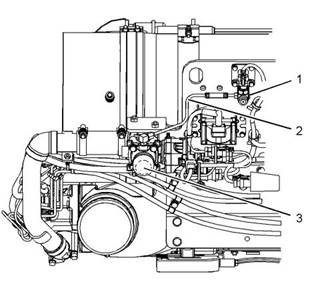
Illustration 23 |
|
g02873776 |
|
(1) Return line pressure relief valve (2) Secondary fuel filter base (3) Transfer pump inlet regulator (TPIR) (4) Transfer pump inlet regulator return port |
|
Transfer Pump Inlet Regulator (TPIR) Flow Test |
|
Refer to Illustration 23 . |
|
Illustration 25 |
|
g02355130 |
|
Perform the following procedure: |
|
Minimum TPIR flow rate for a 24 VDC system |
|
1. Make sure the keyswitch is in the OFF position. |
|
7. Remove the temporary drain line from the drain port on the TPIR. Connect the TPIR return line to the TPIR. |
|
This document is printed from SPI². Not for RESALE |
![]()
![]()
![]()

![]()
![]()
![]()
![]()
|
62 |
|
KENR9101 |
|
Symptom Troubleshooting |
|
8. If the fuel flow in Step 6 is greater than the minimum limit, proceed to “Low Compression (Cylinder Pressure)”. |
|
EFLP Flow Test at the Primary Fuel Filter Inlet |
|
In order to check the fuel flow from the EFLP at the primary fuel filter inlet, perform the following procedure: |
|
9. If the fuel flow in Step 6 is below the minimum limit, proceed to “Return Line Pressure Relief Valve Test”. |
|
1. Make sure the keyswitch is in the OFF position. |
|
10. If there is no fuel flow in Step 6, proceed to “Transfer Pump Inlet Regulator (TPIR) Return Test”. |
|
2. Disconnect the fuel inlet connection from the primary fuel filter head. |
|
3. Install a suitable blank on the fuel inlet port on the primary fuel filter head. |
|
Transfer Pump Inlet Regulator (TPIR) Return Test |
|
4. Place the open end of the fuel inlet line in a suitable |
|
In order to check the return flow from the TPIR, perform the following procedure: |
|
calibrated container. |
|
5. With the keyswitch in the ON position, measure the input voltage at the EFLP. Record the result. |
|
1. Make sure that the TPIR return line is not blocked or kinked. |
|
6. With the keyswitch in the ON position, measure the flow from the fuel inlet line. Record the result. |
|
2. If the TPIR return line is clear, confirm that the Electric Fuel Lift Pump (EFLP) is operating. Make sure that fuel lines between the EFLP and the TPIR are not blocked or kinked. |
|
7. Check the recorded voltage and fuel flow on the graph in Illustration 26 |
|
3. If the fuel lines to the TPIR are clear and the EFLP is operating, replace the TPIR. |
|
4. If the fault is still present, proceed to “Low Compression (Cylinder Pressure)”. |
|
Return Line Pressure Relief Valve Test |
|
In order to check the return line pressure relief valve in the secondary fuel filter base, perform the following procedure: |
|
1. Make sure the keyswitch is in the OFF position. |
|
2. Disconnect the return line banjo connection on the |
|
top of the secondary fuel filter. |
|
Illustration 26 |
|
g02527498 |
|
Minimum EFLP flow rate for a 12 VDC system |
|
3. Use a suitable blank to plug the return line. |
|
4. Install a suitable drain line to the return line point on the top of the secondary fuel filter. |
|
5. Place the open end of the drain line in a suitable calibrated container. |
|
6. With the keyswitch in the ON position, measure the flow from the drain line. |
|
7. If the flow from the drain line is less than 0.4 L (24.4 cubic inch) per minute, proceed to “EFLP Flow Test at the Primary Fuel Filter Inlet”. |
|
8. If the flow from the drain line is more than 0.4 L (24.4 cubic inch) per minute, replace the secondary fuel filter head. Refer to Disassembly and Assembly, “Fuel Filter Base - Remove and Install”. |
|
Illustration 27 |
|
g02527518 |
|
Minimum EFLP flow rate for a 24 VDC system |
|
This document is printed from SPI². Not for RESALE |
![]()

![]()
![]()

![]()
![]()
|
KENR9101 |
|
63 |
|
Symptom Troubleshooting |
|
8. If the fuel flow is below the minimum value for the recorded voltage, replace the EFLP. Refer to Disassembly and Assembly, “Fuel Priming Pump - Remove and Install”. |
|
1. Use the electronic service tool to perform the |
|
automatic “Cylinder Cut Out Test” . If the compression test that was performed in “Low Compression (Cylinder Pressure)” was satisfactory, the “Cylinder Cut Out Test” will identify any faulty injectors. |
|
9. If the fuel flow is above the minimum value for the recorded voltage, proceed to “Check the Return Fuel Lines”. |
|
2. Remove any faulty electronic unit injectors. Refer to Disassembly and Assembly, “Electronic Unit Injector - Remove”. |
|
Check the Return Fuel Lines |
|
3. Install new electronic unit injectors. Refer to Disassembly and Assembly, “Electronic Unit Injector - Install”. |
|
1. Make sure that the TPIR return line is not blocked or kinked. |
|
2. Make sure that fuel lines between the EFLP and |
|
the TPIR are not blocked or kinked. |
|
4. Repeat the test in 1. If the fault is still apparent, remove the replacement electronic unit injector and install the original electronic unit injector. Refer to Disassembly and Assembly, “Electronic Unit Injector - Remove” and Disassembly and |
|
3. If the fuel lines to the TPIR are clear and the EFLP is operating, replace the TPIR. |
|
4. If the fault is still present, proceed to “Low Compression (Cylinder Pressure)”. |
|
Assembly, “Electronic Unit Injector - Install”. |
|
5. If the repair does not eliminate the fault, refer to “Individual Malfunctioning Cylinders”. |
|
Low Compression (Cylinder Pressure) |
|
1. Perform a compression test. Refer to Systems Operation, Testing, and Adjusting, “Compression - Test”. |
|
Individual MalfunctioningCylinders |
|
1. With the engine speed at a fast idle, use the electronic service tool to perform the manual “Cylinder Cut Out Test” . As each cylinder is cut out, listen for a change in the sound from the engine. When a cylinder is cut out, there should be a noticeable change in the sound of the engine. If a change in the sound of the engine is not noted, the isolated cylinder is not operating under normal conditions. If the isolation of a cylinder results in a change in the sound that is less noticeable, the cylinder may be operating below normal |
|
2. If low compression is noted on any cylinders, investigate the cause and rectify any faults. |
|
Possible causes of low compression are shown in the following list: |
|
• Loose glow plugs |
|
• Faulty piston |
|
• Faulty piston rings |
|
performance. Investigate the cause of the fault on any cylinder that is not operating. Investigate the cause of the fault on any cylinder that is operating below normal performance. |
|
• Worn cylinder bores |
|
• Worn valves |
|
• Faulty cylinder head gasket • Damaged cylinder head 3. Perform all necessary repairs. 4. Ensure that the repairs have eliminated the faults. |
|
2. If the fault is still present, contact Perkins Global Technical Support. |
|
i04079191 |
|
Alternator Is Noisy |
|
5. If no faults are detected, proceed to “Electronic Unit |
|
Injectors”. |
|
Refer to Systems Operation, Testing, and Adjusting for information on possible electrical causes of this condition. |
|
Electronic Unit Injectors |
|
This document is printed from SPI². Not for RESALE |
![]()
|
64 |
|
KENR9101 |
|
Symptom Troubleshooting |
|
Probable Causes • Alternator drive belt |
|
Recommended Actions |
|
Alternator Drive Belt |
|
• Alternator mounting bracket • Alternator drive pulley • Alternator bearings |
|
Inspect the condition of the alternator drive belt. If the alternator drive belt is worn or damaged, check that the drive belt for the alternator and the pulley are correctly aligned. If the alignment is correct, replace the drive belt. Refer to Disassembly and Assembly, “Alternator Belt - Remove and Install”. |
|
Recommended Actions |
|
Charging Circuit |
|
Alternator Drive Belt |
|
Inspect the battery cables, wiring, and connections in the charging circuit. Clean all connections and tighten all connections. Replace any faulty parts. |
|
Inspect the condition of the alternator drive belt. If the alternator drive belt is worn or damaged, check that the drive belt for the alternator and the pulley are correctly aligned. If the alignment is correct, replace the drive belt. Refer to Disassembly and Assembly, “Alternator Belt - Remove and Install”. |
|
Alternator |
|
Verify that the alternator is operating correctly. Refer to Systems Operation, Testing, and Adjusting, “Alternator - Test”. The alternator is not a serviceable item. The alternator must be replaced if the alternator is not operating correctly. Refer to Disassembly and Assembly, “Alternator - Remove” and Disassembly |
|
Alternator Mounting Bracket |
|
Inspect the alternator mounting bracket for cracks and wear. Repair the mounting bracket or replace the mounting bracket. Ensure that the alternator drive belt and the alternator drive pulley are in alignment. |
|
and Assembly, “Alternator - Install”. |
|
i04003176 |
|
ARD Combustion Supply Air Pressure Is Low |
|
Alternator Drive Pulley |
|
Remove the nut for the alternator drive pulley and then inspect the nut and the drive shaft. If no damage is found, install the nut and tighten the nut to the correct torque. Refer to Disassembly and Assembly, “Alternator - Install” for the correct torque. |
|
System Operation Description: |
|
This procedure covers the following diagnostic trouble code: |
|
Alternator Bearings |
|
Check for excessive play of the shaft in the alternator. Check for wear in the alternator bearings. The alternator is a nonserviceable item. The alternator must be replaced if the bearings are worn. Refer to Disassembly and Assembly, “Alternator - Remove” and Disassembly and Assembly, “Alternator - Install”. |
|
i04079192 |
|
Alternator Problem |
|
Probable Causes • Alternator drive belt • Charging circuit • Alternator |
|
This document is printed from SPI². Not for RESALE |
![]()
|
KENR9101 |
|
65 |
|
Symptom Troubleshooting |
|
Table 85 |
|
Diagnostic Trouble Codes for ARD Combustion Supply Air Pressure Is Low |
|
J1939 Code |
|
Code Description |
|
Comments |
|
3837-17 |
|
Aftertreatment#1 Secondary Air Pressure : Low - least severe |
|
The air pressure that is supplied to the ARD falls below a minimum acceptable value that is calculated by the ECM. |
|
One or more of the following codes will al- ways be present: |
|
102-18 |
|
3473-31 3474-31 3711-31 |
|
The diagnostic code will be reset when a successful regenerationhas occurred or the fault has been rest by the electronic service tool. |
|
Table 86 |
|
Associated Diagnostic Trouble Code |
|
Suspect Parameter Number (SPN) |
|
Failure Mode Identi- fier (FMI) |
|
102 3473 3474 3711 |
|
18 31 31 31 |
|
Results: |
|
• An associated diagnostic trouble code is not present. Proceed to Test Step 2. |
|
• An associated diagnostic trouble code is present. |
|
Repair: Troubleshoot the associated code. Refer to TroubleshootingDiagnostic Trouble Codes. |
|
Illustration 28 |
|
g01994613 |
|
Components of the ARD combustion air supply |
|
STOP. |
|
The combustion air valve (3) receives operating voltage from the engine ECM. The combustion air valve sends a position signal to the engine ECM. An ARD air pressure sensor (1) sends a pressure signal to the engine ECM. The ECM uses the pressure signal to determine the volume of combustion air that is being provided to the combustion air valve. The ECM controls the position of the combustion air valve in order to provide the correct volume of combustion air to the ARD. |
|
Test Step 2. Inspect the Piping Between the High Pressure Turbocharger and the Combustion Air Valve |
|
A. Inspect the piping between the high-pressure turbocharger and the combustion air valve. |
|
B. Check for cracks in the piping. C. Check for loose joints or damaged joints. Expected Result: |
|
Test Step 1. Check for Associated Diagnostic Trouble Codes |
|
Table 86 lists the diagnostic trouble codes that are associated with a 3837-17 code. Determine if a code in Table 86 is present. |
|
The piping is damaged or cracked. Results: |
|
This document is printed from SPI². Not for RESALE |
![]()
![]()
![]()
|
66 |
|
KENR9101 |
|
Symptom Troubleshooting |
|
• The piping is damaged or cracked. |
|
STOP. |
|
i04807925 |
|
Repair: Replace the piping or repair the piping. |
|
Proceed to Test Step 4. |
|
ARD Failed to Ignite |
|
• The piping is not damaged or cracked. Proceed to Test Step 3. |
|
System Operation Description: |
|
Test Step 3. Inspect the Piping from the Combustion Air Valve to the Pressure Sensor |
|
Use this procedure to troubleshoot the following code: |
|
A. Inspect the piping (2) from the combustion air valve to the pressure sensor. |
|
B. Check for cracks in the piping. C. Check for air leaks. |
|
D. Check the clamps on the piping. Make sure that the clamps are tight. |
|
Results: |
|
• The piping is damaged or cracked. |
|
Repair: Replace the piping or repair the piping. Proceed to Test Step 4. |
|
• The piping is not damaged. Proceed to Test Step 4. |
|
Test Step 4. Perform the “ARD Air System Service Test” |
|
Use the electronic service tool to perform the ARD Air System Service Test. |
|
Results: |
|
• The ARD Air System Service Test is successful. |
|
Repair: Use the electronic service tool in order to perform a “manual regeneration” and return the unit to service. |
|
STOP. |
|
• The ARD Air System Service Test did not complete successfully. – The combustion air valve is faulty. |
|
Repair: |
|
A. Replace the combustion air valve. Refer to Disassembly and AssemblyAir Control Valve - Remove and Install. |
|
B. Repeat this Test Step in order to confirm that the fault has been eliminated. |
|
C. If the fault is still present, contact Perkins Global Technical Support. This document is printed from SPI². Not for RESALE |