 English
 Espaol
 Franais
 阿拉伯
阿拉伯 中文
中文 Deutsch
 Italiano
 Português
 日本
日本 韩国
韩国 български
 hrvatski
 esky
esky Dansk
Dansk Nederlands
 suomi
suomi Ελληνικ
 印度
印度 norsk
norsk Polski
 Roman
Roman русский
 Svenska
Perkins1206-E70TTA柴油发动机摇臂供应商,Perkins1206-E70TTA柴油发动机摇臂技术价格规格咨询服务,Perkins1206-E70TTA柴油发动机摇臂零配件供应,Perkins1206-E70TTA柴油发动机摇臂售后服务中心,Perkins1206-E70TTA柴油发动机摇臂,Perkins1206-E70TTA柴油发动机摇臂详细的技术参数,

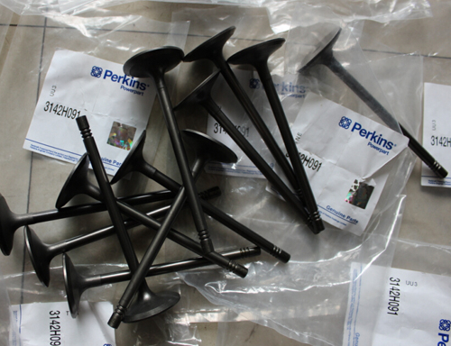
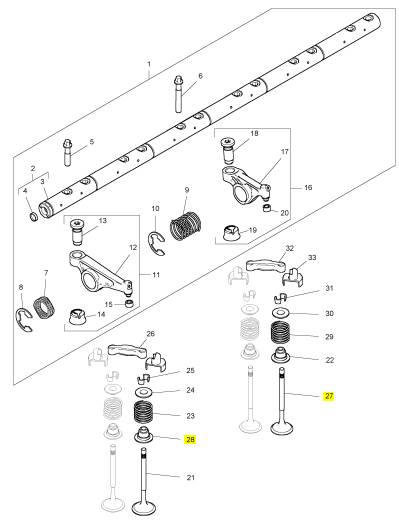
Perkins1206-E70TTA柴油发动机摇臂、T407502气门
详细描述
项目 零配件号码 新件号 描述
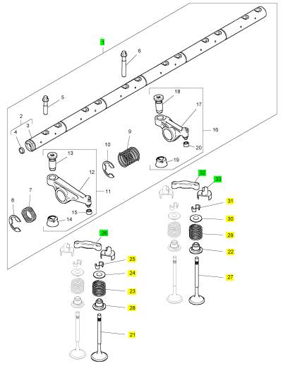
1 T405925 1 T405925 摇臂组合
21 T406777 12 T406777 进气门
22 T412573 12 T412573 气门油封
22 T407967 12 T407967 气门油封
23 T417519 12 T417519 阀弹簧
23 3174 A026 12 T417519 阀弹簧
24 T406809 12 T406809 承件
25 3142 W003 24 3142 W003 阀筒夹
26 T407502 6 T407502 气门
26 T406575 6 T407502 气门
27 T405211 12 T405211 排气阀
28 T412573 12 T412573 气门油封
28 T407967 12 T407967 气门油封
29 T417713 12 T417713 阀弹簧
29 3174 A028 12 T417713 阀弹簧
30 T406809 12 T406809 承件
31 3142 W003 24 3142 W003 阀筒夹
32 T407502 6 T407502 气门
32 T406575 6 T407502 气门
33 T416277 1 T416277 承件
项目 零配件号码 新件号 描述
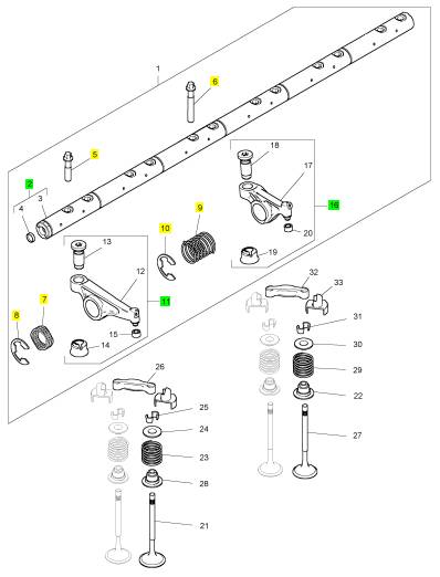
2 T405681 1 T405681 摇臂轴组合
5 T406016 11 T406016 螺拴
6 2316 A901 1 2316 A901 螺旋
7 3174 A024 1 3174 A024 摇臂轴弹簧
8 2727 A015 1 2727 A015 CIRCLIP
9 T407095 5 T407095 摇臂轴弹簧
10 2727 A015 5 2727 A015 CIRCLIP
11 T407570 6 T407570 摇臂组合
16 T406261 6 T406261 摇臂组合
项目 零配件号码 新件号 描述
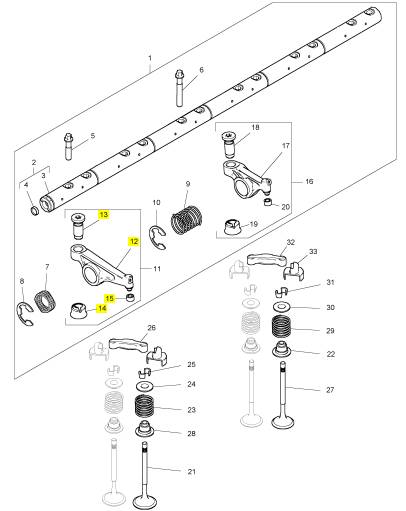
12 1 摇臂
13 T407571 1 T407571 摇臂气门调整
14 T406029 1 T406029 导入
15 1 碗
项目 零配件号码 新件号 描述
17 1 摇臂
18 T407571 1 T407571 摇臂气门调整
19 T406029 1 T406029 导入
20 1 碗
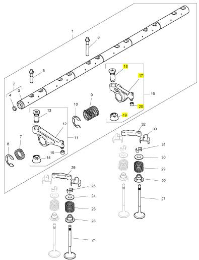
项目 零配件号码 新件号 描述
27 T407502 1 T407502 气门
28 2 承件
35 T407502 1 T407502 气门
36 2 承件
项目 零配件号码 新件号 描述
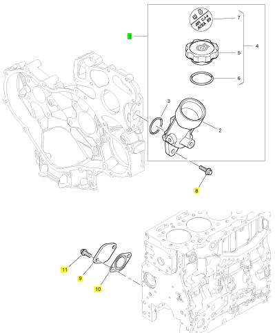
1 T408610 1 T408610 油填隙油
8 2314 H004 2 2314 H004 螺旋
9 T407228 1 T407228 板
10 3683 A022 1 3683 A022 密封垫片
11 2314 H003 2 2314 H003 螺旋
|
Customer Specified Parameters |
|
Throttle Lock Engine Set Speed 1 |
|
Throttle Lock Engine Set Speed Decrement |
|
The “Throttle Lock Engine Set Speed 1” parameter is one of the engine speeds that can be selected in the PTO Set/Resume mode. |
|
The “Throttle Lock Engine Set Speed Decrement” parameter controls the decrease in engine speed when the PTO switch is briefly operated to DECELERATE. If this parameter is set to “0” , the feature is turned off. |
|
Table 50 |
|
Minimum |
|
Maximum |
|
Default |
|
Low idle speed |
|
Rated speed |
|
700 |
|
Table 55 |
|
Minimum |
|
Maximum |
|
Default |
|
Throttle Lock Engine Set Speed 2 |
|
0 rpm |
|
200 rpm |
|
10 rpm |
|
The “Throttle Lock Engine Set Speed 1” parameter is one of the engine speeds that can be selected in the PTO Set/Resume mode. |
|
Miscellaneous |
|
Table 51 |
|
Monitoring Mode Shutdowns |
|
Minimum |
|
Maximum |
|
Default |
|
The “Monitoring Mode Shutdowns” parameter controls the shutdown feature that is associated with the engine monitoring feature. When this feature is enabled and a diagnostic code with a “-31” suffix is detected, the engine will be shut down. |
|
Low idle speed |
|
Rated speed |
|
700 |
|
Throttle Lock Increment Speed Ramp Rate |
|
Table 56 |
|
Value |
|
Default |
|
The “Throttle Lock Increment Speed Ramp Rate” parameter is the rate of engine acceleration when the PTO switch is held in the ACCELERATE position. If this parameter is set to “0” , the feature is turned off. |
|
Disabled Enabled |
|
Enabled |
|
Table 52 |
|
Monitoring Mode Derates |
|
Minimum |
|
Maximum |
|
Default |
|
The “Monitoring Mode Derates” parameter controls the amount of derate that is associated with the engine monitoring feature. When this feature is enabled and a diagnostic code with an appropriate FMI is detected, the engine will be derated. |
|
0 rpm/sec |
|
600 rpm/sec |
|
400 rpm/sec |
|
Throttle Lock Decrement Speed Ramp Rate |
|
Table 57 |
|
The “Throttle Lock Decrement Speed Ramp Rate” parameter is the rate of engine deceleration when the PTO switch is held in the DECELERATE position. If this parameter is set to “0” , the feature is turned off. |
|
Value |
|
Default |
|
Disabled Enabled |
|
Enabled |
|
Table 53 |
|
Limp Home Desired Engine Speed |
|
Minimum |
|
Maximum |
|
Default |
|
0 rpm/sec |
|
600 rpm/sec |
|
400 rpm/sec |
|
The “Limp Home Desired Engine Speed” parameter is the maximum speed of the engine when the engine has been derated. |
|
Throttle Lock Engine Set Speed Increment |
|
Table 58 |
|
Minimum |
|
Maximum |
|
Default |
|
700 rpm |
|
1800 rpm |
|
1200 rpm |
|
The “Throttle Lock Engine Set Speed Increment” parameter controls the increase in engine speed when the PTO switch is briefly operated to ACCELERATE. If this parameter is set to “0” , the feature is turned off. |
|
Engine Acceleration Rate |
|
The “Engine Acceleration Rate” parameter is the acceleration rate for the engine under normal operating conditions. A setting of “0” disables this function. |
|
Table 54 |
|
Minimum |
|
Maximum |
|
Default |
|
0 rpm |
|
200 rpm |
|
10 rpm |
|
Table 59 |
|
Minimum |
|
Maximum |
|
Default |
|
0 rpm |
|
65503 rpm/sec |
|
0 rpm/sec |
|
This document is printed from SPI². Not for RESALE |
![]()
![]()
![]()
![]()
![]()
![]()
![]()
![]()
![]()
![]()
|
KENR9101 |
|
45 |
|
Customer Specified Parameters |
|
Engine Speed Decelerating Ramp Rate |
|
Cooling Fan Temperatures |
|
The “Engine Speed Decelerating Ramp Rate” parameter is the deceleration ramp rate for the engine under normal operating conditions. A setting of “0” disables this function. |
|
Table 63 |
|
Parameter |
|
Value |
|
Default |
|
Charge Air Cooler Outlet Temperature Input Enable |
|
Enabled Disabled |
|
Table 60 |
|
Enabled |
|
Minimum |
|
Maximum |
|
Default |
|
Maximum Air Flow Charge Air Cooler Outlet Temperature |
|
0 rpm |
|
65503 rpm/sec |
|
0 rpm/sec |
|
Degrees C Degrees C |
|
45 Degrees C 40 Degrees C |
|
Intermediate Engine Speed |
|
Minimum Air Flow Charge Air Cooler Outlet Temperature |
|
The “Intermediate Engine Speed” is a selectable engine speed that is between the low idle speed and the high engine speed. This parameter is disabled when the value is set to 0 rpm. |
|
Coolant Temperature Input Enable Status |
|
Enabled Disabled |
|
Enabled |
|
Maximum Air Flow Coolant Temperature |
|
Table 61 |
|
Degrees C Degrees C |
|
102 Degrees C 92 Degrees C |
|
Minimum |
|
Maximum |
|
Default |
|
Minimum Air Flow Coolant Temperature |
|
0 rpm |
|
2800 rpm |
|
0 rpm |
|
Transmission Oil Temperature Input Enable Status |
|
Enabled Disabled |
|
Engine Fan Control |
|
Enabled |
|
Table 62 |
|
Maximum Air Flow Transmission Oil Temperature |
|
Degrees C Degrees C |
|
110 Degrees C |
|
Parameter |
|
Value |
|
Default |
|
Off On |
|
Engine Fan Control |
|
Off |
|
Minimum Air Flow Transmission Oil Temperature |
|
100 Degrees C |
|
Engine Fan Type Configuration |
|
Viscous Clutch Variable Hydraulic |
|
Variable Hydraulic 1.2:1 |
|
Hydraulic Oil Tem- perature Input Ena- ble Status |
|
Enabled Disabled |
|
Pulley Ratio |
|
Ratio |
|
Enabled |
|
Temperature Error Increasing Hysteresis |
|
Percentage |
|
10% |
|
Maximum Air Flow Hydraulic Oil Temperature |
|
Degrees C Degrees C |
|
110 Degrees C |
|
Temperature Error Decreasing Hysteresis |
|
Percentage |
|
10% |
|
Minimum Air Flow Hydraulic Oil |
|
100 Degrees C |
|
Temperature |
|
Current Ramp Rate Fan Speed |
|
Amps per Second Percentage RPM |
|
0.1 amps/sec |
|
Auxiliary #1 Temper- ature Input Enable Status |
|
Enabled Disabled |
|
100% |
|
Enabled |
|
Top Fan Speed |
|
1600 rpm |
|
Maximum Air Flow Auxiliary #1 Temperature |
|
Minimum Desired Fan Speed |
|
500 rpm 0.3 Amps 1.5 Amps |
|
Degrees C Degrees C |
|
110 Degrees C |
|
RPM Amps Amps |
|
Solenoid Minimum Current |
|
Minimum Air Flow Auxiliary #1 Temperature |
|
100 Degrees C |
|
Solenoid Maximum Current |
|
Auxiliary #2 Temper- ature Input Enable Status |
|
Enabled Disabled |
|
Solenoid Dither Frequency |
|
Enabled |
|
Hz |
|
100 Hz |
|
Maximum Air Flow Auxiliary #2 Temperature |
|
Solenoid Dither Amplitude |
|
Amps |
|
0.1 Amps |
|
Degrees C |
|
110 Degrees C |
|
Minimum Air Flow Auxiliary #2 |
|
Degrees C |
|
100 Degrees C |
|
Temperature |
|
This document is printed from SPI². Not for RESALE |
![]()
![]()


![]()
|
46 |
|
KENR9101 |
|
Customer Specified Parameters |
|
Fan Reversing |
|
Table 67 |
|
Value |
|
Default |
|
Table 64 |
|
Normally Open Normally Closed |
|
Parameter |
|
Value |
|
Default |
|
Normally Open |
|
Enabled Disabled |
|
Reversing Feature |
|
Disabled |
|
Water in Fuel Switch InstallationStatus |
|
Reverse Operation Early Termination Enable Status |
|
Enabled Disabled |
|
Disabled Disabled |
|
Programming the “Water in Fuel Switch Installation Status” parameter to “Enabled” notifies the ECM that a water-in-fuel switch input is present. When this parameter is programmed to “Enabled” and the water-in-fuel switch closes, a 97-17 diagnostic code will be displayed. |
|
Enabled Disabled |
|
Manual Purge |
|
Enabled Disabled |
|
Suspend Purge |
|
Disabled 3600 Seconds 30 Seconds |
|
Table 68 |
|
Purge Cycle Interval |
|
Seconds Seconds |
|
Value |
|
Default |
|
Purge Cycle Duration |
|
Installed Not Installed |
|
Not Installed |
|
ConfigurableInputs |
|
User-Defined Switch InstallationStatus |
|
Coolant Level Switch |
|
A user-defined shutdown switch is an optional switch input. Programming the “User Defined Switch Installation Status” parameter to “Enabled” notifies the ECM that a user-defined switch input is present. If this parameter is programmed to “Enabled” and the user-defined shutdown switch closes, the engine will shut down. |
|
A coolant level sensor is an optional switch input. Programming the “Coolant Level Switch” parameter to “Enabled” notifies the ECM that a coolant level switch input is present. If this parameter is programmed to “Enabled” and the coolant level falls below the measured level, a “111-1” diagnostic code will be displayed. |
|
Table 69 |
|
Value |
|
Default |
|
Table 65 |
|
Value |
|
Default |
|
Installed Not Installed |
|
Not Installed |
|
Installed Not Installed |
|
Not Installed |
|
Auxiliary Temperature Sensor Installation Status |
|
Air Filter Restriction Switch Installation Status |
|
An auxiliary temperature sensor is an optional input. Programming the “Auxiliary Temperature Sensor Installation Status” parameter to “Enabled” notifies the ECM that an auxiliary temperature sensor input is present. |
|
An “Air Filter Restriction Switch” is an optional switch input. Programming the “Air Filter Restriction Switch Installation Status” parameter to “Enabled” notifies the ECM that an input from the air filter restriction switch is present. When this parameter is programmed to “Enabled” and the air filter restriction switch closes, a 107-15 diagnostic code will be displayed. |
|
Table 70 |
|
Value |
|
Default |
|
Installed Not Installed |
|
Not Installed |
|
Table 66 |
|
Value |
|
Default |
|
Auxiliary Pressure Sensor Installation Status |
|
Installed Not Installed |
|
Not Installed |
|
An auxiliary pressure sensor is an optional input. Programming the “Auxiliary Pressure Sensor Installation Status” parameter to “Enabled” notifies the ECM that an auxiliary pressure sensor input is present. |
|
Air Filter Restriction Switch Configuration |
|
If an “Air Filter Restriction Switch” is installed, this parameter identifies the type of switch that is installed. |
|
This document is printed from SPI². Not for RESALE |

![]()
|
KENR9101 |
|
47 |
|
Customer Specified Parameters |
|
Table 71 |
|
Diesel Particulate Filter Soot Loading Indicator Installation |
|
Value |
|
Default |
|
Installed Not Installed |
|
A diesel particulate filter soot loading indicator is an optional indicator. Programming the “Diesel Particulate Filter Soot Loading Indicator Installation” parameter to “Installed” notifies the ECM that a diesel particulate filter soot loading indicator is present. If this parameter is set to “Not Installed” , the system defaults to J1939 control. |
|
Not Installed |
|
Fuel Filter Differential Pressure Switch Configuration |
|
A fuel filter differential pressure switch is an optional input. Programming the switch configuration parameter to “Normally Open” or “Normally Closed” notifies the ECM that a fuel filter differential pressure switch input is present. |
|
Table 75 |
|
Value |
|
Default |
|
Installed Not Installed |
|
Not Installed |
|
Table 72 |
|
Value |
|
Default |
|
Regeneration Active Indicator Installation |
|
Not Installed Normally Open Normally Closed |
|
A Regeneration Active Indicator is an optional indicator. Programming the “Regeneration Active Indicator Installation” parameter to “Installed” notifies the ECM that a Regeneration Active indicator is present. If this parameter is set to “Not Installed” , the system defaults to J1939 control. |
|
Not Installed |
|
Diesel Particulate Filter Regeneration Force/InhibitSwitch Installation |
|
Table 76 |
|
A diesel particulate filter regeneration force/inhibit switch is an optional switch input. Programming the “Diesel Particulate Filter Regeneration Force/Inhibit Switch Installation” parameter to “Installed” notifies the ECM that a diesel particulate filter regeneration force/inhibit switch is present. If this parameter is set to “Not Installed” , the system defaults to J1939 control. |
|
Value |
|
Default |
|
Installed Not Installed |
|
Not Installed |
|
J1939 Continuous Fault Handling |
|
Remote Torque Speed Control Enable Status |
|
Table 73 |
|
Value |
|
Default |
|
Installed Not Installed |
|
The Remote Torque Speed Control Enable Status parameter controls the type of remote TSC input. If this parameter is “Enabled” , the ECM expects a continuous signal from TSC1. If this parameter is “Disabled” , the ECM expects an intermittent signal from TSC1. |
|
Not Installed |
|
Diesel Particulate Filter Regeneration Inhibit Indicator Installation |
|
Table 77 |
|
A diesel particulate filter regeneration inhibit indicator is an optional indicator. Programming the “Diesel Particulate Filter Regeneration Inhibit Indicator Installation” parameter to “Installed” notifies the ECM that a diesel particulate filter regeneration inhibit indicator is present. If this parameter is set to “Not Installed” , the system defaults to J1939 control. |
|
Value |
|
Default |
|
Enabled Disabled |
|
Disabled |
|
System Settings |
|
Table 74 |
|
System Operating Voltage Configuration |
|
Value |
|
Default |
|
Installed Not Installed |
|
The System Operating Voltage Configuration parameter is the operating voltage for the engine electrical system. |
|
Not Installed |
|
Table 78 |
|
Value |
|
Default |
|
12 VDC 24 VDC |
|
24 VDC |
|
This document is printed from SPI². Not for RESALE |
![]()
|
48 |
|
KENR9101 |
|
Customer Specified Parameters |
|
Passwords |
|
Customer Password 1 |
|
The Customer Password 1 is the first security password that can be defined by the customer. |
|
Table 79 |
|
Value |
|
Default |
|
Eight alphanumeric characters |
|
Eight spaces |
|
Customer Password 2 |
|
The Customer Password 2 is the second security password that can be defined by the customer. |
|
Table 80 |
|
Value |
|
Default |
|
Eight alphanumeric characters |
|
Eight spaces |
|
Security Access Parameters |
|
CAN Communication Protocol Write Security |
|
The CAN Communication Protocol Write Security parameter control the security required for writing information through the CAN bus. |
|
Table 81 |
|
Value |
|
Default |
|
Seed and Key No Security |
|
Seed and Key |
|
CAN Communication Protocol Read Security |
|
The CAN Communication Protocol Read Security parameter control the security required for reading information from the CAN bus. |
|
Table 82 |
|
Value |
|
Default |
|
Seed and Key No Security |
|
Seed and Key |
|
This document is printed from SPI². Not for RESALE |
![]()
![]()
![]()
|
KENR9101 |
|
49 |
|
Customer Specified Parameters |
|
i04805686 |
|
Customer Specified Parameters Table |
|
This document is printed from SPI². Not for RESALE |
![]()
|
50 |
|
KENR9101 |
|
Customer Specified Parameters |
|
Table 83 |
|
Customer Specified Parameters Possible Values |
|
ECM Parameter ECM Identification Parameter Equipment ID |
|
Default Value |
|
17 Digits Available characters are dependent on the service tool that is used |
|
Not Programmed |
|
Engine Rating Parameter Rating Number |
|
1 to 4 |
|
1 |
|
Speed Control |
|
Low Idle Speed |
|
700 to 1200 rpm |
|
750 rpm |
|
Engine Configuration Parameter Ether Solenoid Configuration |
|
Not Installed |
|
Not Installed |
|
Continuous Flow Solenoid |
|
Engine Idle Shutdown |
|
Minimum Ambient Air Temperature Maximum Ambient Air Temperature Shutdown Enable Status |
|
0 to 29 degrees C |
|
0 degrees C 30 degrees C Disabled |
|
30 to 100 degrees C |
|
Disabled Enabled |
|
Shutdown Delay Time |
|
1 to 60 minutes |
|
5 minutes Disabled |
|
Ambient Temperature Override Enable Status |
|
Disabled Enabled |
|
Air Shutoff |
|
Air Shutoff |
|
Disabled Enabled |
|
Enabled Enabled |
|
Aftertreatment Configuration |
|
ARD Auto Regeneration Enable Status |
|
Disabled Enabled |
|
DPF #1 Soot Loading Sensing System Configuration Code High Soot Load Aftertreatment Protection |
|
20(Hex) to 7F(Hex) |
|
0 |
|
Disabled Enabled |
|
Disabled |
|
Multiple Engines on J1939 |
|
Engine Location |
|
Engine #1 Engine #2 Engine #3 Engine #4 Engine #5 |
|
Engine #1 |
|
PTO and Throttle Lock Parameters |
|
Throttle Lock Feature Installation Status |
|
Installed Not Installed |
|
Not Installed Set/Resume |
|
PTO Mode |
|
Ramp Up/Ramp Down Set/Resume |
|
Throttle Lock Engine Set Speed 1 Throttle Lock Engine Set Speed 2 Throttle Lock Increment Speed Ramp Rate |
|
Low idle speed to rated speed Low idle speed to rated speed 0 to 600 rpm/sec |
|
700 rpm 700 rpm |
|
400 rpm/sec |
|
(continued) |
|
This document is printed from SPI². Not for RESALE |