 English
 Espaol
 Franais
 阿拉伯
阿拉伯 中文
中文 Deutsch
 Italiano
 Português
 日本
日本 韩国
韩国 български
 hrvatski
 esky
esky Dansk
Dansk Nederlands
 suomi
suomi Ελληνικ
 印度
印度 norsk
norsk Polski
 Roman
Roman русский
 Svenska
Perkins1206-E70TTA柴油发动机T410145燃油喷射泵供应商,Perkins1206-E70TTA柴油发动机T410145燃油喷射泵技术价格规格咨询服务,Perkins1206-E70TTA柴油发动机T410145燃油喷射泵零配件供应,Perkins1206-E70TTA柴油发动机T410145燃油喷射泵售后服务中心,Perkins1206-E70TTA柴油发动机T410145燃油喷射泵,Perkins1206-E70TTA柴油发动机T410145燃油喷射泵详细的技术参数,

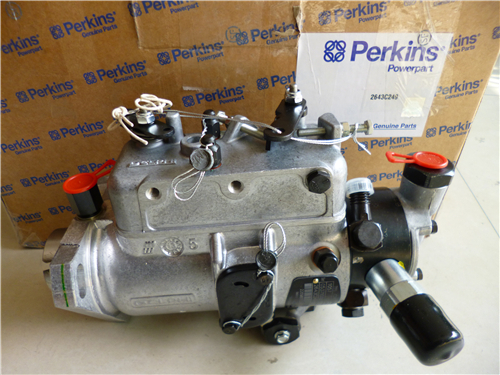
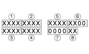
Perkins1206-E70TTA柴油发动机T410145燃油喷射泵
详细描述
项目 零配件号码 新件号 描述
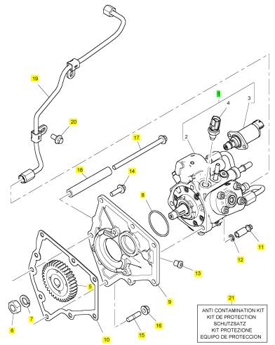
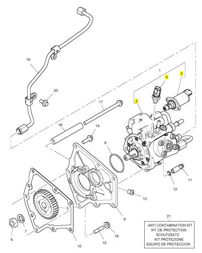
1 T410145 1 T410145 燃油喷射泵
5 T406023 1 T406023 燃油喷射泵传动机构
6 2318 A108 1 2318 A108 螺帽
7 K134AF01 1 K134AF01 垫圈
8 T405938 1 T405938 密封O型圈
9 T407049 1 T407049 板
10 T406721 1 T406721 密封垫片 - 燃油的 INJ 泵
11 2316 A317 3 2316 A317 螺旋
12 2134 A008 3 2134 A008 垫圈
13 2487 A208 1 2487 A208 栓塞
14 2314 H034 4 2314 H034 螺旋
15 2313 M058 2 2313 M058 图钉
16 2318 A603 2 2318 A603 螺帽
17 2314 H022 1 2314 H022 螺旋
18 T406074 1 T406074 间隔器
19 T406115 1 T406115 加燃油管 - 燃油泵加燃油轨条
20 2314 H003 1 2314 H003 螺旋
21 T410437 1 T410437 保护装备
项目 零配件号码 新件号 描述
2 1 燃油喷射泵
3 T408507 1 T408507 阀
4 T405451 1 T405451 温度感应传感器
|
“WinFlash” Error Messages |
|
If any error messages are displayed during flash programming, click on the “Cancel” button in order to stop the process. Access the information about the “ECM Summary” under the “Information” menu. Ensure that you are programming the correct flash file for your engine. |
|
If a 630-2 diagnostic trouble code is displayed after flash programming, a required parameter is missing. Program the missing parameter. |
|
i05085410 |
|
Injector Code - Calibrate |
|
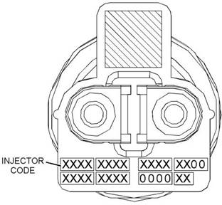
Illustration 21 |
|
g02132457 |
|
Sequence for recording the injector code |
|
Injector codes are codes that are 30 hexadecimal characters in length that are supplied with each injector. The code is on a plate on the top of the injector and a card is also included in the packaging for the injector. The code is used by the Electronic Control Module (ECM) to balance the performance of the injectors. |
|
The electronic service tool is used to load the injector codes into the ECM. |
|
The injector codes must be loaded into the ECM if any of the following conditions occur: |
|
• An electronic unit injector is replaced. • The ECM is replaced. |
|
• Diagnostic code 630-2 is active. |
|
• Electronic unit injectors are exchanged between cylinders. |
|
Note: Diagnostic code 630-2 will also become active if the engine serial number, FLS or FTS are not entered into the ECM. |
|
If the ECM is replaced, the injector codes are normally transferred to the new ECM as part of the “Copy Configuration” procedure. If the “Copy Configuration” procedure fails, the injector codes must be loaded manually. |
|
Installing Injector Codes |
|
Note: The injector code is located on the electronic unit injector. |
|
1. Record the injector code for each electronic unit injector. |
|
Illustration 20 |
|
g02854936 |
|
Label with the injector code |
|
2. Connect the electronic service tool to the diagnostic connector. Refer to Troubleshooting, “Electronic Service Tools”. |
|
3. Turn the keyswitch to the ON position. |
|
4. Select the following menu options on the electronic service tool: |
|
• Service |
|
• Calibrations |
|
• Injector Trim Calibration |
|
This document is printed from SPI². Not for RESALE |
![]()
![]()
![]()
![]()
![]()
|
KENR9101 |
|
37 |
|
Programming Parameters |
|
5. Select the appropriate cylinder. 6. Click on the “Change” button. |
|
Mode Selection Switch Input 2 and Mode Selection Switch Input 1 |
|
The number of these non-programmable parameters that are visible depends on the value that is programmed into the “Number of Switch Inputs” parameter. “Open” signifies that the switch is in the OFF position. “Ground” signifies that the switch is in the ON position. |
|
7. Input the applicable injector code that was recorded in Test Step 1. |
|
8. Click on the “OK” button. |
|
The injector code is loaded into the ECM. |
|
Rating Enabled |
|
9. Repeat the procedure for each cylinder, as |
|
required. |
|
If “Yes” is selected on the drop-down menu, the ECM is programmed to use the values that are programmed into “Rating Number” , “Throttle 1 Droop Percentage” , “Throttle 2 Droop Percentage” and “TSC1 Droop Percentage” for the given combination of switch positions. |
|
Exchanging Electronic Unit Injectors |
|
Exchanging electronic unit injectors can help determine if a combustion problem is in the electronic unit injector or in the cylinder. If two electronic unit injectors that are currently installed in the engine are exchanged between cylinders, the injector codes must also be exchanged. Press the “Exchange” button at the bottom of the “Injector Trim Calibration” screen on the electronic service tool. Select the two electronic unit injectors that will be exchanged and press the “OK” button. The tattletale for the electronic unit injectors that were exchanged will increase by one. |
|
Table 8 |
|
Values |
|
Default |
|
Factory Password |
|
Yes No |
|
No |
|
No |
|
High Idle Speed |
|
The “High Idle Speed” is the maximum engine rpm. |
|
i03771589 |
|
Table 9 |
|
Mode Switch Setup |
|
Minimum |
|
Maximum |
|
Default |
|
1800 rpm |
|
2800 rpm |
|
2420 rpm |
|
The Mode Switches can be used to change the performance characteristics of the engine. The electronic service tool is used to program the characteristics. Select the “Service” drop-down menu and then select “Engine Operating Mode Configuration” . A maximum of two switches can be used. “Switch 1” is connected to J1:62Mode Switch 1. “Switch 2” is connected to J1:64Mode Switch 2. The other contact on both switches is connected to J1:18Switch Return. |
|
Rating Number |
|
This parameter is the engine rating that is used by the Electronic Control Module (ECM) for a given combination of switch positions. There is a maximum of four ratings in a flash file. |
|
Table 10 |
|
Range |
|
Default |
|
Factory Password |
|
Number of Switch Inputs |
|
1 to the maximum number of ratings in the currently installed Flash File |
|
1 |
|
No |
|
This configuration parameter is the total number of switches that are used. The switches can be individual switches or a multiple rotary switch. |
|
Table 7 |
|
Rated Speed (RPM) |
|
Range |
|
Default |
|
This parameter represents the engine speed that is selected when the mode switch or the mode switches are in a particular position. |
|
0 to 2 |
|
0 |
|
Mode Selection Number |
|
Table 11 |
|
Range |
|
Default |
|
Factory Password |
|
This parameter is a non-programmable parameter that represents the number of possible combinations of switch positions. This parameter is based on the value that is programmed into the “Number of Switch Inputs” parameter. |
|
“Programmed Low Idle” to “Pro- grammed High Idle” |
|
2100 rpm |
|
No |
|
This document is printed from SPI². Not for RESALE |
![]()
![]()
![]()
|
38 |
|
KENR9101 |
|
Programming Parameters |
|
Engine High Idle Speed (RPM) |
|
i04105410 |
|
Throttle Setup |
|
This parameter represents a maximum of 112% of the rated speed that is selected when the mode switch or the mode switches are in a particular position. |
|
Table 12 |
|
There are two separate channels for throttle input. The two channels can have any combination of a digital throttle that uses a Pulse Width Modulated (PWM) signal, an analog throttle or a multi-position switched throttle. |
|
Range |
|
Default |
|
Factory Password |
|
“1800 to 2800 rpm” 112% of rated speed |
|
No |
|
The Electronic Control Module (ECM) must be programmed with the type of throttle input that is being used in either position. From the menu, select “Services” . On the “Services” screen, select “Throttle Configuration” . Select the type of throttle from the following list: |
|
Governor Type |
|
This parameter represents the mode of operation of the governor that is installed on the engine. |
|
Table 13 |
|
Range |
|
Default |
|
Factory |
|
• No throttle |
|
Password |
|
• Analog throttle |
|
“Min/Max speed (rpm)” or “All Speed” |
|
All Speed |
|
No |
|
• PWM throttle |
|
• Multi-position throttle switch |
|
Throttle 1 Droop Percentage |
|
The Electronic Control Module (ECM) must be programmed for throttle arbitration. This parameter determines which throttle input has priority. From the menu, select “Services” . On the “Services” screen, select “Throttle Arbitration” . Select the arbitration method from the following list: |
|
This parameter represents the amount of droop that is applied to the “Throttle 1” input. |
|
Table 14 |
|
Range |
|
Default |
|
Factory Password |
|
• Highest Wins • Lowest Wins • Manual Switch |
|
0 to 10 percent |
|
5.0% |
|
No |
|
Throttle 2 Droop Percentage |
|
The default setting for throttle arbitration is “Highest Wins” . |
|
This parameter represents the amount of droop that |
|
is applied to the “Throttle 2” input. |
|
Table 15 |
|
Range |
|
Default |
|
Factory |
|
Password |
|
0 to 10 percent |
|
5.0% |
|
No |
|
TSC1 Droop Percentage |
|
This parameter represents the amount of droop that is applied to the “Torque Speed Control 1(TSC1)” input. |
|
Table 16 |
|
Range |
|
Default |
|
Factory |
|
Password |
|
0 to 10 percent |
|
5.0% |
|
No |
|
This document is printed from SPI². Not for RESALE |

![]()
|
KENR9101 |
|
39 |
|
Programming Parameters |
|
Table 18 |
|
Range |
|
Default |
|
0 to 100% |
|
10% |
|
Initial Lower Position Limit |
|
This parameter is the maximum throttle percentage that will be interpreted by the ECM as zero throttle. This parameter is used with the value of the lower position limit to make an allowance for manufacturing tolerances between different pedals. |
|
Table 19 |
|
Range |
|
Default |
|
0 to 100% |
|
20% |
|
Idle Validation |
|
All analog throttles and digital throttles can have an idle validation switch. If this parameter is programmed to “Yes” , the ECM will look for this switch input on pin J1:22 for Idle Validation Switch 1 (IVS1) and J1:40 for Idle Validation Switch 2 (IVS2). |
|
Illustration 22 |
|
g01785156 |
|
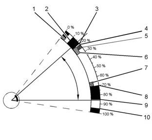
Typical Range of Throttle |
|
(1) Lower Diagnostic Limit (Default=5) (2) Lower Position Limit (Default=10) (3) Initial Lower Position (Default=20) (4) Idle Validation Minimum Off Threshold (Default=21) (5) Idle Validation Maximum On Threshold (Default=25) (6) Lower Dead Zone % (Default=8) |
|
Table 20 |
|
Values |
|
Default |
|
No Yes |
|
No |
|
(7) Upper Dead Zone % (Default=5) |
|
(8) Initial Upper Position (Default=70) (9) Upper Position Limit (Default=85) |
|
(10) Upper Diagnostic Limit (Default=95) |
|
Idle Validation Minimum Off (Open) Threshold |
|
Analog throttles and digital throttles require additional programming. If a multi-position switch is selected, additional parameters must be programmed. Refer to the Troubleshooting Guide, “Multiposition Switch Setup”. If an analog throttle or a digital throttle is selected, the following parameters can be |
|
This parameter is the minimum throttle percentage that will be detected by the ECM when the IVS is ON (Closed). |
|
If the ECM detects a throttle percentage below this value with the idle validation switch OFF (Open), a fault code will be generated and the engine will remain at idle. |
|
programmed into the ECM. |
|
Lower Diagnostic Limit |
|
This parameter is the minimum throttle percentage that should be detected by the ECM in normal operation when the pedal is in the “off” position. A value below this limit will generate a short circuit diagnostic code. The range of this diagnostic detection area is from 0 percent to the programmed value for the lower position limit. |
|
Refer to Table 21 and Table 22 . |
|
Table 17 |
|
Range |
|
Default |
|
0 to 100% |
|
5% |
|
Lower Position Limit |
|
This parameter is the minimum throttle percentage that will be interpreted by the ECM as zero throttle. This parameter is used with the value of initial lower position limit to make an allowance for manufacturing tolerances between different pedals. |
|
This document is printed from SPI². Not for RESALE |
![]()
![]()
![]()
![]()
![]()
![]()
|
40 |
|
KENR9101 |
|
Programming Parameters |
|
Table 21 |
|
Throttle Position Sensor Idle Validation Switch (IVS) Throttle Demand Output (TPS) |
|
Fault Status |
|
Comment |
|
TPS< IVS Min OFF TPS< IVS Min OFF |
|
OFF ON |
|
Minimum Position Throttle Position |
|
Raise IVS fault No fault |
|
Force throttle demand to minimum |
|
Normal operation |
|
Table 22 |
|
Range |
|
Default |
|
0 to 100% |
|
21% |
|
Idle Validation Maximum On (Closed) Threshold |
|
This parameter is the maximum throttle percentage that will be detected by the ECM when the idle validation switch (IVS) is OFF (Open) . When the idle validation switch is OFF (Open) and the ECM detects a signal that is higher than the programmed value for IVS Max ON , the ECM will generate a fault code and the engine will remain at idle. |
|
Refer to Table 23 and Table 24 . Table 23 |
|
Throttle Position Sensor Idle Validation Switch (IVS) Throttle Demand Output (TPS) |
|
Fault Status |
|
Comment |
|
TPS> IVS Max ON TPS< IVS Min Off |
|
OFF ON |
|
Throttle Position Minimum Position |
|
No fault |
|
Normal operation |
|
Raise IVS fault |
|
Force throttle demand to minimum |
|
Table 24 |
|
Initial Upper Position Limit |
|
Range |
|
Default |
|
This parameter is the minimum throttle percentage that will be interpreted by the ECM as full throttle. This parameter is used with the value of the upper position limit to make an allowance for manufacturing tolerances between different pedals. |
|
0 to 100% |
|
25% |
|
Lower Dead Zone |
|
Table 27 |
|
This parameter is a throttle range above the initial lower position limit before the engine will increase in rpm. |
|
Range |
|
Default |
|
0 to 100% |
|
70% |
|
Table 25 |
|
Range |
|
Default |
|
Upper Position Limit |
|
0 to 100% |
|
5% |
|
This parameter is the maximum throttle percentage that will be interpreted by the ECM as full throttle. This parameter is used with the value of the initial upper position limit to make an allowance for |
|
Upper Dead Zone |
|
This parameter is a throttle range that is below the initial upper position limit that does not allow the engine speed to increase. |
|
manufacturing tolerances between different pedals. |
|
Table 28 |
|
Range |
|
Default |
|
Table 26 |
|
0 to 100% |
|
85% |
|
Range |
|
Default |
|
0 to 100% |
|
5% |
|
This document is printed from SPI². Not for RESALE |
![]()
![]()
![]()
![]()
![]()
![]()
![]()
|
KENR9101 |
|
41 |
|
Programming Parameters |
|
Upper Diagnostic Limit |
|
Physical Position Enabled |
|
This parameter is the minimum throttle percentage that is detected by the ECM in normal operation when the pedal is in the maximum position. A value above this limit will generate an open circuit diagnostic code. The range of this diagnostic detection area is from the programmed value of the upper position limit to 100 percent. |
|
If “Yes” is selected from the drop-down menu, the ECM sets the engine rpm to the value that is programmed into the “Engine Speed” for the configuration of the switches that is defined for that Physical Position. |
|
Table 31 |
|
Value |
|
Default |
|
Table 29 |
|
No Yes |
|
No |
|
Range |
|
Default |
|
0 to 100% |
|
95% |
|
Logical Position |
|
i04105411 |
|
The Logical Position is the order that is required by the user for a unique Physical Position. |
|
Multiposition Switch Setup |
|
Table 32 |
|
Range with Four Switches |
|
Default |
|
Note: The multi-position throttle switch can only be enabled if the optional PTO switches are not installed. |
|
1 to 16 |
|
1 |
|
The multi-position throttle switch is an optional throttle input. A maximum of four switches can be used. Four switches will allow a maximum of 16 speeds to be selected. |
|
Engine Speed (in RPM) |
|
The “Engine Speed” is the programmed engine rpm for a particular position of the multi-position throttle switch. |
|
If an optional intermediate engine speed switch is installed, the multi-position throttle switch can have a maximum of three switches. Three switches will allow a maximum of eight speeds to be selected. |
|
If the ECM detects a switch combination that has been configured as “No” , a fault code will be generated. In this situation, the ECM will ignore the multi-position switch until the keyswitch is cycled through OFF and ON. |
|
When the multi-position switch is selected as the “Throttle Type” on the “Throttle Configuration Screen” of the electronic service tool, additional information is required. |
|
Table 33 |
|
Range |
|
Default |
|
Number of Switch Inputs |
|
Programmed Low Idle to Pro- grammed High Idle |
|
0 |
|
This parameter is the total number of switches that will be used. The switches may be individual switches or a ganged rotary switch. |
|
Table 30 |
|
Range |
|
Default |
|
1 to 4 |
|
0 |
|
Physical Position |
|
This parameter is non-programmable. The parameter is used to signify the position of the rotary switch. |
|
Input 4, Input 3, Input 2, Input 1 |
|
The number of these non-programmable parameters that are visible depends on the value that is programmed into the “Number of Switch Inputs” parameter. “Open” signifies that the switch is in the OFF position. “Ground” signifies that the switch is in the ON position. |
|
This document is printed from SPI². Not for RESALE |
![]()
![]()
![]()

![]()
|
42 |
|
KENR9101 |
|
Customer Specified Parameters |
|
Customer Specified Parameters |
|
Speed Control |
|
Low Idle Speed |
|
The “Low Idle Speed” is the minimum engine rpm. |
|
Table 36 |
|
Minimum |
|
Maximum |
|
Default |
|
i04805671 |
|
700 rpm |
|
1200 rpm |
|
750 rpm |
|
Customer Specified Parameters |
|
Engine ConfigurationParameters |
|
Ether Solenoid Configuration |
|
Customer specified parameters allow the engine to be configured to the exact needs of the application. |
|
The ether solenoid configuration defines the presence of a solenoid for an ether starting aid. Customer passwords are required in order to change this parameter. |
|
Customer parameters may be changed repeatedly as operational requirements change. |
|
The following information is a brief description of the customer specified parameters. The following parameter values are included with the descriptions: |
|
Table 37 |
|
Value |
|
Default |
|
Not Installed Continuous Flow Solenoid |
|
• Minimum • Maximum • Default |
|
Not Installed |
|
Engine Idle Shutdown |
|
The Engine Idle Shutdown parameters define the engine response when the keyswitch is turned to the OFF position. |
|
ECM IdentificationParameter |
|
Equipment ID |
|
Minimum Ambient Air Temperature |
|
“Equipment ID” is the identification of the equipment that is assigned by the customer. The “Equipment ID” is only for reference by the customer. The “Equipment ID” is not required by the Electronic Control Module (ECM). |
|
Table 38 |
|
Value |
|
Default |
|
0 to 29 Degrees C |
|
0 Degrees C |
|
Table 34 |
|
Value |
|
Default |
|
Maximum Ambient Air Temperature |
|
17 digits |
|
The available characters are de- pendent on the service tool that is being used. |
|
Table 39 |
|
Not programmed |
|
Value |
|
Default |
|
30 to 100 Degrees C |
|
30 Degrees C |
|
Engine Rating Parameter |
|
Shutdown Enable Status |
|
Rating Number |
|
Table 40 |
|
The rating number is the selected rating within a power rating family. The flash file defines the power rating family. The flash file can contain one to four ratings. The rating number defines the power rating that is used within the power rating family. |
|
Value |
|
Default |
|
Enabled Disabled |
|
Disabled |
|
Table 35 |
|
Shutdown Delay Time |
|
Minimum |
|
Maximum |
|
Default |
|
Table 41 |
|
1 |
|
4 |
|
1 |
|
Value |
|
Default |
|
1 to 60 minutes |
|
5 minutes |
|
This document is printed from SPI². Not for RESALE |
![]()
![]()
![]()
![]()
![]()
![]()
|
KENR9101 |
|
43 |
|
Customer Specified Parameters |
|
Ambient Temperature Override Enable Status |
|
Multiple Engines on J1939 |
|
Engine Location |
|
Table 42 |
|
In a situation where multiple engines communicate on one J1939 channel, the Engine Location parameter defines the identity of each engine in the set. |
|
Value |
|
Default |
|
Enabled Disabled |
|
Disabled |
|
Table 47 |
|
Value |
|
Default |
|
Air Shutoff |
|
Engine #1 Engine #2 Engine #3 Engine #4 Engine #5 |
|
Air Shutoff |
|
Engine #1 |
|
The Air Shutoff parameter defines whether an air shutoff valve is installed in the air inlet for the engine. |
|
Table 43 |
|
PTO and Throttle Lock Parameters |
|
Value |
|
Default |
|
Enabled Disabled |
|
Throttle Lock Feature InstallationStatus |
|
Disabled |
|
Note: PTO and a multi-position throttle switch cannot |
|
be installed at the same time. |
|
Aftertreatment Configuration |
|
The “Throttle Lock Feature Installation Status” is used to turn on the throttle lock features. When this parameter is changed to “Installed” , the following parameters are active and the parameters can be programmed. |
|
ARD Auto Regeneration Enable Status |
|
The “ARD Auto Regeneration Enable Status” parameter determines whether automatic ARD regeneration is enabled. |
|
• • • |
|
“PTO engine Speed Setting” |
|
Table 44 |
|
“Throttle Lock Increment Speed Ramp Rate” “Throttle Lock Engine Set Speed Increment” |
|
Value |
|
Default |
|
Disabled Enabled |
|
Enabled |
|
Table 48 |
|
Value |
|
Default |
|
DPF #1 Soot Loading Sensing System ConfigurationCode |
|
Not Installed Installed |
|
Not Installed |
|
The “DPF 1 Soot Loading Sensing System Configuration Code” parameter determines the type of diesel particulate filter #1soot loading sensing system . This parameter identifies orientation of soot sensor, and the geometry of the DPF. |
|
PTO Mode |
|
PTO mode can be configured to operate in either Set/ Resume mode or Ramp up/Ramp down mode. Set/ Resume mode allows the engine speed to be controlled by the operator through switch inputs. This mode allows two specific speeds to be set and stored in the ECM. A speed can be selected or the previously selected speed can be resumed. Adjustments in engine speed can then be made via the raise and lower switch inputs. Ramp up/Ramp down mode only allows the engine speed to be raised or lowered via switch inputs at a desired ramp rate. The “Set” and “Resume” functions are disabled. |
|
Table 45 |
|
Value |
|
Default |
|
20(Hex) to 7F(Hex) |
|
0 |
|
High Soot Load AftertreatmentProtection |
|
The “High Soot Load AftertreatmentProtection” parameter determines whether aftertreatment protection is enabled . |
|
Table 49 |
|
Value |
|
Default |
|
Table 46 |
|
Value |
|
Default |
|
Ramp Up/Ramp Down Set/Resume |
|
Set/Resume |
|
Disabled Enabled |
|
Disabled |
|
This document is printed from SPI². Not for RESALE |