 English
 Espaol
 Franais
 阿拉伯
阿拉伯 中文
中文 Deutsch
 Italiano
 Português
 日本
日本 韩国
韩国 български
 hrvatski
 esky
esky Dansk
Dansk Nederlands
 suomi
suomi Ελληνικ
 印度
印度 norsk
norsk Polski
 Roman
Roman русский
 Svenska
Perkins1206-E70TTA柴油发动机4520330燃油过滤器供应商,Perkins1206-E70TTA柴油发动机4520330燃油过滤器技术价格规格咨询服务,Perkins1206-E70TTA柴油发动机4520330燃油过滤器零配件供应,Perkins1206-E70TTA柴油发动机4520330燃油过滤器售后服务中心,Perkins1206-E70TTA柴油发动机4520330燃油过滤器,Perkins1206-E70TTA柴油发动机4520330燃油过滤器详细的技术参数,


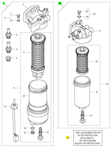
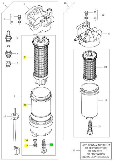
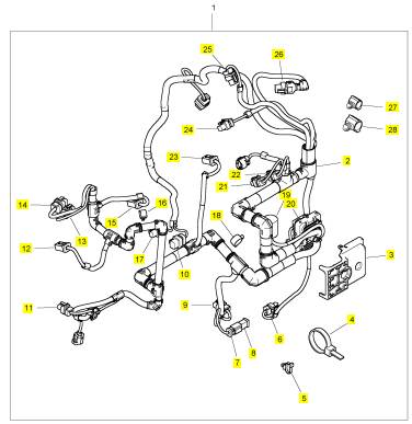
Perkins1206-E70TTA柴油发动机4520330燃油过滤器
详细描述
项目 零配件号码 新件号 描述
1 3593484 1 3593484 燃油过滤器组合
1 3593484 1 3593484 燃油过滤器组合
1 3593484 1 3593484 燃油过滤器组合
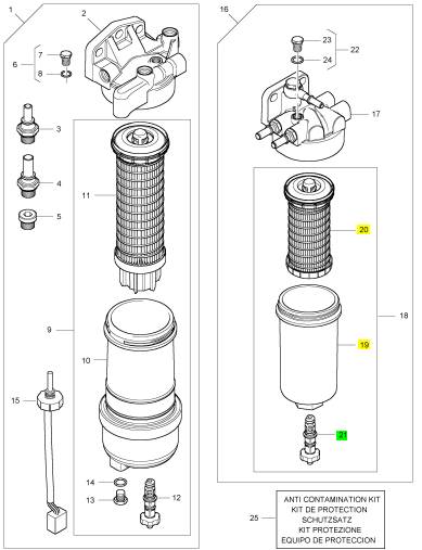
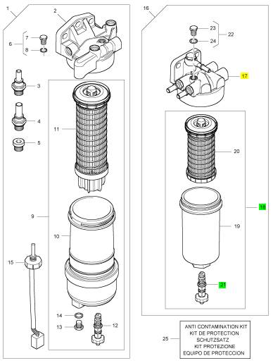
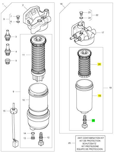
16 4520330 1 4520330 燃油过滤器组合
16 3660645 1 4520330 燃油过滤器组合
25 T410437 1 T410437 保护装备
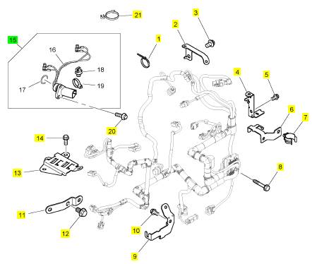
项目 零配件号码 新件号 描述
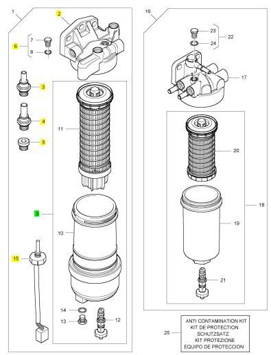
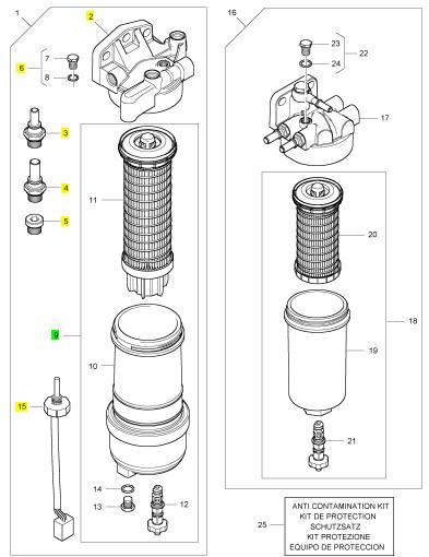
2 1 燃油过滤器座
3 1 连接器
4 1 连接器
5 5 栓塞
6 T410737 1 T410737 栓塞
6 T410730 1 T410730 螺旋
9 3679088 1 3679088 燃油过滤器组合
15 T417241 1 T417241 感应传感器
15 T410761 1 T417241 感应传感器
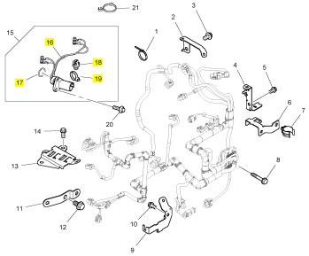
项目 零配件号码 新件号 描述
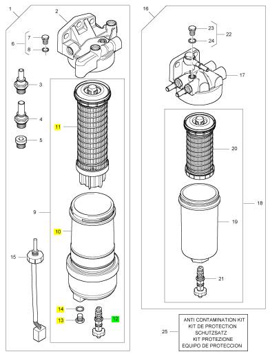
10 1 燃油过滤器体
11 3611273 1 3611273 燃油过滤器
12 T410736 1 T410736 排泄栓塞
13 CH10286 1 CH10286 栓塞
14 CH10046 1 CH10046 密封O型圈
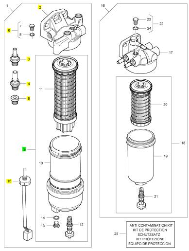
项目 零配件号码 新件号 描述
2 1 燃油过滤器座
3 1 连接器
4 1 连接器
5 5 栓塞
6 T410737 1 T410737 栓塞
6 T410730 1 T410730 螺旋
9 3679088 1 3679088 燃油过滤器组合
15 T417241 1 T417241 感应传感器
15 T410761 1 T417241 感应传感器
项目 零配件号码 新件号 描述
10 1 燃油过滤器体
11 3611273 1 3611273 燃油过滤器
12 T410736 1 T410736 排泄栓塞
13 CH10286 1 CH10286 栓塞
14 CH10046 1 CH10046 密封O型圈
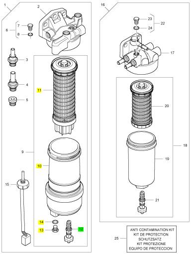
项目 零配件号码 新件号 描述
2 1 燃油过滤器座
3 1 连接器
4 1 连接器
5 5 栓塞
6 T410737 1 T410737 栓塞
6 T410730 1 T410730 螺旋
9 3679088 1 3679088 燃油过滤器组合
15 T417241 1 T417241 感应传感器
15 T410761 1 T417241 感应传感器
项目 零配件号码 新件号 描述
10 1 燃油过滤器体
11 3611273 1 3611273 燃油过滤器
12 T410736 1 T410736 排泄栓塞
13 CH10286 1 CH10286 栓塞
14 CH10046 1 CH10046 密封O型圈
项目 零配件号码 新件号 描述
17 1 燃油过滤器组合
18 3611272 1 3611272 燃油过滤器组合
22 T410737 1 T410737 栓塞
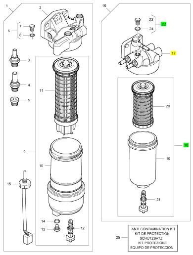
项目 零配件号码 新件号 描述
19 1 燃油过滤器体
20 3611274 1 3611274 燃油过滤器
21 T410736 1 T410736 排泄栓塞
项目 零配件号码 新件号 描述
17 1 燃油过滤器座
18 T410737 1 T410737 栓塞
21 3611272 1 3611272 燃油过滤器组合
项目 零配件号码 新件号 描述
19 1 燃油过滤器体
20 3611274 1 3611274 燃油过滤器
21 T410736 1 T410736 排泄栓塞
项目 零配件号码 新件号 描述
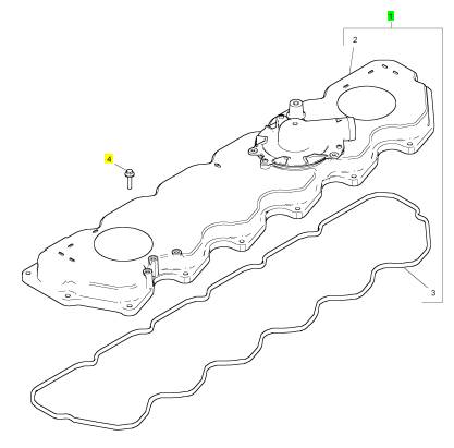
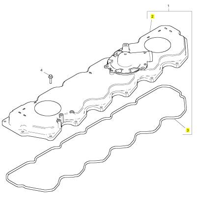
1 T407836 1 T407836 摇臂砂箱盖
4 2314 F006 15 2314 F006 螺旋
项目 零配件号码 新件号 描述
2 1 摇臂砂箱盖
3 T407192 1 T407192 密封 - 摇臂的砂箱盖
项目 零配件号码 新件号 描述
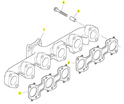
1 T407204 1 T407204 排气岐管
2 T410538 1 T410538 密封垫片 - 排气岐管
3 T410538 1 T410538 密封垫片 - 排气岐管
4 3218 J025 12 3218 J025 螺旋
5 3313 A029 12 3313 A029 间隔器
项目 零配件号码 新件号 描述
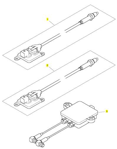
1 T410488 1 T421094 感应传感器
2 T410487 1 T421096 感应传感器
3 T419729 1 T419729 控制砂箱
3 T413563 1 T419729 控制砂箱
项目 零配件号码 新件号 描述
1 T412657 1 T412657 线束
1 T412657 1 T412657 线束
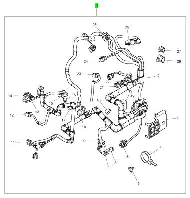
项目 零配件号码 新件号 描述
2 1 线束
3 T413628 1 T413628 盖
4 2817152 7 2817152 缆拉杆
4 7 缆拉杆
5 T409393 22 T409393 缆拉杆
6 28170047 1 28170047 电力连接器
7 28170051 1 28170051 连接器
8 28170055 1 28170055 栓塞
9 T405558 1 T405558 电力连接器
10 T407278 1 T407278 电力连接器
11 28170044 1 28170044 电力连接器
12 28170027 1 28170027 连接器
13 28170046 1 28170046 电力连接器
14 28170097 1 28170097 电力连接器
15 28170027 1 28170027 连接器
16 T400238 1 T400238 接线夹
17 T406317 1 T406317 电力连接器
18 T400239 1 T400239 接线夹
19 T400060 1 T400060 电力连接器
20 T406207 1 T406207 电力连接器
21 28170044 1 28170044 电力连接器
22 T405558 1 T405558 电力连接器
23 28170027 1 28170027 连接器
24 T409319 1 T409319 电力连接器
25 T405558 1 T405558 电力连接器
26 28170029 1 28170029 电力连接器
27 T407702 5 T407702 管夹
28 T410759 3 T410759 接线夹
项目 零配件号码 新件号 描述
1 T406062 3 T406062 缆拉杆
2 T415195 1 T415195 托架
3 2314 J001 1 2314 J001 螺旋
4 T415171 1 T415171 托架
5 2314 H002 1 2314 H002 螺旋
6 T410904 1 T410904 托架
6 T416658 1 T410904 托架
7 2481 D501 1 2481 D501 夹
8 T405657 1 T405657 螺旋
9 T410899 1 T410899 托架
10 2314 H002 1 2314 H002 螺旋
11 T407100 1 T407100 托架
12 2314 H001 1 2314 H001 螺旋
13 T411357 1 T411357 托架
14 2314 F003 3 2314 F003 螺旋
15 T409623 3 T409623 线束
20 T409866 3 T409866 螺旋
21 T412482 1 T412482 水管夹
项目 零配件号码 新件号 描述
16 1 线束
17 T409869 1 T409869 密封O型圈
18 2817 A006 2 2817 A006 缆拉杆
19 2817 A009 1 2817 A009 缆拉杆
|
KENR9101 |
|
31 |
|
Electronic Troubleshooting |
|
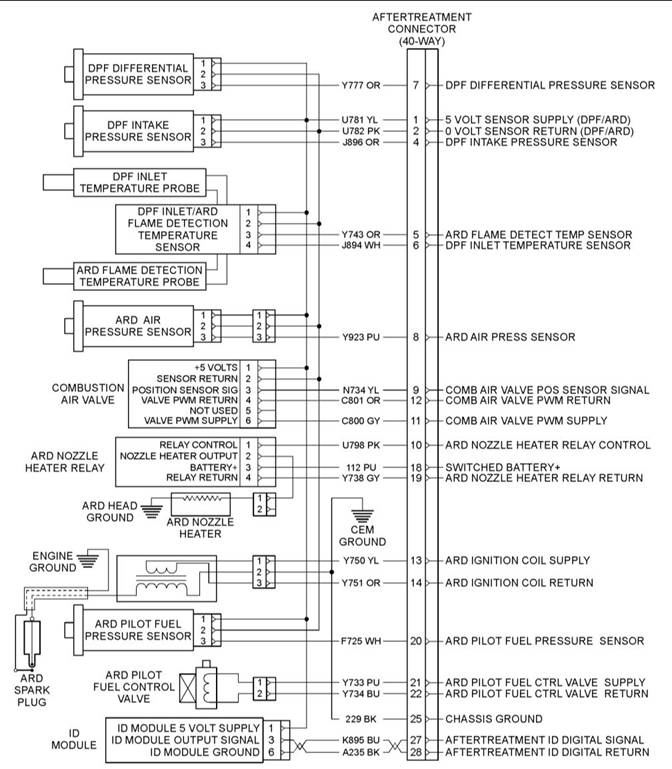
Illustration 16 |
|
g02362216 |
|
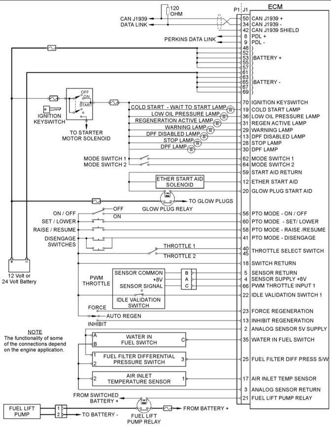
Schematic diagram of the Clean Emissions Module (CEM) Sheet 2 of 2 |
|
This document is printed from SPI². Not for RESALE |
![]()
![]()
|
32 |
|
KENR9101 |
|
Electronic Troubleshooting |
|
Illustration 17 |
|
g03360008 |
|
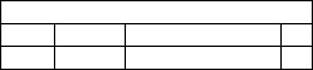
Schematic Diagram for a Typical Application |
|
This document is printed from SPI². Not for RESALE |
![]()
![]()
|
KENR9101 |
|
33 |
|
Electronic Troubleshooting |
|
i04021101 |
|
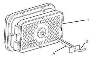
2. Position Tooling (A) around wire (2). |
|
ECM Harness Connector Terminals |
|
Note: Make sure that the tool stays perpendicular to the face of the connector (1). |
|
3. Push the tool into the hole for the terminal. Gently pull the wire in order to remove the terminal from the rear of the connector (1). |
|
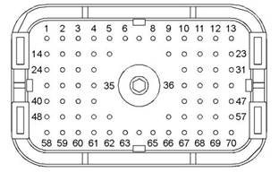
The Electronic Control Module (ECM) uses connectors that have 70 terminals to interface to the wiring harness. |
|
4. Remove the Tooling (A) from the wire. |
|
Note: If a terminal must be replaced, part number 2900A016 must be used for 16 and 18 AWG wire. Part number 28170024 must be used for 14 AWG wire. |
|
Terminal Insertion |
|
1. Push the terminal into the rear of the connector (1) until the terminal engages with the locking device. |
|
2. Gently pull on the wire (2) in order to make sure that the terminal is retained by the locking device. |
|
3. Connect the connector to the ECM and then tighten the retaining screw to a torque of 6 N·m (53 lb in). |
|
Illustration 18 |
|
g01877659 |
|
Layout of the Connector Pins (view from the rear) |
|
Removal and Installationof the Harness Connector Terminals |
|
Terminal Removal |
|
Table 6 |
|
Required Tools |
|
Tool A |
|
Part Number |
|
Part Description Removal Tool (Red) |
|
Qty |
|
2900A019 |
|
1 |
|
Illustration 19 |
|
g01877813 |
|
Removal Tool |
|
1. Remove the connector from the ECM. Refer to Disassembly and Assembly, “Electronic Control Module - Remove and Install”. |
|
This document is printed from SPI². Not for RESALE |
![]()
![]()
![]()
![]()
![]()
|
34 |
|
KENR9101 |
|
Programming Parameters |
|
Programming Parameters |
|
Note: “Test ECM Mode” can only be activated if the engine serial number has not already been programmed during normal operation of the ECM. If the engine serial number is programmed and the ECM is not in “Test ECM Mode” , the ECM can never be used as a test ECM. |
|
i03939853 |
|
Programming Parameters |
|
6. Use the “Copy Configuration” feature on the electronic service tool to program the test ECM. |
|
Note: If the “ECM Replacement” feature cannot be used, program the test ECM with the values from the “Customer Specified Parameters Worksheet” and the values from the System Configuration Parameters. |
|
The electronic service tool can be used to view certain parameters that can affect the operation of the engine. The electronic service tool can also be used to change certain parameters. The parameters are stored in the Electronic Control Module (ECM). Some of the parameters are protected from unauthorized changes by passwords. Parameters that can be changed have a tattletale number. The tattletale number is incremented whenever a parameter is changed. |
|
7. Program the engine serial number into the test ECM. |
|
Note: The “Test ECM Mode” must be activated before the engine serial number is programmed into the ECM. |
|
i03939990 |
|
8. Verify that the test ECM eliminates the fault. |
|
Test ECM Mode |
|
When the “Test ECM Mode” is activated, an internal timer sets a 24 hour clock. This clock will count down only while the ECM is powered and the keyswitch is in the ON position. After the ECM has counted down the 24 hour period, the ECM will exit the “Test ECM Mode” . The parameters and the engine serial number will be set. |
|
“Test ECM Mode” is a feature in the software that can be used to help troubleshoot an engine that may have a fault in the Electronic Control Module (ECM). This feature allows a standard ECM to be used as a test ECM. This feature eliminates the need to stock a test ECM. |
|
If the test ECM eliminates the fault, the engine can be released while the “Test ECM Mode” is still active. |
|
1. Search for the latest flash file for the engine. |
|
Once an ECM has been activated in the “Test ECM Mode” , the ECM will stay in the “Test ECM Mode” until the timer times out. If the ECM is used as a test ECM for more than one engine, the “Test ECM Mode” must be reactivated. Anytime prior to the “Test ECM Mode” timing out, the ECM can be reset to 24 hours. |
|
Note: If a newer software version is available for the engine, install the newest software on the suspect ECM. If the new software does not eliminate the fault, continue with this procedure. |
|
2. Use the “Copy Configuration” feature on the electronic service tool to copy the parameters from the suspect ECM. |
|
i04021107 |
|
Factory Passwords |
|
Note: If the “ECM Replacement” feature cannot be used, record the programmed values into the “Customer Specified Parameters Worksheet” . Also record the system configuration parameters. |
|
NOTICE |
|
Operating the engine with a flash file not designed for that engine will damage the engine. Be sure the flash file is correct for your engine. |
|
3. Disconnect the suspect ECM. Temporarily connect the test ECM to the engine. Do not mount the test ECM on the engine. |
|
Note: Factory passwords are provided only to Perkins authorized distributors. |
|
4. Flash program the test ECM with the newest software that is available. |
|
Factory passwords are required to perform each of the following functions: |
|
5. Start the “Test ECM Mode” on the electronic service tool. Access the feature through the “Service” menu. The electronic service tool will display the status of the test ECM and the hours that are remaining for the “Test ECM Mode” . |
|
This document is printed from SPI². Not for RESALE |
![]()
![]()
![]()
|
KENR9101 |
|
35 |
|
Programming Parameters |
|
• Program a new Electronic Control Module |
|
Note: You must have the engine serial number in |
|
(ECM). |
|
order to search for the part number of the flash file. |
|
When an ECM is replaced, the system configuration parameters must be programmed into the new ECM. A new ECM will allow these parameters to be programmed once without factory passwords. After the initial programming, some parameters are protected by factory passwords. |
|
2. Connect the electronic service tool to the diagnostic connector. |
|
3. Turn the keyswitch to the ON position. Do not start the engine. |
|
4. Select “WinFlash” from the “Utilities” menu on |
|
the electronic service tool. |
|
• Rerate the engine. |
|
Note: If “WinFlash” will not communicate with the ECM, refer to Troubleshooting, “Electronic Service Tool Does Not Communicate”. |
|
Rerating the engine may require changing the interlock code, which is protected by factory passwords. |
|
5. Flash program the flash file into the ECM. |
|
• Unlock parameters. |
|
a. b. |
|
Select the engine ECM under the “Detected ECMs” . |
|
Factory passwords are required in order to unlock certain system configuration parameters. Refer to Troubleshooting, “System Configuration Parameters”. |
|
Press the “Browse” button in order to select the part number of the flash file that will be programmed into the ECM. |
|
• Clear engine events and certain diagnostic |
|
trouble codes. |
|
c. d. |
|
When the correct flash file is selected, press the “Open” button. |
|
Most engine events require factory passwords in order to clear the code from ECM memory. Clear these codes only when you are certain that the fault has been corrected. For example, the 190- 15Engine Overspeed requires the use of factory passwords in order to clear the code from ECM memory. |
|
Verify that the “File Values” match the application. If the “File Values” do not match the application, search for the correct flash file. |
|
e. f. |
|
When the correct flash file is selected, press the “Begin Flash” button. |
|
Since factory passwords contain alphabetic |
|
The electronic service tool will indicate when flash programming has been successfully completed. |
|
characters, the electronic service tool must be used to perform these functions. In order to obtain factory passwords, proceed as if you already have the password. If factory passwords are needed, the electronic service tool will request the factory passwords. The electronic service tool will display the information that is required to obtain the passwords. |
|
6. Use the electronic service tool to check for diagnostic code 631-2. If this diagnostic code is active and the flash file is not being installed in order to change the engine rating, repeat this procedure from 1. If this diagnostic code is active and the flash file is being installed in order to change the engine rating, factory passwords must be obtained before the flash file will be accepted. |
|
i04021112 |
|
Flash Programming |
|
7. Access the “Configuration” screen under the “Service” menu in order to determine the |
|
Flash Programming – A method of loading a flash file into the Electronic Control Module (ECM) |
|
parameters that require programming. Look under the “Tattletale” column. All of the parameters should have a tattletale of 1 or more. If a parameter has a tattletale of 0, program that parameter. |
|
The electronic service tool is used to flash program a flash file into the ECM. The flash programming transfers the flash file from the PC to the ECM. |
|
Flash Programming a Flash File |
|
8. Start the engine and check for proper operation. |
|
Check that there are no active diagnostic codes. |
|
1. Obtain the part number for the new flash file. |
|
Note: If you do not have the part number for the flash file, use “PTMI” on the Perkins secured web site. |
|
This document is printed from SPI². Not for RESALE |