 English
 Espaol
 Franais
 阿拉伯
阿拉伯 中文
中文 Deutsch
 Italiano
 Português
 日本
日本 韩国
韩国 български
 hrvatski
 esky
esky Dansk
Dansk Nederlands
 suomi
suomi Ελληνικ
 印度
印度 norsk
norsk Polski
 Roman
Roman русский
 Svenska
Perkins1206-E70TTA柴油发动机涡轮增压器U000850Y供应商,Perkins1206-E70TTA柴油发动机涡轮增压器U000850Y技术价格规格咨询服务,Perkins1206-E70TTA柴油发动机涡轮增压器U000850Y零配件供应,Perkins1206-E70TTA柴油发动机涡轮增压器U000850Y售后服务中心,Perkins1206-E70TTA柴油发动机涡轮增压器U000850Y,Perkins1206-E70TTA柴油发动机涡轮增压器U000850Y详细的技术参数,

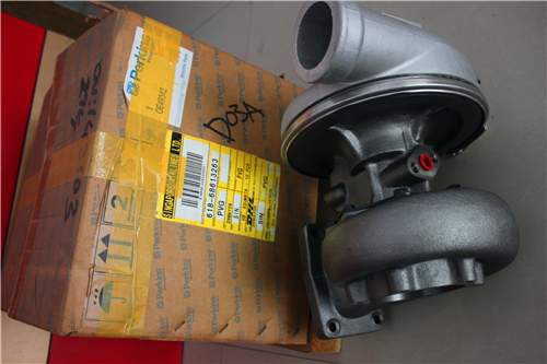
Perkins1206-E70TTA柴油发动机涡轮增压器U000850Y
详细描述
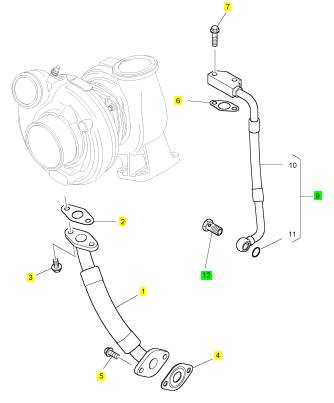
项目 零配件号码 新件号 描述
1 T407711 1 T415671 管
2 CH11561 1 CH11561 密封垫片
3 2314 H002 2 2314 H002 螺旋
4 3683 A022 1 3683 A022 密封垫片
5 2314 H003 2 2314 H003 螺旋
6 CH12205 1 CH12205 密封垫片
7 2314 H005 2 2314 H005 螺旋
9 T417970 1 T417970 管 - 涡轮增压器的油补给
9 T407851 1 检查历史 管
12 T418053 1 T418053 班卓琴螺拴
12 T407851 1 检查历史 管
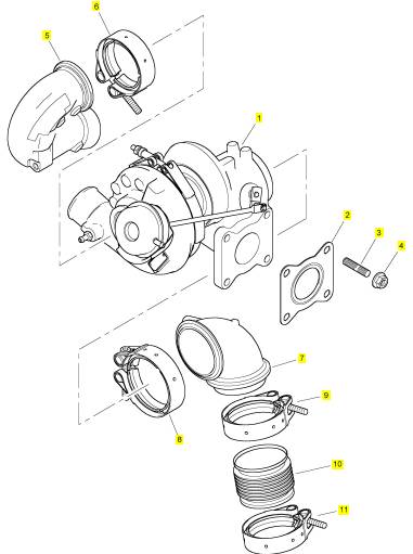
项目 零配件号码 新件号 描述
1 T419127 1 T419127 涡轮增压器 U000850Y
1 T412146 1 T419127 涡轮增压器
1 T417718 1 T419127 涡轮增压器 U000849Y
2 T407006 1 T407006 密封垫片
3 2313 M378 4 2313 M378 图钉
4 2318 A634 4 2318 A634 螺帽
5 T405987 1 T405987 导气管
6 T407169 1 T407169 砂箱夹
7 T412183 1 T412183 导气管
8 T409262 1 T409262 砂箱夹
9 T409262 1 T409262 砂箱夹
10 T410456 1 T410456 导气管
11 T409262 1 T409262 砂箱夹
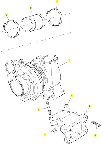
项目 零配件号码 新件号 描述
1 T412150 1 T412150 涡轮增压器
2 T405580 1 T405580 托架
3 2313 M383 4 2313 M383 图钉
4 2318 A634 4 2318 A634 螺帽
5 2313 T080 4 2313 T080 图钉
6 2318 A634 4 2318 A634 螺帽
7 T407961 1 T407961 水管
8 2481 D075 1 2481 D075 水管夹
9 2481 D075 1 2481 D075 水管夹
项目 零配件号码 新件号 描述
1 T418475 1 T418475 机油冷油器
2 3278 A006 1 3278 A006 栓塞
3 2415 H003 1 2415 H003 密封O型圈
4 2314 J018 2 2314 J018 螺旋
5 2314 J019 2 2314 J019 螺旋
6 T407196 1 T407196 管 -排气
9 2314 H004 2 2314 H004 螺旋
10 T407203 1 T407203 托架
11 2314 H005 2 2314 H005 螺旋
12 2314 J002 2 2314 J002 螺旋
13 T407726 1 T407726 管 -冷却器
16 2314 H004 4 2314 H004 螺旋
17 T415681 1 T415681 管 -冷却器
20 2314 H004 4 2314 H004 螺旋
21 T410790 1 T410790 管 -排气
24 T411589 1 T411589 螺拴
25 T411589 1 T411589 螺拴
26 T414193 1 T414193 接线夹
26 T412950 1 T414193 接线夹
26 T414193 1 T414193 接线夹

|
is document is printed from SPI². Not for RESALE |
![]()

![]()
![]()
|
KENR9101 |
|
15 |
|
Electronic Troubleshooting |
|
2. Connect cable (2) between the “COMPUTER” end of communication adapter (3) and the RS232 serial port of PC (1). |
|
On – The lamp will be on when the shutdown level in the engine protection strategy has been reached. The “Warning” lamp will also be on. |
|
Note: The Adapter Cable Assembly(4) is required to connect to the USB port on computers that are not equipped with an RS232 serial port. |
|
Warning Lamp |
|
3. Connect cable (4) between the “DATA LINK” end of communication adapter (3) and the service tool connector. |
|
Lamp check – When the keyswitch is turned to ON, the lamp will come on for 2 seconds. The lamp will then go off unless there is an active warning. |
|
Flashing – The lamp will be flashing when a “warning” or a “warning and derate” is active. This situation includes low oil pressure. |
|
4. Place the keyswitch in the ON position. If the Electronic Service Tool and the communication adapter do not communicate with the Electronic Control Module (ECM), refer to the diagnostic procedure Troubleshooting, “Electronic Service Tool DoesNot Communicate”. |
|
On – The lamp will be on when the shutdown level has been reached. The “Shutdown” lamp will also be on. |
|
i04805647 |
|
DPF Lamp |
|
Indicator Lamps |
|
Lamp check – When the keyswitch is turned to ON, the lamp will come on for 2 seconds. The lamp will then go off unless there is an active warning. |
|
On – The lamp will be on when a “warning” is active. The warning will occur when the level of soot in the DPF has reached 80 percent. The lamp will be on when the derate level has been reached. This situation will occur when the level of soot in the DPF has reached 100 percent. The “Warning” lamp will also be flashing. The lamp will be on when the shutdown level has been reached. This situation will occur when the level of soot in the DPF has reached 116 percent. The “Warning” lamp will also be flashing and the “Shutdown” lamp will be on. |
|
Indicator Lamps |
|
Seven lamps are available as options. The following five lamps will normally be installed in the application: |
|
• • • • • |
|
“Shutdown” lamp “Warning” lamp |
|
“DPF” lamp |
|
“DPF Disabled” lamp “Regeneration Active” lamp |
|
DPF Disabled Lamp |
|
Lamp check – When the keyswitch is turned to ON, the lamp will come on for 2 seconds. The lamp will then go off unless there is an active warning. |
|
The following two optional lamps for other items may also be installed: |
|
On – The lamp will be on when regeneration has been disabled by the operator or by the engine ECM. |
|
• • |
|
“Wait to start” lamp |
|
“Low oil pressure” lamp |
|
The “Shutdown” lamp and the “Warning” lamp can also be used to indicate a diagnostic trouble code by use of the “Flash Code” feature. The “Flash Code” feature can be used to indicate all active diagnostic codes and logged diagnostic codes. |
|
Regeneration Active Lamp |
|
Lamp check – When the keyswitch is turned to ON, the lamp will come on for 2 seconds. The lamp will then go off unless there is an active warning. |
|
Functions of the Lamps |
|
On – The lamp will be on during active regeneration when the machine is not operating under load and the outlet temperature of the DPF is more than 450° C (842° F). |
|
Shutdown Lamp |
|
Lamp check – When the keyswitch is turned to ON, the lamp will come on for 2 seconds. The lamp will then go off unless there is an active warning. |
|
Wait to Start Lamp |
|
Flashing – The lamp will be flashing when the engine is derated because of an active diagnostic code. An example of an active diagnostic code is “System Voltage High” . |
|
Lamp check – When the keyswitch is turned to ON, the lamp will come on for 2 seconds. The lamp will then go off unless “Wait to Start” is active. |
|
This document is printed from SPI². Not for RESALE |
|
On – The lamp is on during a “Wait to Start” period. |
![]()
|
16 |
|
KENR9101 |
|
Electronic Troubleshooting |
|
Low Oil Pressure |
|
Lamp check – When the keyswitch is turned to ON, the lamp will come on for 2 seconds. The lamp will then go off unless there is an active warning. |
|
On – The lamp will come on when a low oil pressure event is detected. The “Warning” lamp and the “Shutdown” lamp may also come on. |
|
Color of Lamps |
|
Typically, the “Shutdown” lamp is colored red and the “Warning” lamp is colored amber. The color of the other lamps can vary. |
|
This document is printed from SPI². Not for RESALE |
![]()
|
KENR9101 |
|
17 |
|
Electronic Troubleshooting |
|
Operation of the Indicator Lamps |
|
Table 4 |
|
Warning Lamp (Alert |
|
Shutdown Lamp (Action Lamp) |
|
Regen Active Lamp |
|
DPF Lamp |
|
DPF Dis- Lamp State abled Lamp |
|
Description of the Indication |
|
Engine State |
|
Lamp) |
|
On |
|
On |
|
On |
|
On |
|
On |
|
Lamp Check When the keyswitch is moved The keyswitch is in the ON po- to the ON position, the lamps sition but the engine has not come on for 2 seconds and the yet been cranked. lamps will then go off. |
|
Off On |
|
Off Off |
|
Off Off |
|
Off Off |
|
Off Off |
|
No Faults |
|
With the engine in operation, The engine is operating with there are no active warnings, no detected faults. diagnostic codes, or event |
|
codes. |
|
Active |
|
If the warning lamp comes on The engine is operating nor- |
|
Diagnostic |
|
during engine operation, the lamp indicates that an active |
|
mally but there is one or more faults with the electronic man- |
|
diagnostic code (an electrical agement system for the |
|
fault) is present. |
|
engine. |
|
On |
|
Flashing |
|
Off |
|
Off |
|
Off |
|
Derate |
|
If the warning lamp comes on The engine is operating but |
|
(An engine de- and the shutdown lamp flashes there is one or more active di- |
|
rate is caused during engine operation, an by certain ac- active diagnostic code (an tive codes.) electrical fault) is present. The diagnostic is sufficiently seri- |
|
agnostic codes that have initi- ated an engine derate. |
|
ous in order to cause an en- gine derate. |
|
Flashing |
|
Off |
|
Off |
|
Off |
|
Off |
|
Warning |
|
When the warning lamp |
|
The engine is operating nor- |
|
(Warning only) flashes during operation of the mally. However, there is one or engine, one or more of the more of the monitored engine warning values for the engine parameters that are outside of |
|
protection strategy has been exceeded. However, the value has not been exceeded to a level that will cause the engine to derate or a shutdown. |
|
the range that is acceptable. |
|
Flashing |
|
Flashing |
|
Off |
|
Off |
|
Off |
|
Derate (Warning and lamps flash if a value for the |
|
The warning and shutdown |
|
The engine is operating. How- ever, one or more of the moni- |
|
Derate) |
|
engine protection strategy has tored engine parameters is exceeded the level for an en- outside of the acceptable |
|
gine derate. |
|
range. The acceptable range has been exceeded to a level which requires a warning and an engine derate. |
|
(continued) |
|
This document is printed from SPI². Not for RESALE |

![]()
|
18 |
|
KENR9101 |
|
Electronic Troubleshooting |
|
(Table 4, contd) |
|
Warning Lamp (Alert |
|
Shutdown Lamp (Action Lamp) |
|
Regen Active Lamp |
|
DPF Lamp |
|
DPF Dis- Lamp State abled Lamp |
|
Description of the Indication |
|
Engine State |
|
Lamp) |
|
On |
|
On |
|
Off |
|
Off |
|
Off |
|
Engine Shutdown |
|
If both the warning lamp and the shutdown lamp come on during engine operation, one of the following conditions exists: |
|
The engine is either shutdown or an engine shutdown is immi- nent. One or more monitored engine parameters have ex- ceeded the limit for an engine shutdown. This pattern of lamps can be caused by the detection of a serious active di- agnostic code. |
|
1. One or more of the shut- down values for the engine protection strategy has been exceeded. |
|
2. A serious active diagnostic code has been detected. |
|
After a short time, the engine will shut down. |
|
Off |
|
Off |
|
On |
|
Off |
|
Off |
|
High exhaust The engine is operating at a |
|
If the engine is operating at a |
|
temperature |
|
low idle speed and the exhaust low idle speed, the exhaust system temperature is above temperature is high during an 450° C (842° F). The lamp will active regeneration.The ex- |
|
remain on until the exhaust temperature falls below 450 deg C, or the engine is oper- ated above the low idle speed. |
|
haust temperatureis also high during the cooling period im- mediately after an active regeneration. |
|
Off |
|
Off |
|
Off |
|
On |
|
Off |
|
High DPF soot The soot loading in the DPF is The soot loading in the DPF |
|
loading |
|
high. |
|
has reached 80%. The lamp warns the operator that an ac- tive regeneration is required. |
|
Off |
|
Off Off |
|
Off Off |
|
Off On |
|
On Off |
|
DPF is disabled. |
|
Active regeneration has been Active regenerationhas been disabled by the operator or the disabled. ECM. |
|
Flashing |
|
Very high DPF The soot loading in the DPF is The soot loading in the DPF |
|
soot loading |
|
high. |
|
has reached 100%. The en- gine will be derated. The lamp warns the operator that an ac- tive regeneration is required. |
|
Flashing |
|
On |
|
Off |
|
On |
|
Off |
|
Very high DPF The soot loading in the DPF is The soot loading in the DPF |
|
soot loading |
|
high. |
|
has reached 116%. The en- gine will be shut down after 5 minutes. The engine can be re- started and a regeneration should be performed. If a re- generation is not performed within 5 minutes, the engine will shut down again. The en- gine can be restarted. The electronic service tool must be used to perform a |
|
regeneration. |
|
Flash Codes |
|
The “Flash Code” feature is used to flash the code of all active diagnostic codes and logged diagnostic codes. |
|
This document is printed from SPI². Not for RESALE |

![]()
|
KENR9101 |
|
19 |
|
Electronic Troubleshooting |
|
The sequence for the flash code is started by cycling the keyswitch twice within a period of 3 seconds. After a delay of 2 seconds, the “Shutdown” lamp will flash once for half a second. This sequence indicates the start of the active fault codes. After a further delay of 2 seconds, the “Warning” lamp will flash repeatedly in order to indicate the active diagnostic codes. Each flash will be on for half a second and off for 300 ms. The “Warning” lamp will remain off for 2 seconds between each digit of a code. If there is more than one active diagnostic code, the “Shutdown” lamp will go off for 2 seconds. The lamp will then come on for half a second. The “Warning” lamp will go off for 2 seconds before starting the next code. If there are no active diagnostic codes, the “Warning” lamp will flash the code “551” . Refer to Troubleshooting Guide, “No Diagnostic Code Detected”. |
|
As an example, an active diagnostic code of “21” is indicated by the “Warning” lamp operating in the following sequence: |
|
• On for 500 ms • Off for 300 ms • On for 500 ms • Off for 2000 ms • On for 500 ms • Off |
|
Illustration 7 |
|
g01779334 |
|
Timing of the flash codes |
|
After all of the active diagnostic codes have been displayed, the “Shutdown” lamp will go off for 2 seconds. The “Shutdown” lamp will flash twice in order to indicate the start of the sequence that will display the logged diagnostic codes. The process for flashing logged diagnostic codes is identical to the process for flashing active diagnostic codes. |
|
Note: If there are no logged codes, the “551” code should be flashed again. |
|
This document is printed from SPI². Not for RESALE |

![]()
![]()
|
20 |
|
KENR9101 |
|
Electronic Troubleshooting |
|
After all of the codes have been displayed, the “Shutdown” lamp will flash three times in order to indicate that there are no further codes. Cycling the keyswitch twice within a period of 3 seconds will start the process again. All codes will be displayed in ascending numerical order. |
|
Use the electronic service tool to read the parameters in the suspect ECM. Record the parameters in the suspect ECM. Install the flash file into the new ECM. After the ECM is installed on the engine, the |
|
parameters must be programmed into the new ECM. |
|
Note: When a new ECM is not available, an ECM can be used from an engine that is not in service. The ECM must have the same serial number suffix. Ensure that the replacement ECM and the part number for the flash file match the suspect ECM. Be sure to record the parameters from the replacement ECM. Use the “Copy Configuration ECM |
|
Refer to the Troubleshooting Guide, “Diagnostic Code Cross Reference” for the diagnostic code that relates to the flash code. |
|
Note: Flash codes are always sent in ascending numerical order. |
|
Replacement” function in the electronic service tool. |
|
i04810790 |
|
NOTICE If the flash file and engine application are not matched, engine damage may result. |
|
Replacing the ECM |
|
Perform the following procedure in order to replace the ECM. |
|
NOTICE |
|
Care must be taken to ensure that fluids are con- tained during performance of inspection, mainte- nance, testing, adjusting and repair of the product. Be prepared to collect the fluid with suitable containers before opening any compartment or disassembling any component containing fluids. |
|
1. Connect the electronic service tool to the diagnostic connector. |
|
2. Use the “Copy Configuration ECM Replacement” function from the electronic service tool. If the “Copy Configuration” is successful, proceed to Step 4. If the “Copy Configuration” failed, proceed to Step 3. |
|
Dispose of all fluids according to local regulations and mandates. |
|
NOTICE |
|
Note: Record any Logged Faults and Events for your |
|
Keep all parts clean from contaminants. |
|
records. |
|
Contaminants may cause rapid wear and shortened component life. |
|
3. Record the following parameters: |
|
• Record all of the parameters on the |
|
“Configuration” screen. |
|
The engine is equipped with an Electronic Control Module (ECM). The ECM contains no moving parts. Follow the troubleshooting procedures in this manual in order to be sure that replacing the ECM will correct the fault. Verify that the suspect ECM is the cause of the fault. |
|
• Record all of the parameters on the “Throttle Configuration” screen. |
|
• Record all of the parameters on the “Mode Configuration” screen. |
|
Note: Ensure that the ECM is receiving power and that the ECM is properly grounded before replacement of the ECM is attempted. Refer to the schematic diagram. |
|
• Record the serial numbers of the electronic unit injectors. The injector serial numbers are shown on the “Injector Trim Calibration” screen. |
|
A test ECM can be used in order to determine if the ECM on the engine is faulty. Install a test ECM in place of the suspect ECM. Install the flash file with the correct part number into the test ECM. Program the parameters for the test ECM. The parameters must match the parameters in the suspect ECM. Refer to the following test steps for details. If the test ECM resolves the fault, reconnect the suspect ECM. Verify that the fault returns. If the fault returns, replace the ECM. |
|
Note: If the parameters cannot be read, the parameters must be obtained elsewhere. Some parameters are stamped on the engine information plate, but most parameters must be obtained from the TMI data on the Perkins secured web site. |
|
4. Remove power from the ECM. |
|
5. Remove the ECM. Refer to Disassembly and Assembly, “Electronic Control Module - Remove and Install”. |
|
Note: If an ECM is used as a test ECM, select “Test ECM Mode” on the electronic service tool before the engine serial number is entered. |
|
This document is printed from SPI². Not for RESALE |
![]()
![]()
![]()
![]()
![]()
![]()
![]()
|
KENR9101 |
|
21 |
|
Electronic Troubleshooting |
|
6. Install the replacement ECM. Refer to Disassembly and Assembly, “Electronic Control Module - Remove and Install”. |
|
i04628911 |
|
Self-Diagnostics |
|
7. If the replacement ECM is used as a test ECM, select “Test ECM Mode” on the electronic service tool. |
|
The Electronic Control Module (ECM) can detect faults in the electronic system and with engine operation. A self-diagnostic check is also performed whenever power is applied to the ECM. |
|
8. Download the flash file. |
|
a. |
|
Connect the electronic service tool to the diagnostic connector. |
|
When a fault is detected, a diagnostic trouble code is generated. This code conforms to the SAE J1939 standard. An alarm may also be generated. |
|
b. c. |
|
Select “WinFlash” from the “Utilities” menu of the electronic service tool. |
|
Diagnostic Trouble Code – When a fault in the electronic system is detected, the ECM generates a diagnostic trouble code. The diagnostic trouble code indicates the specific fault in the circuitry. |
|
Select the downloaded flash file. |
|
9. If necessary, use the electronic service tool to clear the rating interlock . To clear the rating interlock , enter the factory password when the electronic service tool is first connected. Activating the Test ECM mode will also clear the rating interlock . |
|
Diagnostic codes can have two different states: |
|
• Active |
|
• Logged |
|
10. Use the electronic service tool to program the parameters. Perform the following procedure. |
|
Active Code – An active diagnostic code indicates that an active fault has been detected by the control system. Active codes require immediate attention. Always service active codes prior to servicing logged codes. |
|
a. |
|
If the “Copy Configuration” procedure was successful, use the “Copy Configuration, ECM Replacement” function to load the |
|
Logged Code – Many generated codes are stored in the permanent memory of the ECM. The codes are logged for 100 operating hours unless a code is cleared by use of the electronic service tool. |
|
configuration file into the ECM. |
|
Note: During the following procedure, factory passwords may be required. |
|
b. |
|
If the “Copy Configuration” procedure failed, configure the parameters individually. The parameters should match the parameters from step 3. |
|
Logged codes may not indicate that a repair is needed. The fault may have been temporary. The fault may have been resolved since the logging of the code. If the system is powered, an active diagnostic trouble code may be generated whenever a |
|
Perform the “Fuel System Verification Test” . |
|
component is disconnected. When the component is reconnected, the code is no longer active. Logged codes may be useful to help troubleshoot intermittent faults. Logged codes can also be used to review the performance of the engine and the electronic system. |
|
11. Determine the most recent ash service of the Diesel Particulate Filter (DPF): |
|
a. |
|
If the DPF had an ash service within the last 500 hours, no action is required. |
|
i04810795 |
|
b. |
|
If the DPF was not ash serviced within 500 hours, perform an ash service on the DPF. Refer to Special Instruction REHS5045, “Diesel Particulate Filter (DPF) Maintenance on Tier 4 Products Equipped with a Diesel Particulate Filter (DPF)”. Refer to Systems Operation and Testing and Adjusting, “Diesel Particulate Filter - Clean” for the correct procedure. |
|
Sensors and Electrical Connectors |
|
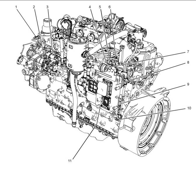
The Electronic Control Module (ECM) and most of the engine sensors are located on the left side of the engine. Refer to Illustration 8 . For the remaining sensors that are attached to the engine, refer to Illustration 10 . For the sensors and components on the Clean Emissions Module (CEM), refer to Illustration 12 . |
|
Note: After an ash service regeneration, there will be a delay in soot accumulation shown on the gauge. |
|
Note: In the following illustrations, some components |
|
have been removed in order to improve visibility. |
|
12. Check for logged diagnostic codes. Factory |
|
passwords are required to clear logged events. |
|
This document is prin, ted from SPI². Not for RESALE |
![]()
|
22 |
|
KENR9101 |
|
Electronic Troubleshooting |
|
Illustration 8 |
|
g02311267 |
|
Sensor locations on the left side of the engine |
|
(1) Coolant temperature sensor |
|
(5) Intake manifold pressure sensor |
|
(9) Barometric pressure sensor |
|
(2) Fuel temperature sensor (3) Solenoid for the high-pressure fuel pump (4) Intake manifold air temperature sensor |
|
(6) Fuel rail pressure sensor (7) 31-pin connector for the CEM (8) Electronic Control Module (ECM) |
|
(10) Primary speed/timing sensor (11) Oil pressure sensor |
|
This document is printed from SPI². Not for RESALE |
![]()
![]()