 English
 Espaol
 Franais
 阿拉伯
阿拉伯 中文
中文 Deutsch
 Italiano
 Português
 日本
日本 韩国
韩国 български
 hrvatski
 esky
esky Dansk
Dansk Nederlands
 suomi
suomi Ελληνικ
 印度
印度 norsk
norsk Polski
 Roman
Roman русский
 Svenska
Perkins1206-E70TTA柴油发动机汽缸盖供应商,Perkins1206-E70TTA柴油发动机汽缸盖技术价格规格咨询服务,Perkins1206-E70TTA柴油发动机汽缸盖零配件供应,Perkins1206-E70TTA柴油发动机汽缸盖售后服务中心,Perkins1206-E70TTA柴油发动机汽缸盖,Perkins1206-E70TTA柴油发动机汽缸盖详细的技术参数,

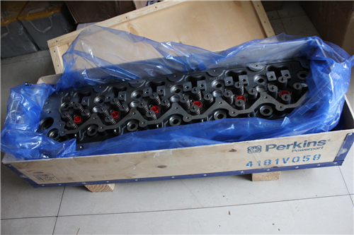
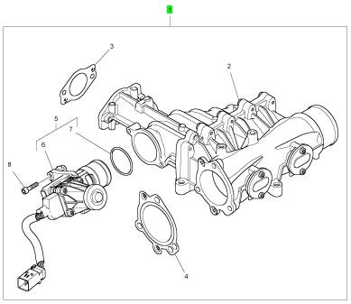
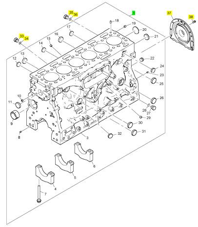
Perkins1206-E70TTA柴油发动机汽缸盖
详细描述
项目 零配件号码 新件号 描述
1 T410591 1 T410591 汽缸盖组合
项目 零配件号码 新件号 描述
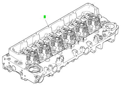
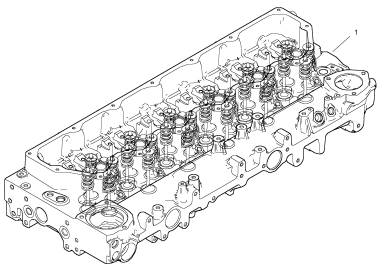
3 1 汽缸盖组合
14 2415 H003 1 2415 H003 密封O型圈
15 3278 A006 1 3278 A006 栓塞
16 2485 A307 1 2485 A307 栓塞
17 3278 A004 1 3278 A004 栓塞
18 2415 H654 1 2415 H654 密封O型圈
19 2415 H003 1 2415 H003 密封O型圈
20 3278 A006 1 3278 A006 栓塞
项目 零配件号码 新件号 描述
22 T406777 12 T406777 进气门
23 T412573 12 T412573 气门油封
24 T417519 12 T417519 阀弹簧
24 3174 A026 12 T417519 阀弹簧
25 T406809 12 T406809 承件
26 3142 W003 24 3142 W003 阀筒夹
27 T405211 12 T405211 排气阀
28 T412573 12 T412573 气门油封
29 T417713 12 T417713 阀弹簧
29 3174 A028 12 T417713 阀弹簧
30 T406809 12 T406809 承件
31 3142 W003 24 3142 W003 阀筒夹

项目 零配件号码 新件号 描述
2313 H244 1 2313 H244 图钉
2314 H013 2 2314 H013 螺旋
2318 A603 1 2318 A603 螺帽
T407823 1 T407823 间隔器
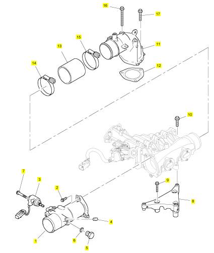
1 T419135 1 T419135 连接
1 T407309 1 T407309 连接
2 2314 H005 3 2314 H005 螺旋
3 T410311 1 T410311 电磁线圈
4 0650594 1 0650594 栓塞
5 3278 A006 1 3278 A006 栓塞
6 2415 H003 1 2415 H003 密封O型圈
7 2314 F006 2 2314 F006 螺旋
8 T408067 1 T408067 托架
9 2314 H008 3 2314 H008 螺旋
10 2314 H006 3 2314 H006 螺拴
11 T406266 1 T406266 管 -空气
12 T405741 1 T405741 密封垫片
13 T408073 1 T408073 水管 -空气
14 T410273 1 T410273 水管夹
15 T410273 1 T410273 水管夹
16 2314 H022 2 2314 H022 螺旋
17 2314 H008 1 2314 H008 螺旋
项目 零配件号码 新件号 描述
1 T410969 1 T421399 组件
项目 零配件号码 新件号 描述
2 1 组件
3 T405517 1 T405517 密封垫片
4 T405854 1 T405854 密封垫片
5 T410412 1 T410412 以计量器计量阀
8 2311 D040 2 2311 D040 螺旋

项目 零配件号码 Qty 。 新件号 描述
1 T408634 1 T408634 冷却器
2 T409185 2 T409185 螺帽

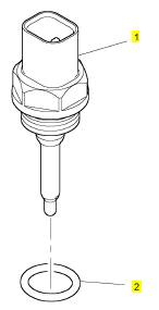
项目 零配件号码 新件号 描述
1 T407354 1 T407354 温度感应传感器
2 2415 H015 1 2415 H015 密封O型圈
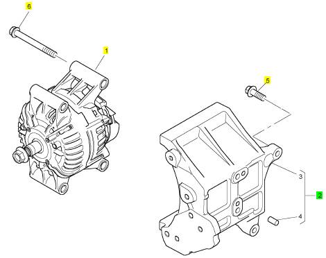
项目 零配件号码 新件号 描述
1 T412092 1 T412092 交流充电发电机
2 T412969 1 T412969 托架
5 2314 J005 4 2314 J005 螺旋
6 2314 J017 4 2314 J017 螺旋
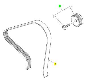
项目 零配件号码 新件号 描述
1 T411240 1 T411240 惰轮皮带轮
4 3508740 1 3508740 皮带
项目 零配件号码 新件号 描述
1 1 缸体组合
33 3278 A006 1 3278 A006 栓塞
34 2415 H519 1 2415 H519 密封O型圈
35 3278 A006 1 3278 A006 栓塞
36 2415 H003 1 2415 H003 密封O型圈
37 2418 F705 1 2418 F705 背面油密封壳
38 3211 C002 8 3211 C002 公制的螺拴
项目 零配件号码 新件号 描述
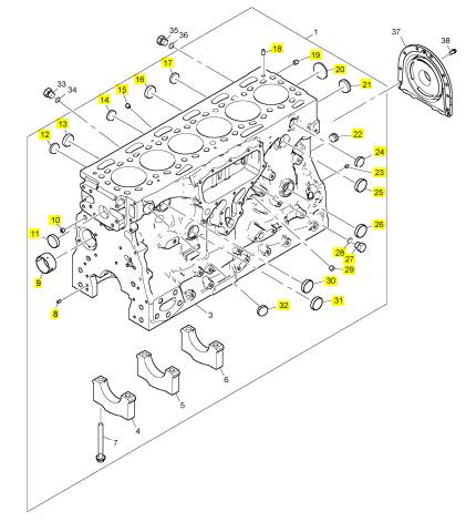
2 1 缸体组合
8 0350010 1 0350010 合钉
9 T410164 1 T410164 凸轮轴衬套
10 2485 A309 1 2485 A309 栓塞
11 2485 A526 1 2485 A526 栓塞
12 0650710 1 0650710 栓塞
13 3241 A011 1 3241 A011 栓塞
14 0650710 1 0650710 栓塞
15 2485 A309 1 2485 A309 栓塞
16 3241 A011 1 3241 A011 栓塞
17 0650710 1 0650710 栓塞
18 3244 A009 2 3244 A009 合钉
19 2485 A309 1 2485 A309 栓塞
20 2485 A526 1 2485 A526 栓塞
21 3241 A012 1 3241 A012 栓塞
22 3212 P008 1 3212 P008 栓塞
23 0350010 1 0350010 合钉
24 0650710 1 0650710 栓塞
25 2485 A526 1 2485 A526 栓塞
26 2485 A526 1 2485 A526 栓塞
27 3278 A006 1 3278 A006 栓塞
28 2415 H003 1 2415 H003 密封O型圈
29 2485 A309 1 2485 A309 栓塞
30 2485 A526 1 2485 A526 栓塞
31 2485 A526 1 2485 A526 栓塞
32 0650710 1 0650710 栓塞
项目 零配件号码 新件号 描述
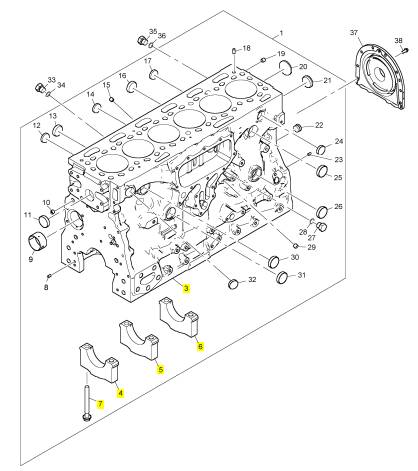
3 1 缸体
4 1 轴承盖
5 5 轴承盖
6 1 轴承盖
7 3218 A511 14 3218 A511 螺旋
项目 零配件号码 新件号 描述
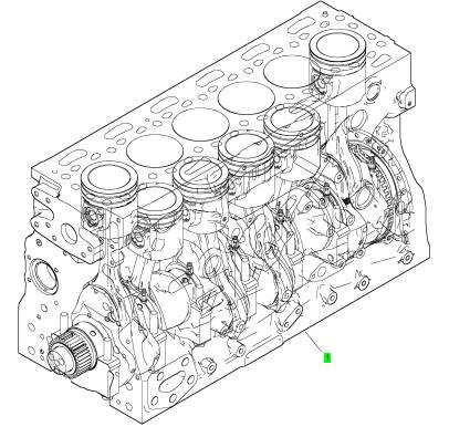
1 T415124 1 T415124 短引擎 -组合
|
Troubleshooting |
|
1206E-E70TTA Industrial Engine |
|
BL (Engine) |
|
This document is printed from SPI². Not for RESALE |
![]()
![]()
![]()
![]()

|
Important Safety Information |
|
Most accidents tha t involve produc t op eration, ma intena nc e and repair are caus ed by failure to ob serve basic safety rules or precautions . An accident can often be avoided by recog nizing pote ntially ha za rdous situations before an accident oc curs . A person mus t be alert to pote ntial ha za rds. This person should also ha ve the ne cessary training, skills and tools to perform the se func tions properly. |
|
Improper operation, lubrication, maintenance or repair of this product can be dangerous and could result in injury or death. |
|
Do not operate or perform any lubrication, maintenance or repair on this product, until you have read and understood the operation, lubrication, maintenance and repair information. |
|
Sa fety precautions and warning s are provided in this ma nua l and on the produc t. If the se ha za rd warning s are not he eded, bod ily injury or death could oc cur to you or to othe r persons . |
|
The ha za rds are identified by the “Safety Alert Symb ol” and followed by a “Signa l Word” suc h as “DANGER”, “WARNING” or “CAUTION”. The Sa fety Alert “WARNING” label is shown below. |
|
The me aning of this safety alert symb ol is as follows: |
|
Attention! Become Alert! Your Safety is Involved. |
|
The me ssage tha t appears und er the warning explains the ha za rd and can be either written or pictorially presente d. |
|
Op erations tha t ma y caus e produc t dama ge are identified by “NOTICE” labels on the produc t and in this pub lication. |
|
Perkins cannot anticipate every possible circumstance that might involve a potential hazard. The warnings in this publication and on the product are, therefore, not all inclusive. If a tool, procedure, work method or operating technique that is not specifically recommended by Perkins is used, you must satisfy yourself that it is safe for you and for others. You should also ensure that the product will not be damaged or be made unsafe by the operation, lubrication, maintenance or repair procedures that you choose. |
|
The informa tion, specifications , and illustrations in this pub lication are on the basis of informa tion tha t was available at the time tha t the pub lication was written. The specifications , torque s, pressure s, me asure me nts , adjustme nts , illustrations , and othe r items can cha ng e at any time. These cha ng es can affect the service tha t is given to the produc t. Ob tain the comp lete and mos t current informa tion before you start any job. Pe rkins dealers or Pe rkins distributors ha ve the mos t current informa tion available. |
|
When replacement parts are required for this product Perkins recommends using Perkins replacement parts. Failure to heed this warning can lead to prema- ture failures, product damage, personal injury or death. |
|
This document is printed from SPI². Not for RESALE |
![]()
![]()
|
KENR9101 |
|
3 |
|
Table of Contents |
|
Table of Contents |
|
Cylinder Is Noisy....................... ...................... 93 Diesel Particulate Filter Collects Excessive |
|
Soot ............................... ............................... 94 Diesel Particulate Filter Has High Ash Load.. . 97 Diesel Particulate Filter Has High Inlet Pressure ............................ ........................... 97 Diesel Particulate Filter Has Low Inlet Pressure ............................ ........................... 99 Diesel Particulate Filter Requires Initial Regeneration ....................... ....................... 100 Diesel Particulate Filter Temperature Is High 101 Diesel Particulate Filter Temperature Is Low 102 ECM Does Not Communicate with Other |
|
TroubleshootingSection |
|
Electronic Troubleshooting |
|
Welding Precaution ..................... ..................... 5 System Overview....................... ....................... 5 Glossary .............................. ............................. 9 Electronic Service Tools ................. ................ 13 Indicator Lamps....................... ....................... 15 Replacing the ECM..................... .................... 20 Self-Diagnostics....................... ....................... 21 Sensors and Electrical Connectors ........ ........ 21 Engine Wiring Information............... ............... 26 ECM Harness Connector Terminals........ ....... 33 |
|
Modules........................... ........................... 103 ECM Will Not Accept Factory Passwords... .. 104 Electronic Service Tool Does Not |
|
Communicate....................... ....................... 104 Engine Cranks but Does Not Start........ ........ 105 Engine Does Not Crank................ ................ 109 Engine Has Early Wear ................ ................ 109 Engine Has Mechanical Noise (Knock).... .....110 Engine Misfires, Runs Rough or Is Unstable. 111 Engine Overspeeds................... ....................115 Engine Shutdown Occurs Intermittently.... ....116 Engine Speed Does Not Change ......... .........117 Engine Stalls at Low RPM.............. ...............118 Engine Top Speed Is Not Obtained....... ....... 120 Engine Vibration Is Excessive........... ........... 124 Exhaust Has Excessive Black Smoke..... ..... 125 Exhaust Has Excessive White Smoke .... ..... 128 Fuel Consumption Is Excessive .......... ......... 130 Fuel Contains Water................... .................. 132 Fuel Rail Pressure Problem............. ............. 133 Fuel Temperature Is High ............... .............. 140 Inlet Air Is Restricted................... .................. 141 Inlet Air Temperature Is High ............ ............ 141 Intake Manifold Air Pressure Is High ...... ...... 142 Intake Manifold Air Pressure Is Low....... ...... 143 Intake Manifold Air Temperature Is High.... ... 145 NRS Exhaust Gas Temperature Is High.... ... 146 NRS Mass Flow Rate Problem........... .......... 149 Oil Consumption Is Excessive........... ........... 151 Oil Contains Coolant................... .................. 153 Oil Contains Fuel..................... ..................... 153 Oil Pressure Is Low.................... ................... 154 Power Is IntermittentlyLow or Power Cutout Is Intermittent......................... ......................... 157 Valve Lash Is Excessive................ ............... 161 |
|
Programming Parameters |
|
Programming Parameters ............... ............... 34 Test ECM Mode....................... ....................... 34 Factory Passwords..................... .................... 34 Flash Programming.................... .................... 35 Injector Code - Calibrate................. ................ 36 Mode Switch Setup..................... .................... 37 Throttle Setup......................... ........................ 38 Multiposition Switch Setup............... ............... 41 |
|
Customer Specified Parameters |
|
Customer Specified Parameters........... .......... 42 Customer Specified Parameters Table...... ..... 49 Customer Specified Parameters Worksheet . . 54 |
|
System ConfigurationParameters System Configuration Parameters......... ......... 58 |
|
Symptom Troubleshooting |
|
Acceleration Is Poor or Throttle Response Is Poor ............................... ............................... 59 Alternator Is Noisy ..................... ..................... 63 Alternator Problem..................... ..................... 64 ARD Combustion Supply Air Pressure Is Low 64 ARD Failed to Ignite.................... .................... 66 ARD Is Disabled ....................... ...................... 72 ARD Loss of Combustion................ ............... 73 ARD Pilot Fuel Pressure Is High........... .......... 76 ARD Pilot Fuel Pressure Is Low ........... .......... 81 ARD Temperature Is Low................ ................ 84 Battery Problem....................... ....................... 88 Coolant Contains Oil.................... ................... 88 Coolant Level Is Low ................... ................... 89 Coolant Temperature Is High............. ............. 90 |
|
Troubleshootingwith a Diagnostic Code Diagnostic Trouble Codes .............. .............. 162 |
|
This document is printed from SPI². Not for RESALE |
![]()
|
4 |
|
KENR9101 |
|
Table of Contents |
|
Diagnostic Code Cross Reference........ ....... 170 No Diagnostic Codes Detected .......... .......... 176 |
|
Troubleshootingwith an Event Code Event Codes......................... ........................ 177 |
|
Diagnostic Functional Tests |
|
5 Volt Sensor Supply Circuit - Test ................ 179 Analog Throttle Position Sensor Circuit - Test189 ARD Fuel Supply - Test ................ ................ 194 ARD Ignition - Test.................... .................... 201 ARD Nozzle - Test .................... .................... 216 ARD Nozzle Heater - Test............... .............. 219 CAN Data Link Circuit - Test............. ............ 236 Data Link Circuit - Test................. ................. 240 Diesel Particulate Filter Identification Signal - Test ............................... .............................. 246 Digital Throttle Position Sensor Circuit - Test 252 ECM Memory - Test................... ................... 261 Electrical Connectors - Inspect........... .......... 261 Engine Pressure Sensor Open or Short Circuit - Test ............................... .............................. 266 Engine Speed/Timing Sensor Circuit - Test. . 279 Engine Temperature Sensor Open or Short |
|
Circuit - Test........................ ........................ 286 Engine Temperature Sensor Open or Short |
|
Circuit - Test........................ ........................ 293 Ether Starting Aid - Test................ ................ 301 Fuel Pump Relay Circuit - Test ........... .......... 305 Glow Plug Starting Aid - Test............ ............ 313 Idle Validation Switch Circuit - Test........ ....... 319 Ignition Keyswitch Circuit and Battery Supply Circuit - Test........................ ........................ 325 Indicator Lamp Circuit - Test............. ............ 332 Injector Data Incorrect - Test............. ............ 335 Injector Solenoid Circuit - Test........... ........... 337 Mode Selection Circuit - Test............ ............ 343 Motorized Valve - Test ................. ................. 347 PTO Switch Circuit - Test............... ............... 355 Sensor Calibration Required - Test........ ....... 358 Solenoid Valve - Test.................. .................. 361 Soot Sensor - Test .................... .................... 370 Throttle Switch Circuit - Test............. ............ 374 Valve Position Sensor - Test............. ............ 378 Water In Fuel Sensor - Test ............. ............. 389 |
|
Index Section |
|
Index............................... .............................. 394 |
|
This document is printed from SPI². Not for RESALE |
![]()
|
KENR9101 |
|
5 |
|
Electronic Troubleshooting |
|
TroubleshootingSection |
|
Electronic Troubleshooting |
|
i04029202 |
|
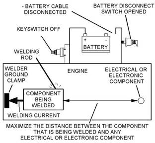
Welding Precaution |
|
Correct welding procedures are necessary in order to avoid damage to the following components: |
|
• Electronic Control Module (ECM) on the engine • Clean Emissions Module (CEM) • Sensors |
|
Illustration 1 |
|
g01143634 |
|
• Associated components |
|
Service welding guide (typical diagram) |
|
Components for the driven equipment should also be considered. When possible, remove the component that requires welding. When welding on an engine that is equipped with an ECM and removal of the component is not possible, the following procedure must be followed. This procedure minimizes the risk to the electronic components. |
|
5. When possible, connect the ground clamp for the welding equipment directly to the engine |
|
component that will be welded. Place the clamp as close as possible to the weld. Close positioning reduces the risk of welding current damage to the engine bearings, to the electrical components, and to other components. |
|
1. Stop the engine. Remove the electrical power from |
|
the ECM. |
|
6. Protect the wiring harnesses from welding debris |
|
2. Ensure that the fuel supply to the engine is turned |
|
and/or from welding spatter. |
|
off. |
|
7. Use standard welding procedures to weld the materials together. |
|
3. Disconnect the negative battery cable from the battery. If a battery disconnect switch is installed, open the switch. |
|
i03769809 |
|
4. Disconnect all electronic components from the wiring harnesses. Include the following components: |
|
System Overview |
|
• Electronic components for the driven equipment |
|
The engine has an electronic control system. The system controls the engine and the Aftertreatment Regeneration Device (ARD). The system monitors the Diesel Particulate Filter (DPF). |
|
• ECM |
|
• Sensors |
|
The control system consists of the following components: |
|
• Electronically controlled valves • Relays |
|
• Electronic Control Module (ECM) • Software (flash file) • Wiring |
|
• Aftertreatment ID module |
|
NOTICE |
|
• Sensors |
|
Do not use electrical components (ECM or ECM sen- sors) or electronic component grounding points for grounding the welder. |
|
• Actuators |
|
This document is printed from SPI². Not for RESALE |
![]()
![]()
![]()
![]()
![]()
|
6 |
|
KENR9101 |
|
Electronic Troubleshooting |
|
The following information provides a general description of the control system. Refer to Systems Operation, Testing, and Adjusting for detailed information about the control system. |
|
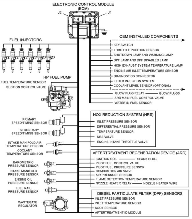
Electronic Control Circuit Diagram |
|
Illustration 2 |
|
g02228013 |
|
Electronic control circuit diagram |
|
This document is printed from SPI². Not for RESALE |
![]()
![]()
|
KENR9101 |
|
7 |
|
Electronic Troubleshooting |
|
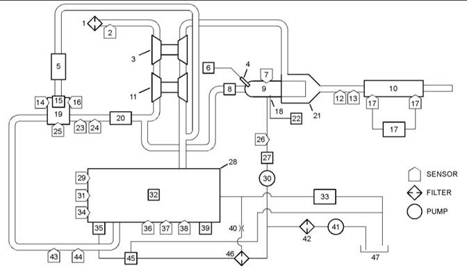
Block Diagram |
|
Illustration 3 is a block diagram of the control system. |
|
Illustration 3 |
|
g02356236 |
|
Block diagram |
|
(1) Air cleaner |
|
(17) Soot sensor |
|
(34) Secondary speed/timing sensor |
|
(2) Air inlet temperaturesensor (3) Low-pressure turbocharger (4) Spark plug |
|
(18) ARD heater wire (19) NRS mixer (20) Air-to-airaftercooler (21) ARD body |
|
(35) High-pressurefuel pump/transfer pump/ fuel temperaturesensor (36) Fuel rail pressure sensor (37) Oil pressure sensor |
|
(5) NRS cooler |
|
(6) Ignition coil |
|
(22) Heater relay |
|
(38) Barometric pressure sensor (39) ECM (40) Secondary fuel filter air purge restrictor (41) Fuel transfer pump |
|
(7) Flame detection temperature sensor (8) ARD combustion air valve (9) ARD combustion head (10) Diesel Oxidation Catalyst (DOC) and Diesel Particulate Filter (DPF) (11) High-pressure turbocharger (12) DPF inlet pressure sensor (13) DPF inlet temperaturesensor (14) NRS temperaturesensor (15) NRS valve |
|
(23) Intake throttle valve (24) Wastegate regulator (25) NRS differential pressure sensor (26) Pilot fuel pressure sensor (27) Pilot fuel control valve (28) Engine (29) Coolant temperature sensor (30) ARD fuel pump (31) Primary speed/timing sensor (32) Fuel injectors |
|
(42) Primary fuel filter |
|
(43) Intake manifold pressure sensor (44) Intake manifold air temperature sensor (45) Transfer pump inlet regulator (46) Secondary fuel filter |
|
(47) Fuel tank |
|
(16) NRS inlet pressure sensor |
|
(33) Return fuel cooler |
|
System Operation |
|
The governor uses the throttle position sensor to determine the desired engine speed. The governor compares the desired engine speed to the actual engine speed. The actual engine speed is determined through interpretation of the signals that are received by the ECM from the engine speed/timing sensors. If the desired engine speed is greater than the actual engine speed, the governor injects more fuel in order to increase engine speed. |
|
Engine Governor |
|
The ECM governs the engine. The ECM determines the timing, the injection pressure, and the amount of fuel that is delivered to each cylinder. These factors are based on the actual conditions and on the desired conditions at any given time during starting and operation. |
|
This document is printed from SPI². Not for RESALE |
![]()
![]()
|
8 |
|
KENR9101 |
|
Electronic Troubleshooting |
|
• Injection timing • Fuel delivery |
|
The flash file inside the ECM establishes certain limits on the amount of fuel that can be injected. The “FRC Fuel Limit” is a limit that is based on the intake manifold pressure. The “FRC Fuel Limit” is used to control the air/fuel ratio for control of emissions. When the ECM senses a higher intake manifold pressure, the ECM increases the “FRC Fuel Limit” . A higher intake manifold pressure indicates that there is more air in the cylinder. When the ECM increases the “FRC Fuel Limit” , the ECM allows more fuel into the cylinder. |
|
The “Rated Fuel Limit” is a limit that is based on the power rating of the engine and on the engine rpm. The “Rated Fuel Limit” is like the rack stops and the torque spring on a mechanically governed engine. The “Rated Fuel Limit” provides the power curves and the torque curves for a specific engine family and a specific engine rating. All of these limits are determined at the factory. These limits cannot be changed. |
|
Illustration 4 |
|
g01860934 |
|
Typical example |
|
Customer Parameters and Engine Speed Governing |
|
The desired engine speed is typically determined by one of the following conditions: |
|
• The position of the throttle |
|
A unique feature with electronic engines is customer specified parameters. These parameters allow the owner of the machine to fine-tune the ECM for engine operation. Fine-tuning the ECM allows the machine owner to accommodate the typical usage of the machine and the power train of the machine. |
|
• The desired engine speed in Power Take-Off (PTO) |
|
Timing Considerations |
|
Many of the customer parameters provide additional restrictions on the actions that will be performed by the ECM in response to input from the operator. The “PTO Top Engine Limit” is an engine rpm limit that is used by the ECM to limit the fuel during operation of the PTO. The ECM will not fuel the injectors above this rpm. |
|
Once the governor has determined the amount of fuel that is required, the governor must determine the timing of the fuel injection. Fuel injection timing is determined by the ECM after considering input from the following components: |
|
• Coolant temperature sensor |
|
Some parameters are intended to notify the operator of potential engine damage (engine monitoring parameters). Some parameters enhance fuel economy (machine speed, engine speed limit, and idle shutdown). Other parameters are used to enhance the engine installation into the machine. Other parameters are used to provide engine operating information to the owner of the machine. |
|
• Intake manifold air temperature sensor • Intake manifold pressure sensor • Barometric pressure sensor |
|
The ECM adjusts timing for optimum engine |
|
performance and for fuel economy. Actual timing and desired timing cannot be viewed with the electronic service tool. The ECM determines the location of top center of the number one cylinder from the signals that are provided by the engine speed/timing sensors. The ECM determines when injection should occur relative to top center. The ECM then provides the signal to the injector at the desired time. |
|
Other ECM Functions for Performance |
|
The ECM can also provide enhanced control of the engine for machine functions such as controlling the cooling fan. Refer to Troubleshooting, “Customer Specified Parameters” for additional information. |
|
Fuel Injection |
|
ECM Lifetime Totals |
|
The ECM sends a high voltage signal to the injector solenoids in order to energize the solenoids. By controlling the timing and the duration of the high voltage signal, the ECM can control the following aspects of injection: |
|
The ECM maintains total data of the engine for the following parameters: |
|
This document is printed from SPI². Not for RESALE |