English
 Espaol
 Franais
 阿拉伯
阿拉伯 中文
中文 Deutsch
 Italiano
 Português
 日本
日本 韩国
韩国 български
 hrvatski
 esky
esky Dansk
Dansk Nederlands
 suomi
suomi Ελληνικ
 印度
印度 norsk
norsk Polski
 Roman
Roman русский
 Svenska
Perkins1204柴油发动机配件供应商,Perkins1204柴油发动机配件技术价格规格咨询服务,Perkins1204柴油发动机配件零配件供应,Perkins1204柴油发动机配件售后服务中心,Perkins1204柴油发动机配件,Perkins1204柴油发动机配件详细的技术参数,

Perkins1204柴油发动机配件
详细描述
|
3. Use the electronic service tool to verify the throttle position status. |
|
Note: The turbocharger that is installed on the engine is a nonserviceable item. If any mechanical fault exists, then the turbocharger must be replaced. |
|
4. Run the engine until the speed is equal to the maximum no-load speed. |
|
1. Ensure that the mounting bolts for the turbocharger |
|
are tight. |
|
5. Use the electronic service tool to make sure that the throttle is set to reach the maximum no-load speed. |
|
2. Check that the oil feed for the turbocharger is not blocked or restricted. |
|
6. If the maximum no-load speed cannot be obtained refer to Troubleshooting, “Throttle Switch Circuit - Test” and Troubleshooting, “Mode Selection Circuit - Test”. |
|
3. Check that the oil drain for the turbocharger is not blocked or restricted. |
|
4. Check that the compressor housing for the turbocharger is free of dirt, debris, and damage. |
|
7. If the engine speed is erratic refer to Troubleshooting, “Analog Throttle Position Sensor Circuit - Test” or Troubleshooting, “Digital Throttle Position Sensor Circuit - Test”. |
|
5. Check that the turbine housing for the turbocharger is free of dirt, debris, damage, and oil deposits. |
|
6. Check that the turbine wheel rotates freely in the turbocharger. Make sure that the compressor wheel rotates with the turbine wheel. |
|
8. If the fault has not been eliminated, proceed to “Air Intake and Exhaust System”. |
|
Air Intake and Exhaust System |
|
7. Ensure that the wastegate on the turbocharger is operating correctly. Refer to Systems Operation, Testing and Adjusting, “Turbocharger - Inspect”. If the wastegate actuator is faulty, replace the turbocharger. Refer to Disassembly and Assembly, “Turbocharger - Remove” and Disassembly and Assembly, “Turbocharger - Install”. |
|
1. Check the air filter restriction indicator, if equipped. 2. Ensure that the air filter is clean and serviceable. |
|
3. Check the air intake and the exhaust system for |
|
the following defects: |
|
8. If necessary, replace the turbocharger. Refer to Disassembly and Assembly, “Turbocharger - Remove” and Disassembly and Assembly, “Turbocharger - Install”. |
|
• Blockages |
|
• Restrictions |
|
9. Check that the repairs have eliminated the faults. |
|
• Damage to the air intake and exhaust lines and hoses |
|
10. If the fault has not been eliminated, proceed to |
|
“Fuel Supply”. |
|
4. Make all necessary repairs to the engine. |
|
Turbochargers |
|
5. If the fault has not been eliminated, proceed to |
|
“Valve Lash”. |
|
This procedure is applicable only to engines that have two turbochargers. |
|
Valve Lash |
|
Note: The turbochargers that are installed on the engine are nonserviceable items. If any mechanical fault exists, then the faulty turbocharger must be replaced. |
|
1. Check the valve lash. Refer to Systems Operation, Testing and Adjusting, “Engine Valve Lash - Inspect”. |
|
2. If any repair does not eliminate the fault, proceed to “Turbochargers”. |
|
1. Ensure that the mounting bolts for the turbochargers are tight. |
|
Turbocharger or Turbochargers |
|
2. Check that the oil feeds for the turbochargers are |
|
not blocked or restricted. |
|
Turbocharger |
|
3. Check that the oil drains for the turbochargers are not blocked or restricted. |
|
This procedure is applicable only to engines that have a single turbocharger. |
|
4. Check that the compressor housings for the turbochargers are free of dirt, debris, and damage. |
|
This document is printed from SPI². Not for RESALE |
![]()
|
62 |
|
KENR9116-01 |
|
Troubleshooting Section |
|
5. Check that the turbine housings for the turbochargers are free of dirt, debris, damage, and oil deposits. |
|
11. Check for air in the fuel system. Refer to Systems Operation, Testing and Adjusting, “Air in Fuel - Test”. |
|
6. Check that the turbine wheels rotate freely in the turbochargers. Make sure that the compressor wheels rotate with the turbine wheels. |
|
12. Ensure that the fuel system has been primed. Refer to Systems Operation, Testing and Adjusting, “Fuel System - Prime”. |
|
7. Ensure that the wastegate on the high-pressure turbocharger is operating correctly. Refer to Systems Operation, Testing and Adjusting, “Turbocharger - Inspect”. If the wastegate actuator is faulty, replace the turbocharger. Refer to Disassembly and Assembly, “Turbocharger - Remove” and Disassembly and Assembly, “Turbocharger - Install”. |
|
13. Turn the keyswitch to the OFF position and then disconnect the electrical connector from the EFLP. |
|
14. With the keyswitch in the ON position, measure the voltage at the harness connector for the EFLP. The voltage must be between 10 VDC and 14 VDC for a 12 VDC system. The voltage must be between 20 VDC and 28 VDC for a 24 VDC system. If the voltage is below 10 VDC for a 12 VDC system, investigate the cause. If the voltage is below 20 VDC for a 24 VDC system, investigate the cause. Refer to Troubleshooting, “Fuel Pump Relay Circuit - Test”. |
|
8. If a fault is identified in either turbocharger, replace the affected turbocharger. Refer to Disassembly and Assembly, “Turbocharger - Remove” and Disassembly and Assembly, “Turbocharger - Install”. |
|
15. Turn the keyswitch to the OFF position and then reconnect the electrical connector to the EFLP. |
|
9. Check that the repairs have eliminated the faults. |
|
10. If the fault has not been eliminated, proceed to “Fuel Supply”. |
|
16. If a repair has been performed to rectify a low supply voltage to the EFLP, attempt to start the engine. If the engine does not start, continue with this procedure. |
|
Fuel Supply |
|
Note: Before performing the following fuel system tests, the engine must be stopped for a minimum of 30 minutes. |
|
1. Visually check the fuel tank for fuel. The fuel gauge may be faulty. |
|
2. Ensure that the fuel supply valve (if equipped) is in the full OPEN position. |
|
Note: When performing the following fuel system tests, the Electric Fuel Lift Pump (EFLP) will only operate for 2 minutes unless the engine is running. If necessary, cycle the keyswitch in order to reactivate the pump. |
|
3. If the temperature is below 0 °C (32 °F), check for solidified fuel (wax). |
|
4. Check the primary filter/water separator for water in the fuel. |
|
5. Check for fuel supply lines that are restricted. |
|
6. Check that the low-pressure fuel lines are tight and secured properly. |
|
7. Check that the Electric Fuel Lift Pump (EFLP) is operating. If the EFLP is suspect, refer to Troubleshooting, “Fuel Pump Relay Circuit - Test”. |
|
8. Replace the in-line fuel strainer that is installed upstream from the EFLP. |
|
9. Replace the primary fuel filter and the secondary fuel filter. Refer to the Operation and Maintenance Manual, “Fuel System Primary Filter (Water Separator) Element - Replace”. |
|
10. Check the diesel fuel for contamination. Refer to Systems Operation, Testing and Adjusting, “Fuel Quality - Test”. |
|
This document is printed from SPI². Not for RESALE |
![]()
|
KENR9116-01 |
|
63 Troubleshooting Section |
|
1. Disconnect the TPIR return line from the drain port on the TPIR. Install a suitable blanking cap on the open port in the TPIR return line |
|
2. Connect a temporary drain line to the drain port on the TPIR. |
|
3. Place the end of the temporary drain line into a suitable calibrated container. |
|
4. With the keyswitch in the ON position but the engine not running, use a suitable multimeter to measure the input voltage to the EFLP. Record the reading. |
|
5. With the keyswitch in the ON position but the engine not running, measure the fuel flow from the temporary drain line. |
|
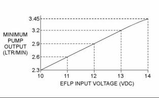
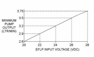
• For a 12 VDC system on a 1204E engine, refer to Illustration 31 for the minimum acceptable flow rate. |
|
g02525302 |
|
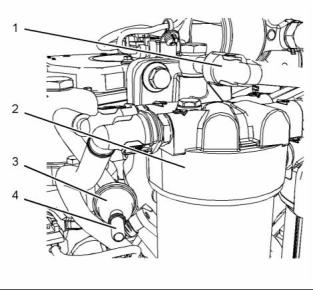
Illustration 29 |
|
Locations on the low-pressure fuel system on a 1204E engine |
|
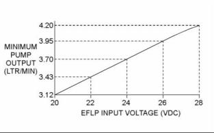
• For a 24 VDC system on a 1204E engine, refer to Illustration 32 for the minimum acceptable flow rate. |
|
(1) Fuel return to the secondary fuel filter (2) Secondary fuel filter base (3) Transfer pump inlet regulator (TPIR) (4) Transfer pump inlet regulator return port |
|
• For a 12 VDC system on a 1206E engine, refer to Illustration 33 for the minimum acceptable flow rate. |
|
• For a 24 VDC system on a 1206E engine, refer to Illustration 34 for the minimum acceptable flow rate. |
|
g02526956 |
|
Illustration 30 |
|
g02485896 |
|
Illustration 31 |
|
Locations on the low-pressure fuel system on a 1206E engine |
|
Minimum TPIR flow rate for a 1204E engine with a 12 VDC system |
|
(1) Fuel return to the secondary fuel filter (2) Secondary fuel filter base (3) Transfer pump inlet regulator (TPIR) (4) Transfer pump inlet regulator return port |
|
Transfer Pump Inlet Regulator (TPIR) Flow Test |
|
For a 1204E engine, refer to Illustration 29. For a 1206E engine, refer to Illustration 30. |
|
Perform the following procedure: |
|
This document is printed from SPI². Not for RESALE |
![]()
![]()

![]()
![]()
|
64 |
|
KENR9116-01 |
|
Troubleshooting Section |
|
Return Pressure Relief Valve Test |
|
Use the following procedure to check the fuel flow through the return pressure relief valve in the secondary fuel filter base: |
|
1. Disconnect the return line (1) from the secondary fuel filter base and install a blank on the line. Install a temporary line and a calibrated container to the filter base. |
|
2. With the keyswitch in the ON position, measure fuel flow from the temporary line. |
|
3. If the fuel flow is more than 300 mL/min (10.2 oz/min), replace the secondary fuel filter base. Refer to Disassembly and Assembly, “Fuel Filter Base - Remove and Install (Twin Secondary Fuel Filter)”. |
|
g02485897 |
|
Illustration 32 |
|
Minimum TPIR flow rate for a 1204E engine with a 24 VDC system |
|
4. Remove the temporary line and reconnect the return line. |
|
5. If the secondary fuel filter base has been replaced, attempt to start the engine. If the engine does not start, use the following procedure to check the fuel flow from the EFLP: |
|
6. Disconnect the fuel inlet from the primary fuel filter. Place the open end of the disconnected line into a calibrated container. |
|
g02355128 |
|
Illustration 33 |
|
7. With the keyswitch in the ON position, measure the flow from the fuel line. Refer to the Illustration 35 for the minimum acceptable fuel flow on a 12 VDC system. Refer to the Illustration 36 for the minimum acceptable fuel flow on a 24 VDC system. |
|
Minimum TPIR flow rate for a 1206E engine with a 12 VDC system |
|
g02355130 |
|
Illustration 34 |
|
Minimum TPIR flow rate for a 1206E engine with a 24 VDC system |
|
6. Remove the temporary drain line from the drain port on the TPIR. Connect the TPIR return line to the TPIR. |
|
g02527498 |
|
Illustration 35 |
|
Minimum EFLP flow rate for a 12 VDC system |
|
7. If the fuel flow in Step 5 is greater than the minimum limit, proceed to “Low Compression (Cylinder Pressure)”. |
|
8. If the fuel flow in Step 5 is below the minimum limit, proceed to “Return Pressure Relief Valve Test”. |
|
This document is printed from SPI². Not for RESALE |
![]()
![]()

![]()

![]()
![]()

|
KENR9116-01 |
|
65 Troubleshooting Section |
|
• Worn valves |
|
• Faulty cylinder head gasket |
|
• Damaged cylinder head |
|
3. Perform all necessary repairs. 4. Ensure that the repairs have eliminated the faults. |
|
5. If no faults are detected, proceed to “Electronic Unit Injectors”. |
|
Electronic Unit Injectors |
|
g02527518 |
|
Illustration 36 |
|
1. Use the electronic service tool to perform the automatic “Cylinder Cut Out Test”. If the compression test that was performed in “Low Compression (Cylinder Pressure)” was satisfactory, the “Cylinder Cut Out Test” will identify any faulty injectors. |
|
Minimum EFLP flow rate for a 24 VDC system |
|
8. If the fuel flow is more than 5% below the |
|
acceptable limit, replace the EFLP. |
|
9. If the fuel flow is more than 5% above the acceptable limit, contact Perkins Global Technical Support. |
|
2. Remove any faulty electronic unit injectors. Refer to Disassembly and Assembly, “Electronic Unit Injector - Remove”. |
|
10. If the fuel flow from the EFLP is within limits, |
proceed to “Check the Return Fuel Lines”.
|
3. Install new electronic unit injectors. Refer to Disassembly and Assembly, “Electronic Unit Injector - Install”. |
|
Check the Return Fuel Lines |
|
1. Make sure that the TPIR return line is not blocked or kinked. |
|
4. Repeat the test in 1. If the fault is still apparent, remove the replacement electronic unit injector and install the original electronic unit injector. Refer to Disassembly and Assembly, “Electronic Unit Injector - Remove” and Disassembly and Assembly, “Electronic Unit Injector - Install”. |
|
2. If the TPIR return line is clear, confirm that the Electric Fuel Lift Pump (EFLP) is operating. Make sure that fuel lines between the EFLP and the TPIR are not blocked or kinked. |
|
5. If the repair does not eliminate the fault, refer to “Individual Malfunctioning Cylinders”. |
|
3. If the fuel lines to the TPIR are clear and the EFLP is operating, replace the TPIR. |
|
Individual Malfunctioning Cylinders |
|
4. If the fault is still present, proceed to “Low |
|
Compression (Cylinder Pressure)”. |
|
1. With the engine speed at a fast idle, use the electronic service tool to perform the manual “Cylinder Cut Out Test”. As each cylinder is cut out, listen for a change in the sound from the engine. When a cylinder is cut out, there should be a noticeable change in the sound of the engine. If a change in the sound of the engine is not noted, the isolated cylinder is not operating under normal conditions. If the isolation of a cylinder results in a change that is less noticeable, the cylinder is operating below normal performance. Investigate the cause of the fault on any cylinder that is not operating. Investigate the cause of the fault on any cylinder that is operating below normal performance. |
|
Low Compression (Cylinder Pressure) |
|
1. Perform a compression test. Refer to Systems Operation, Testing and Adjusting, “Compression - Test ”. |
|
2. If low compression is noted on any cylinders, investigate the cause and rectify any faults. |
|
Possible causes of low compression are shown in the following list: |
|
• Loose glow plugs • Faulty piston |
|
2. If the fault is not eliminated, repeat this test |
|
procedure from Test Step 1. |
|
• Faulty piston rings • Worn cylinder bores |
|
This document is printed from SPI². Not for RESALE |
![]()
![]()
|
66 |
|
KENR9116-01 |
|
Troubleshooting Section |
|
i04079191 |
|
i04079192 |
|
Alternator Is Noisy |
|
Alternator Problem |
|
Refer to Systems Operation, Testing, and Adjusting for information on possible electrical causes of this condition. |
|
Probable Causes • Alternator drive belt • Charging circuit • Alternator |
|
Probable Causes • Alternator drive belt |
|
• Alternator mounting bracket • Alternator drive pulley • Alternator bearings |
|
Recommended Actions |
|
Alternator Drive Belt |
|
Inspect the condition of the alternator drive belt. If the alternator drive belt is worn or damaged, check that the drive belt for the alternator and the pulley are correctly aligned. If the alignment is correct, replace the drive belt. Refer to Disassembly and Assembly, “Alternator Belt - Remove and Install”. |
|
Charging Circuit |
|
Inspect the battery cables, wiring, and connections in the charging circuit. Clean all connections and tighten all connections. Replace any faulty parts. |
|
Alternator Mounting Bracket |
|
Alternator |
|
Inspect the alternator mounting bracket for cracks and wear. Repair the mounting bracket or replace the mounting bracket. Ensure that the alternator drive belt and the alternator drive pulley are in alignment. |
|
Verify that the alternator is operating correctly. Refer to Systems Operation, Testing, and Adjusting, “Alternator - Test”. The alternator is not a serviceable item. The alternator must be replaced if the alternator is not operating correctly. Refer to Disassembly and Assembly, “Alternator - Remove” and Disassembly and Assembly , “Alternator - Install”. |
|
Alternator Drive Pulley |
|
Remove the nut for the alternator drive pulley and then inspect the nut and the drive shaft. If no damage is found, install the nut and tighten the nut to the correct torque. Refer to Disassembly and Assembly, “Alternator - Install” for the correct torque. |
|
i04079193 |
|
Battery Problem |
|
Alternator Bearings |
|
Probable Causes • Charging circuit • Battery |
|
Check for excessive play of the shaft in the alternator. Check for wear in the alternator bearings. The alternator is a nonserviceable item. The alternator must be replaced if the bearings are worn. Refer to Disassembly and Assembly, “Alternator - Remove” and Disassembly and Assembly , “Alternator - Install”. |
|
• Auxiliary device |
|
This document is printed from SPI². Not for RESALE |
![]()
|
KENR9116-01 |
|
67 Troubleshooting Section |
|
Recommended Actions |
|
Cylinder Head Gasket |
|
Charging Circuit |
|
1. Remove the cylinder head. Refer to Disassembly and Assembly, “Cylinder Head - Remove” for the correct procedure. |
|
If a fault in the battery charging circuit is suspected, refer to Troubleshooting, “Alternator Problem”. |
|
2. Inspect the cylinder head gasket for faults and any |
|
signs of leakage. |
|
Faulty Battery |
|
3. Proceed to the recommended actions for the “Cylinder Head”. |
|
1. Check that the battery is able to maintain a charge. Refer to Systems Operation, Testing, and Adjusting, “Battery - Test”. |
|
Cylinder Head |
|
2. If the battery does not maintain a charge, replace the battery. Refer to the Operation and Maintenance Manual, “Battery - Replace”. |
|
1. Check the cylinder head for flatness. Refer to Systems Operation, Testing, and Adjusting, “Cylinder Head - Inspect” for the correct procedure. |
|
Auxiliary Device |
|
2. Check the mating face of the cylinder head for faults and signs of leakage. If a fault is found, replace the cylinder head. If signs of leakage are found, determine the cause of the leakage. Refer to Systems Operation, Testing, and Adjusting, “Cylinder Head - Inspect” for the correct procedure. |
|
1. Check if an auxiliary device has drained the battery by being left in the ON position. |
|
2. Charge the battery. |
|
3. Verify that the battery is able to maintain a charge |
|
when all auxiliary devices are switched off. |
|
3. Proceed to “Cylinder Block”. |
|
Cylinder Block |
|
i04079194 |
|
Coolant Contains Oil |
|
Inspect the top face of the cylinder block for faults and signs of leakage. If a fault is found, replace the cylinder block. If signs of leakage are found, determine the cause of the leakage. Refer to Systems Operation, Testing, and Adjusting, “Cylinder Block - Inspect” for the correct procedure. |
|
Probable Causes • Engine oil cooler • Cylinder head gasket • Cylinder head |
|
Assembly after Repair |
|
1. Install the cylinder head. Refer to Disassembly and Assembly, “Cylinder Head - Install”. |
|
• Cylinder block |
|
2. Replenish the engine with clean engine oil to the correct level. Refer to the Operation and Maintenance Manual, “Engine Oil and Filter - Change” for more information. |
|
Recommended Actions |
|
Engine Oil Cooler |
|
3. Fill the cooling system. Refer to the Operation and Maintenance Manual, “Cooling System Coolant (ELC) - Change”. |
|
1. Drain the coolant from the cooling system. Drain the lubricating oil from the engine oil cooler. Refer to the Operation and Maintenance Manual for more information. |
|
i03860850 |
|
Coolant Level Is Low |
|
2. Check for leaks in the oil cooler assembly. Refer to Systems Operation, Testing, and Adjusting, “Cooling System” for the correct procedure. If a leak is found, install a new oil cooler. Refer to Disassembly and Assembly, “Engine Oil Cooler - Remove” and Disassembly and Assembly, “Engine Oil Cooler - Install” for the correct procedure. |
|
This diagnostic trouble code is only applicable if the optional coolant level switch is installed. |
|
This procedure covers the following diagnostic code: |
|
This document is printed from SPI². Not for RESALE |
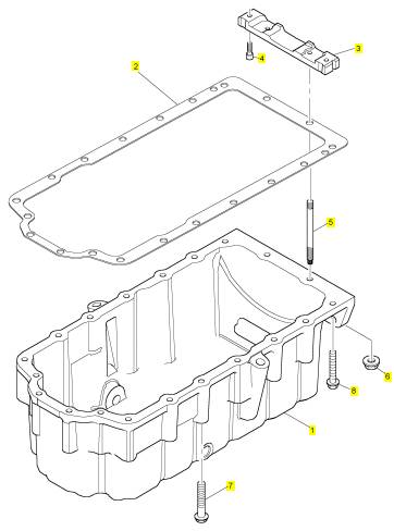
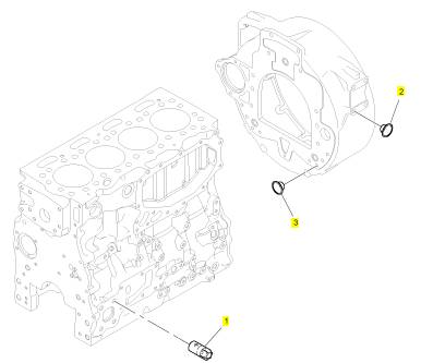
1 T408653 1 T408653 油底壳
2 3681 K037 1 3681 K037 密封垫片 -油底壳
3 T407009 1 T407009 气门
4 2311 D039 2 2311 D039 螺旋
5 3211 P013 2 3211 P013 图钉
6 2318 A603 2 2318 A603 螺帽
7 2314 H017 16 2314 H017 螺旋
8 2314 H004 2 2314 H004 螺旋
项目 零配件号码 新件号 描述
1 T405830 1 T405830 曲轴皮带轮
2 32186146 3 32186146 螺拴

项目 零配件号码 新件号 描述
1 2654407 1 2654407 滤油器

项目 零配件号码 新件号 描述
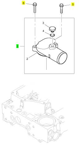
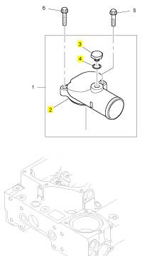
1 T414228 1 T414228 恒温节温器组合
1 T409197 1 T414228 恒温节温器组合
5 2314 H013 1 2314 H013 螺旋
6 2314 H005 2 2314 H005 螺旋
项目 零配件号码 新件号 描述
2 1 恒温节温器壳
3 T409183 1 T409183 栓塞
4 T409162 1 T409162 密封O型圈
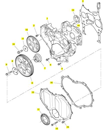
项目 零配件号码 新件号 描述
1 T405518 1 T405518 时间安排箱
2 T405410 1 T405410 密封垫片 - 正时齿轮箱
3 2314 H003 7 2314 H003 螺旋
4 2314 H006 2 2314 H006 螺拴
5 2314 H034 3 2314 H034 螺旋
6 T407065 1 T407065 惰轮传动机构
7 T416351 1 T416351 轮毂
7 T406834 1 T416351 轮毂
8 T406040 1 T406040 板
9 2314 J010 3 2314 J010 螺旋
10 T407464 1 T407464 凸轮轴传动机构
11 3321 A003 1 3321 A003 垫圈
12 2314 J606 1 2314 J606 螺旋
13 3112 X011 1 3112 X011 推力垫圈
14 2116053 1 2116053 合钉
15 T410624 1 T410624 正时齿轮盖
16 T406926 1 T406926 密封垫片 - 正时齿轮箱盖
17 T410666 1 T410666 密封 -前油封
18 2314 H003 9 2314 H003 螺旋
19 2314 H012 5 2314 H012 螺旋
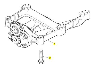
项目 零配件号码 新件号 描述
1 T407944 1 T407944 油泵
2 2314 J008 5 2314 J008 螺旋
项目 零配件号码 新件号 描述
1 T409980 4 T409980 喷油器
5 T406394 4 T406394 喷油器砂箱夹
6 3218 A016 4 3218 A016 螺旋
7 T407139 4 T407139 绑腿
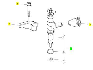
项目 零配件号码 新件号 描述
2 1 喷油器
3 T406053 1 T406053 密封O型圈
4 T405750 1 T405750 喷油器垫圈

项目 零配件号码 新件号 描述
1 T405402 1 T405402 启动马达
2 2313 C077 3 2313 C077 图钉
3 2318 A604 3 2318 A604 螺帽

项目 零配件号码 新件号 描述
1 T413421 1 T413421 水泵装备
10 2314 H006 3 2314 H006 螺拴
11 2314 K166 4 2314 K166 螺旋
12 T407489 1 T407489 连接
16 2314 F004 2 2314 F004 螺旋

项目 零配件号码 新件号 描述
2 1 水泵
9 T407626 1 T407626 密封垫片 - 水的泵

项目 零配件号码 新件号 描述
1 3212 V004 4 3212 V004 栓塞
2 2487207 4 2487207 栓塞
3 2487207 6 2487207 栓塞
项目 零配件号码 新件号 描述
1 T406408 1 T406408 风扇轮廓总成
2 3115 Y011 1 3115 Y011 风扇皮皮带轮
3 2314 J004 4 2314 J004 螺旋
4 3652970 1 3652970 皮带

项目 零配件号码 新件号 描述
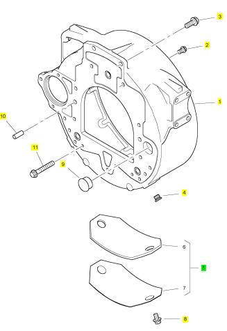
1 T405695 1 T405695 飞轮壳
2 2314 H030 2 2314 H030 螺旋
3 2314 J204 6 2314 J204 螺旋
4 T410815 2 T410815 栓塞
5 4148 K019 1 4148 K019 板
8 2314 J603 2 2314 J603 螺旋
9 2487 A452 1 2487 A452 栓塞
10 3245 A011 2 3245 A011 合钉
11 2314 J004 3 2314 J004 螺旋
项目 零配件号码 新件号 描述
1 T408625 1 T408625 凸轮轴
4 3142 V011 8 3142 V011 PUSHROD
4 T405746 8 3142 V011 PUSHROD
5 T411902 8 T411902 挺杆
5 T405810 8 T411902 挺杆

项目 零配件号码 新件号 描述
1 T405541 1 T405541 BUSBAR
2 T409125 4 T409125 GLOWPLUG
3 3881 A006 1 3881 A006 绝缘体
4 2318 A207 1 2318 A207 螺帽
5 2314 C038 1 2314 C038 螺旋
6 2487 F201 1 2487 F201 帽
项目 零配件号码 新件号 描述
1 T400052 1 T400052 引擎控制组件ECM电脑控制模块
2 T405430 4 T405430 间隔器
3 2634 C501 4 2634 C501 架设
4 3313 A027 4 3313 A027 间隔器
5 2634 C501 4 2634 C501 架设
6 T405497 2 T405497, 托架
7 2314 H008 4 2314 H008 螺旋
8 2131 A008 1 2131 A008 垫圈
9 CH12655 1 CH12655 盖
项目 零配件号码 新件号 描述
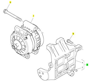
1 T405758 1 T405758 交流充电发电机
2 2314 J017 4 2314 J017 螺旋
3 T407399 1 T407399 交流充电发电机托架
6 2314 J005 4 2314 J005 螺旋
项目 零配件号码 新件号 描述
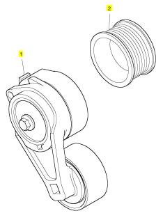
1 T411130 1 T411130 张紧轮
2 T407371 1 T407371 皮带轮
项目 零配件号码 新件号 描述
T406575 4 T407502 气门
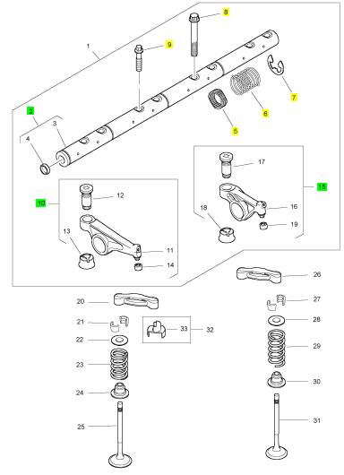
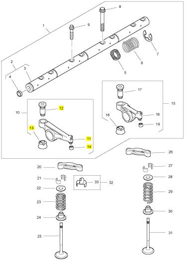
1 T407569 1 T407569 摇臂轴组合
20 T407502 4 T407502 气门
20 T406575 4 T407502 气门
21 3142 W003 8 3142 W003 阀筒夹
22 T406809 8 T406809 承件
23 T417714 8 T417714 阀弹簧
23 T407056 8 T417714 阀弹簧
24 T412573 8 T412573 气门油封
24 T407967 8 T407967 气门油封
25 T406777 8 T406777 进气门
26 T407502 4 T407502 气门
26 T406575 4 T407502 气门
27 3142 W003 8 3142 W003 阀筒夹
28 T406809 8 T406809 承件
29 T417519 8 T417519 阀弹簧
29 3174 A026 8 T417519 阀弹簧
30 T412573 8 T412573 气门油封
30 T407967 8 T407967 气门油封
31 T405211 8 T405211 排气阀
32 T416277 1 T416277 承件

项目 零配件号码 新件号 描述
2 T406591 1 T406591 摇臂轴组合
5 3174 A024 1 3174 A024 摇臂轴弹簧
6 T407095 3 T407095 摇臂轴弹簧
7 2727 A015 4 2727 A015 CIRCLIP
8 2316 A901 1 2316 A901 螺旋
9 T406016 7 T406016 螺拴
10 T407570 4 T407570 摇臂组合
15 T406261 4 T406261 摇臂组合
项目 零配件号码 新件号 描述
11 1 摇臂
12 T407571 1 T407571 摇臂气门调整
13 T406029 1 T406029 导入
14 1 碗
项目 零配件号码 新件号 描述
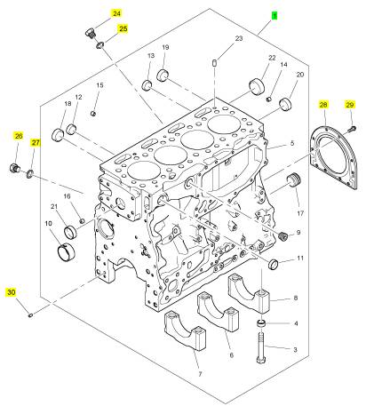
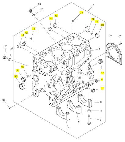
1 1 缸体组合
24 3278 A006 1 3278 A006 栓塞
25 2415 H519 1 2415 H519 密封O型圈
26 3278 A006 1 3278 A006 栓塞
27 2415 H003 1 2415 H003 密封O型圈
28 2418 F704 1 2418 F704 密封 - 再操作系统壳
29 3211 C002 10 3211 C002 公制的螺拴
30 0350010 1 0350010 合钉
项目 零配件号码 新件号 描述
2 1 缸体组合
9 0650588 1 0650588 栓塞
10 T410164 1 T410164 凸轮轴衬套
11 0650710 1 0650710 栓塞
12 0650710 1 0650710 栓塞
13 0650710 1 0650710 栓塞
14 2485 A309 1 2485 A309 栓塞
15 2485 A309 1 2485 A309 栓塞
16 2485 A309 1 2485 A309 栓塞
17 3212 P008 1 3212 P008 栓塞
18 3241 A011 1 3241 A011 栓塞
19 3241 A011 1 3241 A011 栓塞
20 3241 A011 1 3241 A011 栓塞
21 3241 A011 1 3241 A011 栓塞
22 3241 A012 1 3241 A012 栓塞
23 3244 A009 2 3244 A009 合钉
项目 零配件号码 新件号 描述
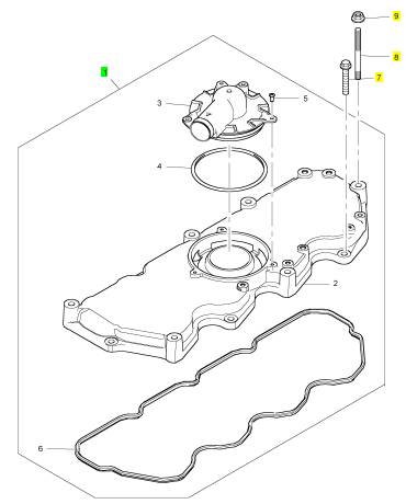
1 T408342 1 T408342 CYL 座盖 ASSY
7 2314 H004 5 2314 H004 螺旋
8 T412761 6 T412761 图钉
8 2313 H245 6 2313 H245 图钉
9 2318 A603 6 2318 A603 螺帽
项目 零配件号码 新件号 描述
2 1 汽缸盖盖
3 T406923 1 T406923 帽
4 1 密封O型圈
5 2152 A034 3 2152 A034 螺旋
6 T400093 1 T400093 密封

项目 零配件号码 新件号 描述
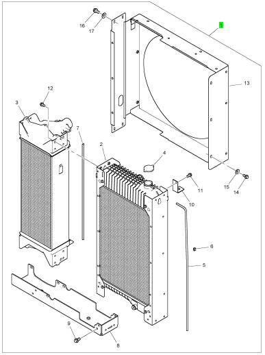
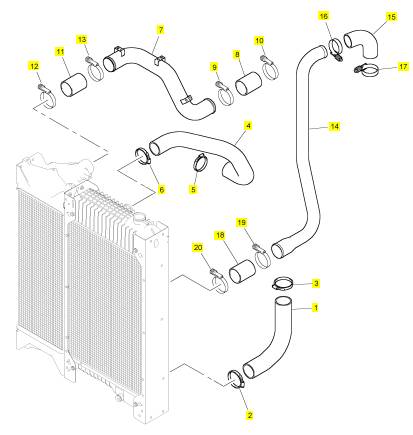
1 T409957 1 T409957 散热器
项目 零配件号码 新件号 描述
1 T410366 1 T410366 水管 -冷却器
2 21825194 1 21825194 夹
2 2481 D074 1 2481 D074 水管夹
3 21825194 1 21825194 夹
3 2481 D074 1 2481 D074 水管夹
4 T410369 1 T410369 水管 -冷却器
5 21825194 1 21825194 夹
5 2481 D074 1 2481 D074 水管夹
6 21825194 1 21825194 夹
6 2481 D074 1 2481 D074 水管夹
7 T409672 1 T409672 水管 -空气
8 T408187 1 T408187 水管 -空气
9 T411155 1 T411155 水管夹
10 T411155 1 T411155 水管夹
11 T408187 1 T408187 水管 -空气
12 T411155 1 T411155 水管夹
13 T411155 1 T411155 水管夹
14 T411384 1 T411384 水管 -空气
15 T409696 1 T409696 水管 -空气
16 T411491 1 T411491 砂箱夹
17 T411491 1 T411491 砂箱夹
18 T408187 1 T408187 水管 -空气
19 T411155 1 T411155 水管夹
20 T411155 1 T411155 水管夹
项目 零配件号码 新件号 描述
1 1 汽缸盖组合
10 T412814 1 T412814 密封垫片 - 汽缸盖
10 T406619 1 T412814 密封垫片 - 汽缸盖
(10) T414453 1 T414453 密封垫片 - 汽缸盖
(10) T414454 1 T414454 密封垫片 - 汽缸盖
11 3218 A017 8 3218 A017 汽缸盖螺拴
12 3278 A006 1 3278 A006 栓塞
12 T412814 1 T412814 密封垫片 - 汽缸盖
12 T406619 1 T412814 密封垫片 - 汽缸盖
(12) T414453 1 T414453 密封垫片 - 汽缸盖
(12) T414454 1 T414454 密封垫片 - 汽缸盖
13 2415 H003 1 2415 H003 密封O型圈
13 3218 A017 8 3218 A017 汽缸盖螺拴
14 3278 A006 1 3278 A006 栓塞
15 2415 H003 1 2415 H003 密封O型圈
16 2485 A307 1 2485 A307 栓塞
16 3278 A006 1 3278 A006 栓塞
17 2415 H003 1 2415 H003 密封O型圈
18 2485 A307 1 2485 A307 栓塞
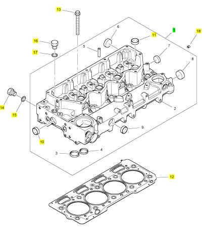
项目 零配件号码 新件号 描述
2 1 汽缸盖
3 T407000 8 T407000 气门座圈
4 T406545 8 T406545 气门座圈
5 T407959 16 T407959 气门导管
6 2485 A519 8 2485 A519 栓塞
7 2485 A519 1 2485 A519 栓塞
8 2485 A524 1 2485 A524 栓塞
9 2485 A524 1 2485 A524 栓塞
10 2485 A524 1 2485 A524 栓塞
11 2485 A517 4 2485 A517 栓塞

项目 零配件号码 新件号 描述
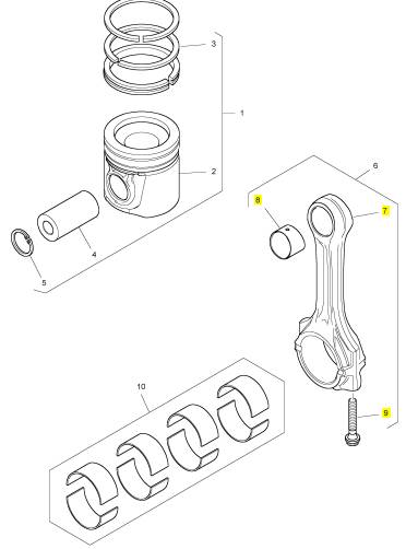
1 T410925 4 T410925 活塞及圈装备
(1) T400435 4 T400435 活塞及圈装备 -O/S
(1) T400436 4 T400436 活塞及圈装备 -O/S
6 T405102 4 T405102 连杆组合
10 T410927 1 T410927 大头轴承装备
(10) T420153 1 T420153 大头 BRG 装备 -U/S
(10) T420154 1 T420154 大头 BRG 装备 -U/S
(10) T420155 1 T420155 大头 BRG 装备 -U/S

项目 零配件号码 新件号 描述
2 1 活塞及圈装备
6 2721332 2 2721332 CIRCLIP /S

项目 零配件号码 新件号 描述
7 1 连杆
8 3112 E031 1 3112 E031 连杆小的一端衬套
9 T400001 2 T400001 连杆螺拴
项目 零配件号码 新件号 描述
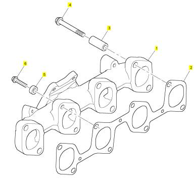
1 T408960 1 T408960 排气岐管
2 T407220 1 T407220 密封垫片
3 T405957 7 T405957 间隔器
4 3218 J025 7 3218 J025 螺旋
5 T407523 1 T407523 间隔器
6 3218 A018 1 3218 A018 螺旋
项目 零配件号码 新件号 描述
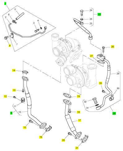
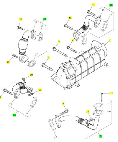
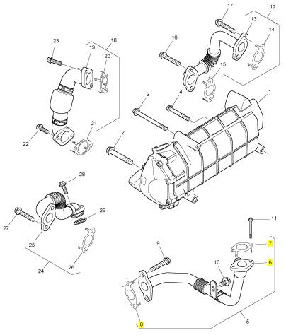
1 T409045 1 T409045 管 -推进
8 2314 H002 1 2314 H002 螺旋
9 T408933 1 T408933 管 - 涡轮增压器的油排泄
12 2314 H002 1 2314 H002 螺旋
13 2314 H003 2 2314 H003 螺旋
14 T408054 1 T408054 密封垫片
15 2314 F004 2 2314 F004 螺旋
16 T407852 1 T407852 密封垫片
17 T408948 1 T408948 管 - 涡轮增压器的油排泄
18 2314 H003 2 2314 H003 螺旋
19 CH11561 1 CH11561 密封垫片
20 2314 H003 2 2314 H003 螺旋
21 T408054 1 T408054 密封垫片
22 T408935 1 T408935 管 - 涡轮增压器的油补给
26 2314 H005 2 2314 H005 螺旋
27 CH12205 1 CH12205 密封垫片
28 T408941 1 T408941 管 - 涡轮增压器的油补给
33 2314 H002 1 2314 H002 螺旋
项目 零配件号码 新件号 描述
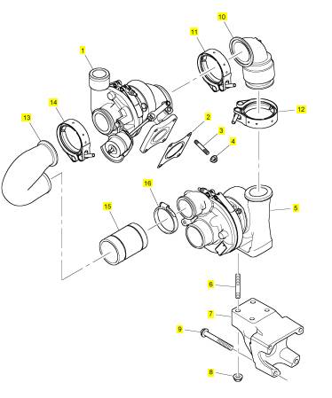
1 T413586 1 T413586 涡轮增压器
1 T409033 1 T413586 涡轮增压器
2 T407547 1 T407547 密封垫片 -涡轮增压器
3 2313 M359 4 2313 M359 图钉
4 2318 A633 4 2318 A633 螺帽
5 T414287 1 T414287 涡轮增压器
5 T409029 1 T414287 涡轮增压器
5 T413587 1 T414287 涡轮增压器
6 2313 M383 4 2313 M383 图钉
7 T409003 1 T409003 托架
8 2318 A634 4 2318 A634 螺帽
9 2314 J013 4 2314 J013 螺旋
10 T407900 1 T407900 排气肘管
11 T406192 1 T406192 砂箱夹
12 T407169 1 T407169 砂箱夹
13 T409032 1 T409032 导气管
14 T407169 1 T407169 砂箱夹 , ;
15 T407961 1 T407961 水管
16 2481 D075 2 2481 D075 水管夹
项目 零配件号码 新件号 描述
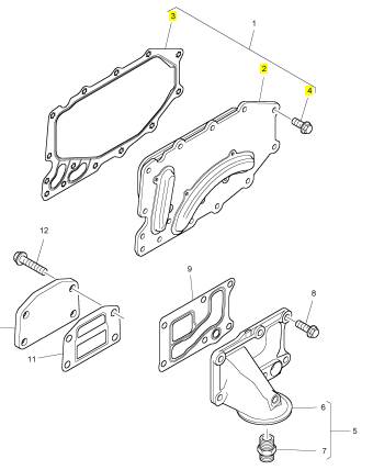
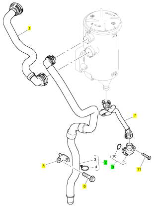
1 T408482 1 T408482 机油冷油器
5 T408200 1 T408200 滤油器座
8 2314 H034 5 2314 H034 螺旋
9 T405475 1 T405475 密封垫片
10 3623 A009 1 3623 A009 切片板
11 3688 A039 1 3688 A039 密封垫片 - 滤油器的座
12 2314 H033 4 2314 H033 螺旋
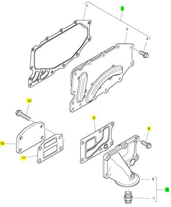
项目 零配件号码 新件号 描述
2 1 机油冷油器
3 T408424 1 T408424 密封垫片
4 2314 H003 14 2314 H003 螺旋
项目 零配件号码 新件号 描述
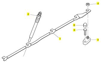
1 T405903 1 T405903 管 -呼吸者
2 T408467 1 T408467 管 -呼吸者
5 T418357 1 T418357 托架
5 T408475 1 T418357 托架
6 2314 H607 1 2314 H607 螺旋
7 T417595 1 T417595 管 -呼吸者
7 T407195 1 T417595 管 -呼吸者
8 T407957 1 T407957 停机电磁阀
11 2314 H033 1 2314 H033 螺旋
项目 零配件号码 新件号 描述
1 T411307 1 T411307 冷却器
2 2314 H010 1 2314 H010 螺旋
3 2314 H017 1 2314 H017 螺旋
4 2314 K161 1 2314 K161 螺旋
5 T411298 1 T411298 水管 -空气
9 2314 H004 2 2314 H004 螺旋
10 2314 H001 1 2314 H001 螺旋
11 2314 F016 2 2314 F016 螺旋
12 T411330 1 T411330 水管 -冷却器
16 2314 H004 2 2314 H004 螺旋
17 2314 H004 2 2314 H004 螺旋
18 T417289 1 T417289 水管 -空气
18 T411045 1 T417289 水管 -空气
18 T414020 1 T417289 水管 -空气
22 T411589 2 T411589 螺拴
23 T411589 2 T411589 螺拴
24 T411334 1 T411334 水管 -冷却器
27 2314 H004 2 2314 H004 螺旋
28 2314 H004 1 2314 H004 螺旋
29 T409092 1 T409092 密封O型圈
项目 零配件号码 新件号 描述
6 1 水管 -空气
7 T409208 1 T409208 密封垫片
8 T409207 1 T409207 密封垫片
项目 零配件号码 新件号 描述
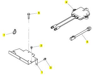
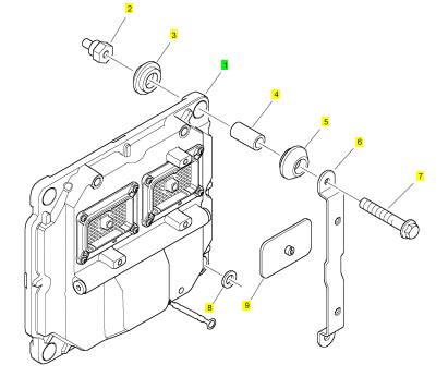
1 T408882 1 T408882 托架
2 2314 J002 2 2314 J002 螺旋
3 2314 H002 2 2314 H002 螺旋
4 T419733 1 T419733 控制砂箱
4 T409881 1 检查历史 控制砂箱
4 T412571 1 检查历史 控制砂箱
5 T419731 1 T419731 线束
6 2314 F006 2 2314 F006 螺旋
7 2817152 1 2817152 缆拉杆
8 T409393 9 T409393 缆拉杆