 English
 Espaol
 Franais
 阿拉伯
阿拉伯 中文
中文 Deutsch
 Italiano
 Português
 日本
日本 韩国
韩国 български
 hrvatski
 esky
esky Dansk
Dansk Nederlands
 suomi
suomi Ελληνικ
 印度
印度 norsk
norsk Polski
 Roman
Roman русский
 Svenska
Perkins1204柴油发动机高压燃油泵配件供应商,Perkins1204柴油发动机高压燃油泵配件技术价格规格咨询服务,Perkins1204柴油发动机高压燃油泵配件零配件供应,Perkins1204柴油发动机高压燃油泵配件售后服务中心,Perkins1204柴油发动机高压燃油泵配件,Perkins1204柴油发动机高压燃油泵配件详细的技术参数,

Perkins1204柴油发动机高压燃油泵配件
详细描述
项目 零配件号码 新件号 描述
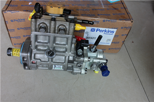
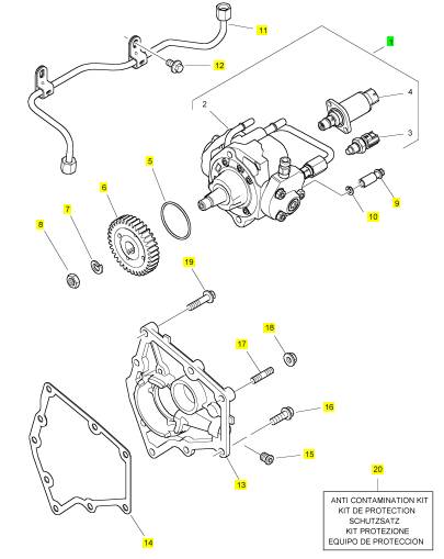
1 T410424 1 T410424 高压燃油泵
5 T405938 1 T405938 密封O型圈
6 T406014 1 T406014 燃油喷射泵传动机构
7 K134AF01 1 K134AF01 垫圈
8 2318 A108 1 2318 A108 螺帽
9 2316 A317 2 2316 A317 螺旋
10 2134 A008 2 2134 A008 垫圈
11 T414016 1 T414016 管 - 高的压力燃油
11 T407755 1 T414016 管 - 高的压力燃油
12 2314 H031 2 2314 H031 螺旋
13 T405858 1 T405858 板
13 T405760 1 T405858 板
14 T406721 1 T406721 密封垫片 - 燃油的 INJ 泵
15 2487 A208 1 2487 A208 栓塞
16 2314 H034 2 2314 H034 螺旋
17 2313 M060 2 2313 M060 图钉
18 2318 A603 2 2318 A603 螺帽
19 2314 H036 4 2314 H036 螺旋
20 T410437 1 T410437 保护装备
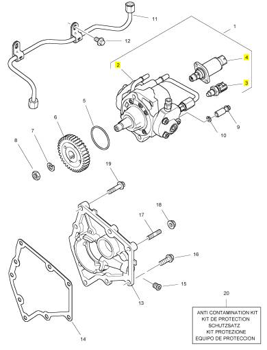
项目 零配件号码 新件号 描述
2 1 高压燃油泵
3 T405451 1 T405451 温度感应传感器
4 T408502 1 T408502 阀
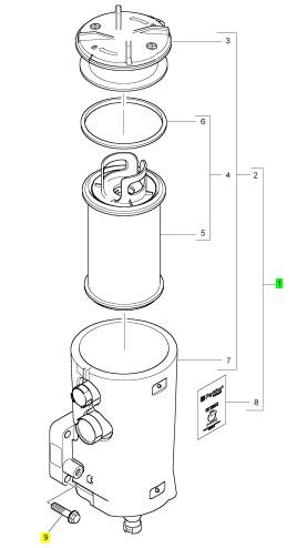
项目 零配件号码 新件号 描述
1 3612890 1 3612890 呼吸者
1 3612890 1 3612890 呼吸者
9 2314 H006 3 2314 H006 螺拴
项目 零配件号码 新件号 描述
2 1 呼吸者
2 3524146 1 3524146 呼吸者机械要素装备
8 1 标签
项目 零配件号码 新件号 描述
1 T418032 1 T418032 托架
1 T410420 1 检查历史 托架
1 T410420 1 检查历史 托架
1 T412861 1 检查历史 托架
2 2152 B056 4 2152 B056 螺旋
2 2152 B056 4 2152 B056 螺旋
2 T412372 4 T412372 螺旋
3 T405054 1 T405054 感应传感器
4 2415 H001 1 2415 H001 密封O型圈
5 T410429 1 T410429 管
6 T408546 1 T408546 管套节
7 2415 H002 1 2415 H002 密封O型圈
8 T412841 1 T412841 托架
8 T410425 1 T412841 托架
9 2314 H007 2 2314 H007 螺旋
10 T405054 1 T405054 感应传感器
11 2415 H001 1 2415 H001 密封O型圈
12 T411789 1 T411789 管
12 T410426 1 T411789 管
13 T408546 1 T408546 管套节
14 2415 H002 1 2415 H002 密封O型圈
15 T407268 1 T407268 温度感应传感器
16 2817152 3 2817152 缆拉杆
项目 零配件号码 新件号 描述
1 T407180 1 T407180 感应传感器
2 2415 H001 1 2415 H001 密封O型圈
3 T407354 1 T407354 温度感应传感器
4 2415 H519 1 2415 H519 密封O型圈
5 T407354 1 T407354 温度感应传感器
6 2415 H003 1 2415 H003 密封O型圈
7 1 速度感应传感器
8 CH12649 1 CH12649 密封O型圈
8 2415 H014 1 2415 H014 密封O型圈
9 2314 H002 1 2314 H002 螺旋
10 1 速度感应传感器
11 CH12649 1 CH12649 密封O型圈
11 2415 H014 1 2415 H014 密封O型圈
12 2314 H002 1 2314 H002 螺旋
13 T406711 1 T406711 感应传感器
14 2415 H002 1 2415 H002 密封O型圈
15 T407269 1 T407269 气压感应传感器
项目 零配件号码 新件号 描述
3712809 1 4520333 燃油过滤器组合
1 3712807 1 3712807 燃油过滤器组合
1 3712807 1 3712807 燃油过滤器组合
1 3712807 1 3712807 燃油过滤器组合
13 T410437 1 T410437 保护装备
项目 零配件号码 新件号 描述
14 1 燃油过滤器座
15 T410737 1 T410737 栓塞
18 3611272 1 3611272 燃油过滤器组合
|
KENR9116-01 |
|
31 Troubleshooting Section |
|
Clean Emissions Module (CEM) |
|
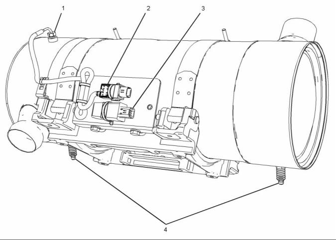
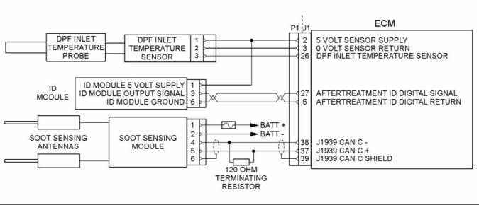
g02095035 |
|
Illustration 18 |
|
Sensors and components on a typical CEM |
|
(1) Temperature probe for the inlet to the DPF |
|
(2) Inlet temperature sensor (3) Aftertreatment identification module |
|
(4) Soot antennas |
|
i04319697 |
|
Table 5 |
|
Engine Wiring Information |
|
Color Codes for the Harness Wire |
|
Color Code |
|
Color |
|
Color Code |
|
Color |
|
BK BR RD OR YL |
|
Black |
|
BU PU GY WH PK |
|
Blue |
|
Harness Wire Identification |
|
Brown Red |
|
Purple Gray |
|
Perkins identifies all wires with 11 solid colors. The circuit number is stamped on the wire at a 25 mm (1 inch) spacing. Table 5 lists the wire colors and the color codes. |
|
Orange Yellow Green |
|
White Pink |
|
GN |
|
For example, a wire identification of F730-OR on the schematic would signify an orange wire with the circuit number F730. F730-OR identifies the power supply for the oil pressure sensor. |
|
Note: Always replace a harness wire with the same gauge of wire and with the same color code. This document is printed from SPI². Not for RESALE |
![]()
![]()

|
32 |
|
KENR9116-01 |
|
Troubleshooting Section |
|
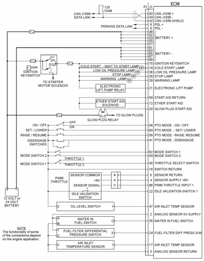
Note: In the following diagrams, “Pxxx” signifies a plug and “Jxxx” signifies a jack. |
|
Schematic Diagrams |
|
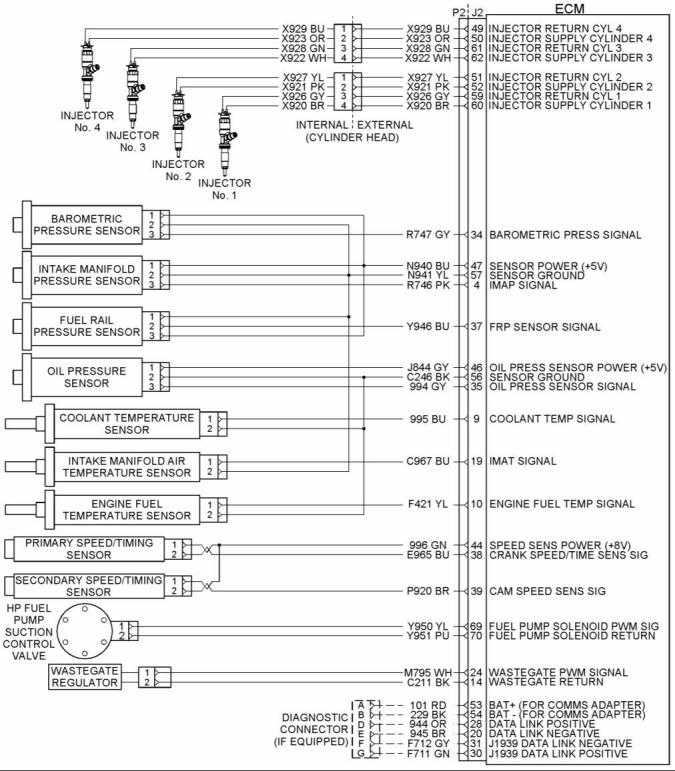
1204E-E44 Engine |
|
g02101233 |
|
Illustration 19 |
|
Schematic diagram of the 1204E-E44 engine connections to the J2 connector on the ECM |
|
This document is printed from SPI². Not for RESALE |
![]()
![]()
|
KENR9116-01 |
|
33 Troubleshooting Section |
|
1206E-E66 Engine |
|
g02101353 |
|
Illustration 20 |
|
Schematic diagram of the 1206E-E66 engine connections to the J2 connector on the ECM |
|
This document is printed from SPI². Not for RESALE |
![]()
![]()

|
34 |
|
KENR9116-01 |
|
Troubleshooting Section |
|
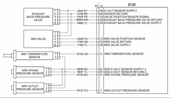
NOx Reduction System (NRS) |
|
g02101473 |
|
Illustration 21 |
|
Schematic diagram of the NRS equipment for the 1204E-E44 and 1206E-E66 engines |
|
Clean Emissions Module (CEM) |
|
g02554116 |
|
Illustration 22 |
|
Schematic diagram of the Clean Emissions Module (CEM) |
|
Wiring for the Application |
|
This document is printed from SPI². Not for RESALE |
![]()
![]()
![]()
|
KENR9116-01 |
|
35 Troubleshooting Section |
|
g02488496 |
|
Illustration 23 |
|
Schematic Diagram for a Typical Application |
|
This document is printed from SPI². Not for RESALE |
![]()
![]()
|
36 |
|
KENR9116-01 |
|
Troubleshooting Section |
|
i04021101 |
|
2. Position Tooling (A) around wire (2). |
|
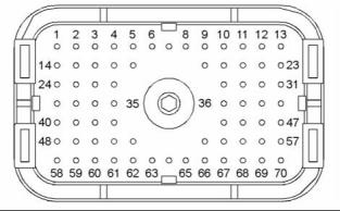
ECM Harness Connector Terminals |
|
Note: Make sure that the tool stays perpendicular to the face of the connector (1). |
|
3. Push the tool into the hole for the terminal. Gently pull the wire in order to remove the terminal from the rear of the connector (1). |
|
The Electronic Control Module (ECM) uses |
|
connectors that have 70 terminals to interface to the wiring harness. |
|
4. Remove the Tooling (A) from the wire. |
|
Note: If a terminal must be replaced, part number 2900A016 must be used for 16 and 18 AWG wire. Part number 28170024 must be used for 14 AWG wire. |
|
Terminal Insertion |
|
1. Push the terminal into the rear of the connector (1) until the terminal engages with the locking device. |
|
2. Gently pull on the wire (2) in order to make sure that the terminal is retained by the locking device. |
|
3. Connect the connector to the ECM and then tighten the retaining screw to a torque of 6 N·m (53 lb in). |
|
g01877659 |
|
Illustration 24 |
|
Layout of the Connector Pins (view from the rear) |
|
Removal and Installation of the Harness Connector Terminals |
|
Terminal Removal |
|
Table 6 |
|
Required Tools Part |
|
Tool A |
|
Part Description |
|
Qty |
|
Number |
|
2900A019 |
|
Removal Tool (Red) |
|
1 |
|
g01877813 |
|
Illustration 25 Removal Tool |
|
1. Remove the connector from the ECM. Refer to Disassembly and Assembly, “Electronic Control Module - Remove and Install”. |
|
This document is printed from SPI². Not for RESALE |
![]()
![]()
![]()
|
KENR9116-01 |
|
37 Troubleshooting Section |
|
Programming Parameters |
|
Note: “Test ECM Mode” can only be activated if the engine serial number has not already been programmed during normal operation of the ECM. If the engine serial number is programmed and the ECM is not in “Test ECM Mode”, the ECM can never be used as a test ECM. |
|
i03939853 |
|
Programming Parameters |
|
6. Use the “Copy Configuration” feature on the |
|
electronic service tool to program the test ECM. |
|
The electronic service tool can be used to view certain parameters that can affect the operation of the engine. The electronic service tool can also be used to change certain parameters. The parameters are stored in the Electronic Control Module (ECM). Some of the parameters are protected from unauthorized changes by passwords. Parameters that can be changed have a tattletale number. The tattletale number is incremented whenever a parameter is changed. |
|
Note: If the “ECM Replacement” feature cannot be used, program the test ECM with the values from the “Customer Specified Parameters Worksheet” and the values from the System Configuration Parameters. |
|
7. Program the engine serial number into the test ECM. |
|
Note: The “Test ECM Mode” must be activated before the engine serial number is programmed into the ECM. |
|
i03939990 |
|
Test ECM Mode |
|
8. Verify that the test ECM eliminates the fault. |
|
When the “Test ECM Mode” is activated, an internal timer sets a 24 hour clock. This clock will count down only while the ECM is powered and the keyswitch is in the ON position. After the ECM has counted down the 24 hour period, the ECM will exit the “Test ECM Mode”. The parameters and the engine serial number will be set. |
|
“Test ECM Mode” is a feature in the software that can be used to help troubleshoot an engine that may have a fault in the Electronic Control Module (ECM). This feature allows a standard ECM to be used as a test ECM. This feature eliminates the need to stock a test ECM. |
|
If the test ECM eliminates the fault, the engine can be released while the “Test ECM Mode” is still active. |
|
1. Search for the latest flash file for the engine. |
|
Once an ECM has been activated in the “Test ECM Mode”, the ECM will stay in the “Test ECM Mode” until the timer times out. If the ECM is used as a test ECM for more than one engine, the “Test ECM Mode” must be reactivated. Anytime prior to the “Test ECM Mode” timing out, the ECM can be reset to 24 hours. |
|
Note: If a newer software version is available for the engine, install the newest software on the suspect ECM. If the new software does not eliminate the fault, continue with this procedure. |
|
2. Use the “Copy Configuration” feature on the electronic service tool to copy the parameters from the suspect ECM. |
|
i03898736 |
|
Factory Passwords |
|
Note: If the “ECM Replacement” feature cannot be used, record the programmed values into the “Customer Specified Parameters Worksheet”. Also record the system configuration parameters. |
|
NOTICE |
|
3. Disconnect the suspect ECM. Temporarily connect the test ECM to the engine. Do not mount the test ECM on the engine. |
|
Operating the engine with a flash file not designed for that engine will damage the engine. Be sure the flash file is correct for your engine. |
|
4. Flash program the test ECM with the newest |
|
software that is available. |
|
Note: Factory passwords are provided only to |
|
Perkins authorized distributors. |
|
5. Start the “Test ECM Mode” on the electronic service tool. Access the feature through the “Service” menu. The electronic service tool will display the status of the test ECM and the hours that are remaining for the “Test ECM Mode”. |
|
Factory passwords are required to perform each of the following functions: |
|
This document is printed from SPI². Not for RESALE |
![]()
![]()
![]()
|
38 |
|
KENR9116-01 |
|
Troubleshooting Section |
|
• Program a new Electronic Control Module (ECM). |
|
Note: You must have the engine serial number in order to search for the part number of the flash file. |
|
When an ECM is replaced, the system configuration parameters must be programmed into the new ECM. A new ECM will allow these parameters to be programmed once without factory passwords. After the initial programming, some parameters are protected by factory passwords. |
|
2. Connect the electronic service tool to the diagnostic connector. |
|
3. Turn the keyswitch to the ON position. Do not start the engine. |
|
4. Select “WinFlash” from the “Utilities” menu on the |
|
• Rerate the engine. |
|
electronic service tool. |
|
Rerating may require changing the interlock code, which is protected by factory passwords. |
|
Note: If WinFlash will not communicate with the ECM, refer to Troubleshooting, “Electronic Service Tool Will Not Communicate with ECM”. |
|
• Unlock parameters. |
|
5. Flash program the flash file into the ECM. |
|
Factory passwords are required in order to unlock certain system configuration parameters. Refer to Troubleshooting, “System Configuration Parameters”. |
|
a. Select the engine ECM under the “Detected ECMs”. |
|
b. Press the “Browse” button in order to select the part number of the flash file that will be programmed into the ECM. |
|
• Clear engine events and certain diagnostic codes. |
|
Most engine events require factory passwords in order to clear the code from ECM memory. Clear these codes only when you are certain that the fault has been corrected. For example, the 190-15 Engine Overspeed requires the use of factory passwords in order to clear the code from ECM memory. |
|
c. When the correct flash file is selected, press the “Open” button. |
|
d. Verify that the “File Values” match the application. If the file values do not match the application, search for the correct flash file. |
|
e. When the correct flash file is selected, press the “Begin Flash” button. |
|
Since factory passwords contain alphabetic |
|
characters, the electronic service tool must be used to perform these functions. In order to obtain factory passwords, proceed as if you already have the password. If factory passwords are needed, the electronic service tool will request the factory passwords. The electronic service tool will display the information that is required to obtain the passwords. |
|
f. The electronic service tool will indicate when the flash programming has been successfully completed. |
|
6. Use the electronic service tool to check for diagnostic code 631-2. If this diagnostic code is active and the flash file is not being installed in order to change the engine rating, repeat this procedure from 1. If this diagnostic code is active and the flash file is being installed in order to change the engine rating, factory passwords must be obtained. |
|
i03898779 |
|
Flash Programming |
|
7. Access the “Configuration” screen under the “Service” menu in order to determine the parameters that require programming. Look under the “Tattletale” column. All of the parameters should have a tattletale of 1 or more. If a parameter has a tattletale of 0, program that parameter. |
|
Flash Programming – A method of loading a flash file into the Electronic Control Module (ECM) |
|
The electronic service tool is utilized to flash program a flash file into the ECM. The flash programming transfers the flash file from the PC to the ECM. |
|
8. Start the engine and check for proper operation. Check that there are no active diagnostic codes. |
|
Flash Programming a Flash File |
|
1. Obtain the part number for the new flash file. |
|
Note: If you do not have the part number for the flash file, use PTMI on the Perkins web site. |
|
This document is printed from SPI². Not for RESALE |
![]()
|
KENR9116-01 |
|
39 Troubleshooting Section |
|
“WinFlash” Error Messages |
|
If any error messages are displayed during flash programming, click on the “Cancel” button in order to stop the process. Access the “ECM Summary” information through the “Information” menu. Ensure that you are programming the correct flash file for your engine. |
|
If a 630-2 diagnostic trouble code is displayed after flash programming, a required parameter is missing. Program the missing parameter. |
|
i03859293 |
|
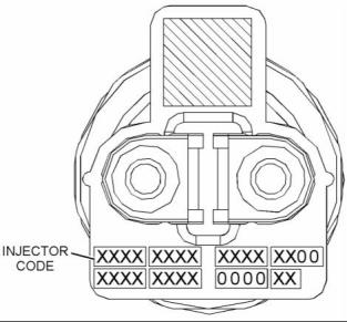
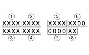
g02132457 |
|
Injector Code - Calibrate |
|
Illustration 27 |
|
Sequence for recording the injector code |
|
The electronic service tool is used to load the injector codes into the ECM. |
|
Injector codes are codes that are 30 hexadecimal characters in length that are supplied with each injector. The code is on a plate on the top of the injector and a card is also included in the packaging for the injector. The code is used by the Electronic Control Module (ECM) to balance the performance of the injectors. |
|
The injector codes must be loaded into the ECM if any of the following conditions occur: |
|
• An electronic unit injector is replaced. • The ECM is replaced. |
|
• Diagnostic code 268-2 is active. |
|
• Electronic unit injectors are exchanged between cylinders. |
|
Note: Diagnostic code 268-2 will also become active if the engine serial number, FLS or FTS are not entered into the ECM. |
|
If the ECM is replaced, the injector codes are normally transferred to the new ECM as part of the “Copy Configuration” procedure. If the “Copy Configuration” procedure fails, the injector codes must be loaded manually. |
|
Installing Injector Codes |
|
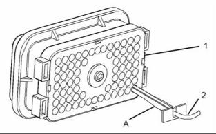
Note: The injector code is located on the electronic unit injector. |
|
g02132456 |
|
1. Record the injector code for each electronic unit |
|
Illustration 26 |
|
injector. |
|
Typical label with an injector code |
|
2. Connect the electronic service tool to the diagnostic connector. Refer to Troubleshooting, “Electronic Service Tools”. |
|
3. Turn the keyswitch to the ON position. |
|
4. Select the following menu options on the electronic service tool: |
|
• Service |
|
• Calibrations This document is printed from SPI². Not for RESALE |
![]()
![]()
![]()
|
40 |
|
KENR9116-01 |
|
Troubleshooting Section |
|
Mode Selection Number |
|
• Injector Trim Calibration 5. Select the appropriate cylinder. 6. Click on the “Change” button. |
|
This parameter is a non-programmable parameter that represents the number of possible combinations of switch positions. This parameter is based on the value that is programmed into the “Number of Switch Inputs” parameter. |
|
7. Input the applicable injector code that was |
|
recorded in Test Step 1. |
|
Mode Selection Switch Input 2 and Mode Selection Switch Input 1 |
|
8. Click on the “OK” button. |
|
The injector code is loaded into the ECM. |
|
The number of these non-programmable parameters that are visible depends on the value that is programmed into the “Number of Switch Inputs” parameter. “Open” signifies that the switch is in the OFF position. “Ground” signifies that the switch is in the ON position. |
|
9. Repeat the procedure for each cylinder, as required. |
|
Exchanging Electronic Unit Injectors |
|
Exchanging electronic unit injectors can help determine if a combustion problem is in the electronic unit injector or in the cylinder. If two electronic unit injectors that are currently installed in the engine are exchanged between cylinders, the injector codes must also be exchanged. Press the “Exchange” button at the bottom of the “Injector Trim Calibration” screen on the electronic service tool. Select the two electronic unit injectors that will be exchanged and press the “OK” button. The tattletale for the electronic unit injectors that were exchanged will increase by one. |
|
Rating Enabled |
|
If “Yes” is selected on the drop-down menu, the ECM is programmed to use the values in the “Rating Number”, “Throttle 1 Droop Percentage”, “Throttle 2 Droop Percentage” and “TSC1 Droop Percentage” for the given combination of switch positions. |
|
Table 8 |
|
Values |
|
Default |
|
Factory Password |
|
Yes No |
|
No |
|
No |
|
i04124470 |
|
Mode Switch Setup |
|
High Idle Speed |
|
The “High Idle Speed” is the maximum engine rpm. |
|
The Mode Switches can be used to change the performance characteristics of the engine. The electronic service tool is used to program the characteristics. Select the “Service” drop-down menu and then select “Engine Operating Mode Configuration”. A maximum of two switches can be used. “Switch 1” is connected to J1:62 Mode Switch 1. “Switch 2” is connected to J1:64 Mode Switch 2. The other contact on both switches is connected to J1:18 Switch Return. |
|
Table 9 |
|
Minimum |
|
Maximum |
|
Default |
|
1800 rpm |
|
2800 rpm |
|
2420 rpm |
|
Rating Number |
|
This parameter is the engine rating that is used by the Electronic Control Module (ECM) for a given combination of switch positions. There is a maximum of four ratings in a flash file. |
|
Number of Switch Inputs |
|
Table 10 |
|
This configuration parameter is the total number of switches that are used. The switches can be individual switches or a multiple rotary switch. |
|
Range |
|
Default |
|
Factory |
|
Password |
|
1 to the maximum |
|
1 |
|
No |
|
Table 7 |
|
Range |
|
Default |
|
number of ratings in the currently installed Flash File |
|
0 to 2 |
|
0 |
|
This document is printed from SPI². Not for RESALE |