 English
 Espaol
 Franais
 阿拉伯
阿拉伯 中文
中文 Deutsch
 Italiano
 Português
 日本
日本 韩国
韩国 български
 hrvatski
 esky
esky Dansk
Dansk Nederlands
 suomi
suomi Ελληνικ
 印度
印度 norsk
norsk Polski
 Roman
Roman русский
 Svenska
Perkins1204柴油发动机燃油滤清器供应商,Perkins1204柴油发动机燃油滤清器技术价格规格咨询服务,Perkins1204柴油发动机燃油滤清器零配件供应,Perkins1204柴油发动机燃油滤清器售后服务中心,Perkins1204柴油发动机燃油滤清器,Perkins1204柴油发动机燃油滤清器详细的技术参数,

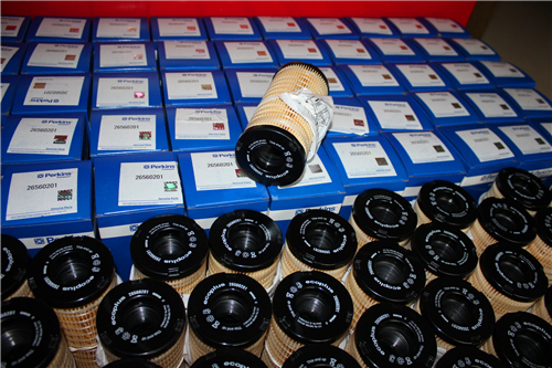
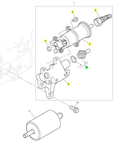
Perkins1204柴油发动机燃油滤清器
详细描述
项目 零配件号码 新件号 描述
19 1 排泄栓塞
20 1 密封O型圈
21 1 密封O型圈
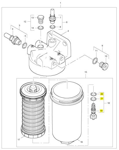
项目 零配件号码 新件号 描述
2 1 燃油过滤器座
3 5 栓塞
4 2 连接器
5 T410737 1 T410737 栓塞
5 T410730 1 T410730 螺旋
8 T417241 1 T417241 感应传感器
8 T410761 1 T417241 感应传感器
9 3636685 1 3636685 燃油过滤器体

项目 零配件号码 新件号 描述
2 1 燃油过滤器座
3 T411282 2 T411282 连接器
6 T417706 1 T417706 连接器
9 T410731 1 T410731 栓塞
12 T410737 1 T410737 栓塞
15 3611272 1 3611272 燃油过滤器组合

项目 零配件号码 新件号 描述
1 T417469 1 T417469 提升泵
1 T408708 1 T408708 提升泵装备
10 2314 H003 3 2314 H003 螺旋
11 T412017 1 T412017 燃油过滤器
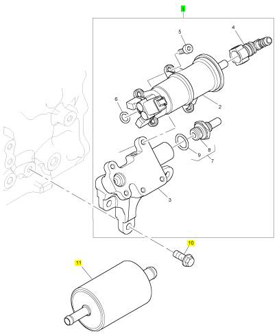
项目 零配件号码 新件号 描述
2 1 提升泵
3 1 托架
4 T408676 1 T408676 连接器
5 T409263 4 T409263 螺拴
6 T411381 1 T411381 密封O型圈
7 T408437 1 T408437 连接
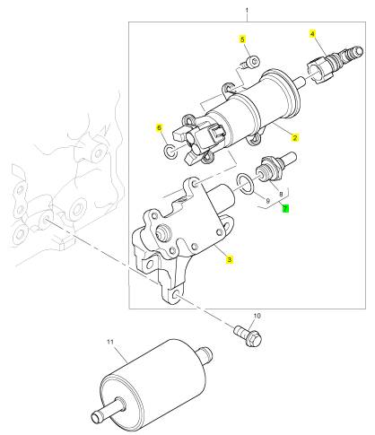
项目 零配件号码 新件号 描述
2 1 提升泵
3 1 托架
4 T408676 1 T408676 连接器
5 T409263 4 T409263 螺拴
6 T411381 1 T411381 密封O型圈
7 T408437 1 T408437 连接
项目 零配件号码 新件号 描述
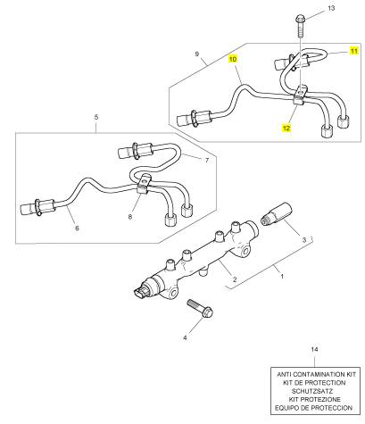
1 T405865 1 T405865 燃油轨条
4 2314 J009 2 2314 J009 螺旋
5 T408573 1 T408573 管 - 高的压力燃油
9 T408571 1 T408571 管 - 高的压力燃油
13 2314 F006 2 2314 F006 螺旋
14 T410437 1 T410437 保护装备

项目 零配件号码 新件号 描述
2 1 燃油轨条
3 T408524 1 T408524 放泄阀

项目 零配件号码 新件号 描述
6 T408551 1 T408551 以管输送 - 燃油 INJ 没有 1 CYL
7 T408550 1 T408550 以管输送 - 燃油 INJ 没有 2 CYL
8 T411397 1 T411397 管夹

项目 零配件号码 新件号 描述
10 T408585 1 T408585 以管输送 - 燃油 INJ 没有 3 CYL
11 T408559 1 T408559 以管输送 - 燃油 INJ 没有 4 CYL
12 T411397 1 T411397 管夹
|
KENR9116-01 |
|
13 Troubleshooting Section |
|
Duty Cycle – Refer to “Pulse Width Modulation”. |
|
Failure Mode Identifier (FMI) – This identifier indicates the type of failure that is associated with the component. The FMI has been adopted from the SAE practice of J1587 diagnostics. The FMI follows the parameter identifier (PID) in the descriptions of the fault code. The descriptions of the FMIs are in the following list. |
|
Electronic Engine Control – The electronic engine control is a complete electronic system. The electronic engine control monitors the engine operation under all conditions. The electronic engine control also controls the engine operation under all conditions. |
|
0 – The data is valid but the data is above the normal |
|
Electronic Control Module (ECM) – The ECM is the control computer of the engine. The ECM provides power to the electronics. The ECM monitors data that is input from the sensors of the engine. The ECM acts as a governor in order to control the speed and the power of the engine. |
|
operational range. |
|
1 – The data is valid but the data is below the normal operational range. |
|
2 – The data is erratic, intermittent, or incorrect. |
|
Electronic Service Tool – The electronic service tool allows a computer (PC) to communicate with the ECM. |
|
3 – The voltage is above normal or the voltage is shorted high. |
|
4 – The voltage is below normal or the voltage is shorted low. |
|
Engine Monitoring – Engine Monitoring is the part of the electronic engine control that monitors the sensors. Engine monitoring also warns the operator of detected problems. |
|
5 – The current is below normal or the circuit is open. |
|
6 – The current is above normal or the circuit is grounded. |
|
Engine Oil Pressure Sensor – The engine oil pressure sensor measures engine oil pressure. The sensor sends a signal to the ECM that is dependent on the engine oil pressure. |
|
7 – The mechanical system is not responding properly. |
|
Engine Speed/Timing Sensor – An engine speed/timing sensor is a hall effect switch that provides a digital signal to the ECM. The ECM interprets this signal as the crankshaft position and the engine speed. Two sensors are used to provide the speed and timing signals to the ECM. The primary sensor is associated with the crankshaft and the secondary sensor is associated with the camshaft. |
|
8 – There is an abnormal frequency, an abnormal pulse width, or an abnormal time period. |
|
9 – There has been an abnormal update. 10 – There is an abnormal rate of change. 11 – The failure mode is not identifiable. 12 – The device or the component is damaged. 13 – The device requires calibration. |
|
Ether Injection – Ether injection is a starting aid in cold conditions. Glow plugs are used as a starting aid when the ambient temperature is between 5° C (41° F) and −25° C (−13° F). At a temperature that is lower than −25° C (−13° F), the glow plugs are disabled and ether injection is used. |
|
14 – There is a special instruction for the device. 15 – The signal from the device is high (least severe). |
|
Event Code – An event code may be activated in order to indicate an abnormal engine operating condition. These codes usually indicate a mechanical problem instead of an electrical system problem. |
|
16 – The signal from the device is high (moderate severity). |
|
17 – The signal from the device is low (least severe). |
|
Exhaust Back Pressure Valve – The exhaust back pressure valve regulates the gas pressure in the exhaust system. The valve can restrict the flow of exhaust gases in order to increase the exhaust back pressure. An increase in exhaust back pressure will increase the temperature of the exhaust gases. The increase in temperature will improve the process that burns off the soot in the CDPF. |
|
18 – The signal from the device is low (moderate severity). |
|
19 – There is an error in the data from the device. |
|
31 – The device has failed and the engine has shut down. |
|
This document is printed from SPI². Not for RESALE |
![]()
|
14 |
|
KENR9116-01 |
|
Troubleshooting Section |
|
Flash File – This file is software that is inside the ECM. The file contains all the instructions (software) for the ECM and the file contains the performance maps for a specific engine. The file may be reprogrammed through flash programming. |
|
Harness – The harness is the bundle of wiring (loom) that connects all components of the electronic system. |
|
Hertz (Hz) – Hertz is the measure of electrical |
|
frequency in cycles per second. |
|
Flash Programming – Flash programming is the method of programming or updating an ECM with an electronic service tool over the data link instead of replacing components. |
|
High Pressure Fuel Pump – This pump is a device that supplies fuel under pressure to the fuel rail (high-pressure fuel rail). |
|
FRC – See “Fuel Ratio Control”. |
|
High Pressure Fuel Rail – See “Fuel Rail”. |
|
Fuel Pump – See “High Pressure Fuel Pump”. |
|
Injector Trim Codes – Injector trim codes are codes that contain 30 characters. The codes are supplied with new injectors. The code is input through the electronic service tool into the ECM. The injector trim codes compensate for variances in manufacturing of the electronic unit injector and for the life of the electronic unit injector. |
|
Fuel Rail – This item is sometimes referred to as the High Pressure Fuel Rail. The fuel rail supplies fuel to the electronic unit injectors. The high-pressure fuel pump and the fuel rail pressure sensor work with the ECM in order to maintain the desired fuel pressure in the fuel rail. This pressure is determined by calibration of the engine in order to enable the engine to meet emissions and performance requirements. |
|
Intake Manifold Air Temperature Sensor – The intake manifold air temperature sensor detects the air temperature in the intake manifold. The ECM monitors the air temperature and other data in the intake manifold in order to adjust injection timing and other performance functions. |
|
Fuel Rail Pressure Sensor – The fuel rail pressure sensor sends a signal to the ECM that is dependent on the pressure of the fuel in the fuel rail. |
|
Fuel Ratio Control (FRC) – The FRC is a limit that is based on the control of the ratio of the fuel to air. The FRC is used for purposes of emission control. When the ECM senses a higher intake manifold air pressure (more air into the cylinder), the FRC increases the FRC Limit (more fuel into the cylinder). |
|
Intake Manifold Pressure Sensor – The Intake Manifold Pressure Sensor measures the pressure in the intake manifold. The pressure in the intake manifold may be different to the pressure outside the engine (atmospheric pressure). The difference in pressure may be caused by an increase in air pressure by a turbocharger. |
|
Full Load Setting (FLS) – The FLS is the parameter that represents the fuel system adjustment. This adjustment is made at the factory in order to fine-tune the fuel system. This parameter must be programmed. |
|
Integrated Electronic Controls – The engine is designed with the electronic controls as a necessary part of the system. The engine will not operate without the electronic controls. |
|
Full Torque Setting (FTS) – The FTS is the parameter that represents the adjustment for the engine torque. This adjustment is made at the factory in order to fine-tune the fuel system. This adjustment is made with the FLS. This parameter must be programmed. |
|
J1939 CAN Data Link – This data link is a SAE standard diagnostic communications data link that is used to communicate between the ECM and other electronic devices. |
|
Logged Diagnostic Codes – Logged diagnostic codes are codes which are stored in the memory. These codes are an indicator of possible causes for intermittent problems. Refer to the term “Diagnostic Trouble Codes” for more information. |
|
Glow Plug – The glow plug is an optional starting aid for cold conditions. One glow plug is installed in each combustion chamber in order to improve the ability of the engine to start. The ECM uses information from the engine sensors to determine when the glow plug relay must provide power to each glow plug. Each of the glow plugs then provides a hot surface in the combustion chamber in order to vaporize the mixture of air and fuel. The vaporization improves ignition during the compression stroke of the cylinder. |
|
NOx Reduction System – The NOx Reduction System recycles a portion of the exhaust gases back into the inlet air. The recirculation reduces the oxides of nitrogen (NOx) in the exhaust gases. The recycled exhaust gas passes through a cooler before being introduced into the inlet air. |
|
Glow Plug Relay – The glow plug relay is controlled by the ECM in order to provide high current to the glow plugs. |
|
OEM – OEM is an abbreviation for the Original Equipment Manufacturer. The OEM is the manufacturer of the machine or the vehicle that uses the engine. |
|
This document is printed from SPI². Not for RESALE |
![]()
|
KENR9116-01 |
|
15 Troubleshooting Section |
|
Open Circuit – An open circuit is a condition that is caused by an open switch, or by an electrical wire or a connection that is broken. When this condition exists, the signal or the supply voltage can no longer reach the intended destination. |
|
Parameter – A parameter is a value or a limit that is programmable. A parameter helps determine specific characteristics or behaviors of the engine. |
|
Password – A password is a group of numeric characters or a group of alphanumeric characters that is designed to restrict access to parameters. The electronic system requires correct passwords in order to change some parameters (Factory Passwords). Refer to Troubleshooting, “Factory Passwords” for more information. |
|
Personality Module – See “Flash File”. |
|
Power Cycling – Power cycling refers to the action of cycling the keyswitch from any position to the OFF position, and to the START/RUN position. |
|
g01858875 |
|
Illustration 7 |
|
Rated Fuel Limit – The rated fuel limit is a limit that is based on the power rating of the engine and on the engine rpm. The Rated Fuel Limit enables the engine power and torque outputs to conform to the power and torque curves of a specific engine model. These limits are in the flash file and these limits cannot be changed. |
|
Pressure Limiting Valve (PLV) – The PLV is a valve in the fuel rail that prevents excessive pressure. The PLV will reduce the pressure to a safe level that will limit engine operation but the reduced pressure will not stop the engine. |
|
Primary Speed/Timing Sensor – This sensor determines the position of the crankshaft during engine operation. If the primary speed/timing sensor fails during engine operation, the secondary speed/timing sensor is used to provide the signal. |
|
Reference Voltage – Reference voltage is a regulated voltage and a steady voltage that is supplied by the ECM to a sensor. The reference voltage is used by the sensor to generate a signal voltage. |
|
Pulse Width Modulation (PWM) – The PWM is a signal that consists of pulses that are of variable width. These pulses occur at fixed intervals. The ratio of “TIME ON” versus “TIME OFF” can be varied. This ratio is also referred to as a duty cycle. |
|
Relay – A relay is an electromechanical switch. A flow of electricity in one circuit is used to control the flow of electricity in another circuit. A small current or voltage is applied to a relay in order to switch a much larger current or voltage. |
|
Secondary Speed/Timing Sensor – This sensor determines the position of the camshaft during engine operation. If the primary speed/timing sensor fails during engine operation, the secondary speed/timing sensor is used to provide the signal. |
|
Sensor – A sensor is a device that is used to detect the current value of pressure or temperature, or mechanical movement. The information that is detected is converted into an electrical signal. |
|
Short Circuit – A short circuit is a condition that has an electrical circuit that is inadvertently connected to an undesirable point. An example of a short circuit is a wire which rubs against a vehicle frame and this rubbing eventually wears off the wire insulation. Electrical contact with the frame is made and results in a short circuit. |
|
This document is printed from SPI². Not for RESALE |
![]()
![]()

|
16 |
|
KENR9116-01 |
|
Troubleshooting Section |
|
Signal – The signal is a voltage or a waveform that is used in order to transmit information typically from a sensor to the ECM. |
|
Wastegate – The wastegate is a device in a turbocharged engine that controls the maximum boost pressure that is provided to the inlet manifold. |
|
Suction Control Valve (SCV) – The SCV is a control device in the high-pressure fuel pump. The valve controls the pressure in the fuel rail by varying the amount of fuel that enters the chambers in the pump. |
|
Wastegate Regulator – The wastegate regulator controls the pressure in the intake manifold to a value that is determined by the ECM. The wastegate regulator provides the interface between the ECM and the mechanical system. The wastegate regulates intake manifold pressure to the desired value that is determined by the software. |
|
Supply Voltage – The supply voltage is a continuous voltage that is supplied to a component. The power may be generated by the ECM or the power may be battery voltage that is supplied by the engine wiring. |
|
i04084033 |
|
Suspect Parameter Number (SPN) – The SPN is a J1939 number that identifies the specific component of the electronic control system that has experienced a diagnostic code. |
|
Electronic Service Tools |
|
Perkins electronic service tools are designed to help the service technician: |
|
System Configuration Parameters – System configuration parameters are parameters that affect emissions and/or operating characteristics of the engine. |
|
• Retrieve diagnostic codes. • Diagnose electrical problems. • Read parameters. |
|
Tattletale – Certain parameters that affect the operation of the engine are stored in the ECM. These parameters can be changed by use of the electronic service tool. The tattletale logs the number of changes that have been made to the parameter. The tattletale is stored in the ECM. |
|
• Program parameters. |
|
• Install injector trim codes. |
|
Throttle Position – The throttle position is the interpretation by the ECM of the signal from the throttle position sensor or the throttle switch. |
|
Required Service Tools |
|
Table 1 |
|
Throttle Position Sensor – The throttle position sensor is a sensor that is normally connected to an accelerator pedal or a hand lever. This sensor sends a signal to the ECM that is used to calculate desired engine speed. |
|
Required Service Tools |
|
Part Number CH11155 |
|
Description Crimp Tool (12−AWG TO 18−AWG) Wire Removal Tool |
|
2900A019 |
|
Throttle Switch – The throttle switch sends a signal to the ECM that is used to calculate desired engine speed. |
|
27610285 |
|
Removal Tool |
|
- |
|
Suitable Digital Multimeter |
|
Top Center Position – The top center position refers to the crankshaft position when the engine piston position is at the highest point of travel. The engine must be turned in the normal direction of rotation in order to reach this point. |
|
Two short jumper wires are needed to check the continuity of some wiring harness circuits by shorting two adjacent terminals together in a connector. A long extension wire may also be needed to check the continuity of some wiring harness circuits. |
|
Total Tattletale – The total tattletale is the total number of changes to all the parameters that are stored in the ECM. |
|
Optional Service Tools |
|
Table 2 lists the optional service tools that can be used when the engine is serviced. |
|
Wait To Start Lamp – This lamp is included in the cold starting aid circuit in order to indicate when the wait to start period is active. The lamp will go off when the engine is ready to be started. The glow plugs may not have deactivated. |
|
This document is printed from SPI². Not for RESALE |
![]()
|
KENR9116-01 |
|
17 Troubleshooting Section |
|
Table 2 |
|
Table 3 |
|
Part Number U5MK1092 |
|
Description |
|
Service Tools for the Use of the Electronic Service Tool |
|
Spoon Probe Kit(MULTIMETER) |
|
Part |
|
Description |
|
- or - |
|
Suitable Digital Pressure Indicator or Engine Pressure Group |
|
Number |
|
-(1) |
|
Single Use Program License |
|
- - |
|
- (1) |
|
Suitable Battery Load Tester |
|
Data Subscription for All Engines |
|
Suitable Temperature Adapter (MULTIMETER) |
|
Communication Adapter (Electronic Service Tool to the ECM interface) |
|
27610251 27610164 |
|
28170107 2900A038 |
|
Bypass Harness As Harness as |
|
Adapter Cable As |
|
(1) Refer to Perkins Engine Company Limited. |
|
Note: For more information on the Electronic Service Tool and the PC requirements, refer to the documentation that accompanies the software for the Electronic Service Tool. |
|
Perkins Electronic Service Tool |
|
The Perkins Electronic Service Tool can display the following information: |
|
Connecting the Electronic Service Tool and the Communication Adapter II |
|
• Status of all pressure sensors and temperature sensors |
|
• Programmable parameter settings |
|
• Active diagnostic codes and logged diagnostic codes |
|
• Logged events • Histograms |
|
The Electronic Service Tool can also be used to perform the following functions: |
|
• Diagnostic tests |
|
• Sensor calibrations |
|
• Programming of flash files and injector trim codes • Parameter programming • Copy configuration function for ECM replacement • Data logging |
|
• Graphs (real time) |
|
Table 3 lists the service tools that are required in order to use the Electronic Service Tool. |
|
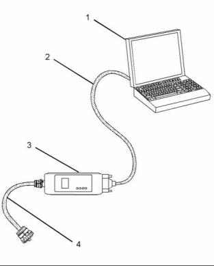
g01121866 |
|
Illustration 8 |
|
(1) Personal Computer (PC) |
|
(2) Adapter Cable (Computer Serial Port) (3) Communication Adapter II (4) Adapter Cable Assembly |
|
Note: Items (2), (3) and (4) are part of the Communication Adapter II kit. |
|
Use the following procedure in order to connect the Electronic Service Tool and the Communication Adapter II. |
|
This document is printed from SPI². Not for RESALE |
![]()

![]()
|
18 |
|
KENR9116-01 |
|
Troubleshooting Section |
|
1. Turn the keyswitch to the OFF position. |
|
Warning Lamp |
|
2. Connect cable (2) between the “COMPUTER” end of communication adapter (3) and the RS232 serial port of PC (1). |
|
Lamp check – When the keyswitch is turned to ON, the lamp will come on for 2 seconds. The lamp will then go off unless there is an active warning. |
|
Note: The Adapter Cable Assembly (4) is required to connect to the USB port on computers that are not equipped with an RS232 serial port. |
|
Flashing – The lamp will be flashing when a “warning” or a “warning and derate” is active. This includes low oil pressure. |
|
3. Connect cable (4) between the “DATA LINK” end of communication adapter (3) and the service tool connector. |
|
On – The lamp will be on when the shutdown level has been reached. The “Shutdown” lamp will also be on. |
|
4. Place the keyswitch in the ON position. If the Electronic Service Tool and the communication adapter do not communicate with the Electronic Control Module (ECM), refer to the diagnostic procedure Troubleshooting, “Electronic Service Tool DoesNot Communicate”. |
|
Wait to Start Lamp |
|
Lamp check – When the keyswitch is turned to ON, the lamp will come on for 2 seconds. The lamp will then go off unless “Wait to Start” is active. |
|
On – The lamp is on during a “Wait to Start” period. |
|
i03834091 |
|
Low Oil Pressure |
|
Indicator Lamps |
|
Lamp check – When the keyswitch is turned to ON, the lamp will come on for 2 seconds. The lamp will then go off unless there is an active warning. |
|
Indicator Lamps |
|
On – The lamp will come on when a low oil pressure event is detected. The “Warning” lamp and the “Shutdown” lamp may also come on. |
|
Four lamps are available as options. The “Shutdown” lamp and the “Warning” lamp will normally be installed in the application. Dedicated optional lamps for other items may also be installed. The remaining optional lamps are “Wait to start” and “Low oil pressure”. |
|
Note: On a cold start, when the Electronic Control Module (ECM) determines that it is necessary for the glow plugs to be activated prior to starting, a lamp output will indicate that the operator needs to “Wait to Start”. It is possible that starting aids may be used during the cranking of the engine. Starting aids may be used if the engine has previously been started. The “Wait to Start” lamp will not be active in these conditions. |
|
The “Shutdown” lamp and the “Warning” lamp can also be used to indicate a diagnostic code by use of the “Flash Code” feature. The “Flash Code” feature can be used to indicate all active diagnostic codes and logged diagnostic codes. |
|
Functions of the Lamps |
|
Color of Lamps |
|
Shutdown Lamp |
|
Typically, the “Shutdown” lamp is colored red and the “Warning” lamp is colored amber. The other lamps are optional. |
|
Lamp check – When the keyswitch is turned to ON, the lamp will come on for 2 seconds. The lamp will then go off unless there is an active warning. |
|
Flashing – The lamp will be flashing when a derate is active or when a derate is present because of an active diagnostic code. An example of an active diagnostic code is “System Voltage High”. |
|
On – The lamp will be on when the shutdown level in the engine protection strategy has been reached. The “Warning” lamp will also be on. |
|
This document is printed from SPI². Not for RESALE |
![]()
|
KENR9116-01 |
|
19 Troubleshooting Section |
|
Operation of the Indicator Lamps |
|
Table 4 |
|
Warning Lamp (Alert |
|
Shutdown Lamp (Action |
|
Lamp State Lamp Check No Faults |
|
Description of the Indication |
|
Engine State |
|
Lamp) |
|
Lamp) |
|
On |
|
On |
|
When the keyswitch is moved to the ON position, the lamps come on for a period of 2 seconds and the lamps will then go off. |
|
The keyswitch is in the ON position but the engine has not yet been cranked. |
|
Off On |
|
Off Off |
|
With the engine in operation, there are no active warnings, diagnostic codes or event codes. |
|
The engine is operating with no detected faults. |
|
Active Diagnostic |
|
If the warning lamp comes on during engine operation, this indicates that an active diagnostic code (an electrical fault) is present. |
|
The engine is operating normally but there is one or more faults with the electronic management system for the engine. |
|
On |
|
Flashing |
|
Derate (A derate is caused by certain active codes.) |
|
If the warning lamp comes on and the The engine is operating but there is one shutdown lamp flashes during engine or more active diagnostic codes that operation, this indicates that an active have initiated an engine derate. diagnostic code (an electrical fault) is |
|
present. The diagnostic is sufficiently |
|
serious in order to cause an engine derate. |
|
Flashing |
|
Off |
|
Warning (Warning only) during operation of the engine, the lamp indicates that one or |
|
When the warning lamp flashes |
|
The engine is operating normally. However, there is one or more of the monitored engine parameters that are outside of the range that is acceptable. |
|
more of the warning values for the engine protection strategy has been exceeded. However, the value has not been exceeded to a level that will cause a derate or a shutdown. |
|
Flashing Flashing |
|
Off |
|
Warning (Warning only) Diesel Particulate Filter (DPF). |
|
There is a high soot loading in the |
|
The soot loading in the DPF has reached 100%. The engine will be derated. The lamp warns the operator that the engine needs to be operated in a mode that promotes regeneration. |
|
Flashing |
|
Derate (Warning and Derate) |
|
If both the warning lamp and shutdown lamp flash during operation one or more of the monitored engine of the engine, the lamps indicate that parameters is outside of the acceptable |
|
The engine is operating. However, |
|
one or more of the values for the |
|
range. The acceptable range has been |
|
engine protection strategy have been exceeded to a level which requires a |
|
exceeded beyond the level that will cause an engine derate. |
|
warning and an engine derate. |
|
Flashing On |
|
On On |
|
Very high DPF The soot loading in the DPF is high. soot loading |
|
The soot loading in the DPF has reached 120%. The engine must be operated in a mode that promotes regeneration. |
|
Engine Shutdown |
|
If both the warning lamp and the shutdown lamp come on during engine operation, this indicates one of the following conditions. |
|
The engine is either shutdown or an engine shutdown is imminent. One or more monitored engine parameters have exceeded the limit for an engine shutdown. This pattern of lamps can be caused by the detection of a serious active diagnostic code. |
|
1. One or more of the shutdown values for the engine protection strategy has been exceeded. |
|
2. A serious active diagnostic code has been detected. |
|
After a short period of time, the engine will shut down. |
|
This document is printed from SPI². Not for RESALE |
![]()

|
20 |
|
KENR9116-01 |
|
Troubleshooting Section |
|
Flash Codes |
|
The “Flash Code” feature is used to flash the code of all active diagnostic codes and logged diagnostic codes. |
|
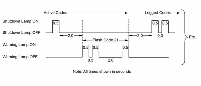
The sequence for the flash code is started by moving the keyswitch to “Off” and then moving the keyswitch to “On” twice within a period of three seconds. After a delay of 2 seconds, the “Shutdown” lamp will flash once for a period of half a second. This sequence indicates the start of the active fault codes. After a further delay of 2 seconds, the “Warning” lamp will flash repeatedly in order to indicate the active diagnostic codes. Each flash will be on for half a second and off for 300 milliseconds. The “Warning” lamp will remain off for 2 seconds between each digit of a code. If there is more than one active diagnostic code, the “Shutdown” lamp will go off for 2 seconds. The lamp will then come on for a period of half a second. The “Warning” lamp will go off for a period of 2 seconds before starting the next code. If there are no active diagnostic codes, the “Warning” lamp will flash the code “551”. Refer to Troubleshooting Guide, “No Diagnostic Code Detected”. |
|
As an example, an active diagnostic code of “21” is indicated by the “Warning” lamp coming on for 500 ms, then off for 300 ms, then on for 500 ms, then off for 2000 ms, then on for 500 ms and then off. |
|
g01779334 |
|
Illustration 9 |
|
Timing of the flash codes |
|
After all of the active diagnostic codes have been displayed, the “Shutdown” lamp will go off for 2 seconds. The “Shutdown” lamp will flash twice in order to indicate the start of the sequence that will display the logged diagnostic codes. The process for flashing logged diagnostic codes is identical to the process for flashing active diagnostic codes. |
|
Note: If there are no logged codes then the “551” code should be flashed again. |
|
This document is printed from SPI². Not for RESALE |
![]()
![]()
|
KENR9116-01 |
|
21 Troubleshooting Section |
|
After all of the codes have been displayed, the “Shutdown” lamp will flash 3 times in order to indicate that there are no further codes. Cycling the keyswitch twice within a period of 3 seconds will start the process again. All codes will be displayed in ascending numerical order. |
|
Note: If an ECM is to be used as a test ECM, “Test ECM Mode” must be selected on the electronic service tool before the engine serial number is entered. |
|
Use the electronic service tool to read the parameters in the suspect ECM. Record the parameters in the suspect ECM. Install the flash file into the new ECM. After the ECM is installed on the engine, the parameters must be programmed into the new ECM. |
|
Refer to the Troubleshooting Guide, “Diagnostic Code Cross Reference” for the diagnostic code that relates to the flash code. |
|
Note: Flash codes are always sent in ascending numerical order. |
|
Note: When a new ECM is not available, an ECM can be used from an engine that is not in service. The ECM must have the same serial number suffix. Ensure that the replacement ECM and the part number for the flash file match the suspect ECM. Be sure to record the parameters from the replacement ECM. Use the “Copy Configuration ECM Replacement” function in the electronic service tool. |
|
i04319696 |
|
Replacing the ECM |
|
NOTICE If the flash file and engine application are not matched, engine damage may result. |
|
NOTICE |
|
Care must be taken to ensure that fluids are contained during performance of inspection, maintenance, test- ing, adjusting, and repair of the product. Be prepared to collect the fluid with suitable containers before opening any compartment or disassembling any com- ponent containing fluids. |
|
Perform the following procedure in order to replace the ECM. |
|
1. Connect the electronic service tool to the diagnostic connector. |
|
Dispose of all fluids according to local regulations and mandates. |
|
2. Use the “Copy Configuration ECM Replacement” function from the electronic service tool. If the process is successful, proceed to Step 4. If the “Copy Configuration” failed, proceed to Step 3. |
|
NOTICE Keep all parts clean from contaminants. |
|
Contaminants may cause rapid wear and shortened component life. |
|
Note: Record any Logged Faults and Events for your records. |
|
The engine is equipped with an Electronic Control Module (ECM). The ECM contains no moving parts. Follow the troubleshooting procedures in this manual in order to be sure that replacing the ECM will correct the fault. Verify that the suspect ECM is the cause of the fault. |
|
3. Record the following parameters: |
|
• • • |
|
Record all of the parameters on the |
|
“Configuration” screen. |
|
Record all of the parameters on the “Throttle |
|
Configuration” screen. |
|
Note: Ensure that the ECM is receiving power and that the ECM is properly grounded before replacement of the ECM is attempted. Refer to the schematic diagram. |
|
Record all of the parameters on the “Mode |
|
Configuration” screen. |
|
• Record the serial numbers of the electronic unit injectors. The injector serial numbers are shown on the “Injector Trim Calibration” screen. |
|
A test ECM can be used in order to determine if the ECM on the engine is faulty. Install a test ECM in place of the suspect ECM. Install the flash file with the correct part number into the test ECM. Program the parameters for the test ECM. The parameters must match the parameters in the suspect ECM. Refer to the following test steps for details. If the test ECM resolves the fault, reconnect the suspect ECM. Verify that the fault returns. If the fault returns, replace the ECM. |
|
Note: If the parameters cannot be read, the parameters must be obtained elsewhere. Some parameters are stamped on the engine information plate, but most parameters must be obtained from the PTMI data on the Perkins web site. |
|
4. Remove power from the ECM. |
|
This document is printed from SPI². Not for RESALE |
![]()
![]()
![]()
![]()
![]()
![]()
![]()
|
22 |
|
KENR9116-01 |
|
Troubleshooting Section |
|
5. Remove the ECM. Refer to Disassembly and Assembly, “Electronic Control Module - Remove and Install”. |
|
Diagnostic Trouble Code – When a fault in the electronic system is detected, the ECM generates a diagnostic trouble code. The diagnostic trouble code indicates the specific fault in the circuitry. |
|
6. Install the replacement ECM. Refer to Disassembly and Assembly, “Electronic Control Module - Remove and Install”. |
|
Diagnostic codes can have two different states: |
|
• Active |
|
7. If the replacement ECM is to be used as a test ECM, select “Test ECM Mode” on the electronic service tool. |
|
• Logged |
|
Active Code – An active diagnostic code indicates that an active fault has been detected by the control system. Active codes require immediate attention. Always service active codes prior to servicing logged codes. |
|
8. Download the flash file. |
|
a. Connect the electronic service tool to the diagnostic connector. |
|
b. Select “WinFlash” from the “Utilities” menu of the electronic service tool. |
|
Logged Code – Every generated code is stored in the permanent memory of the ECM. The codes are logged for 100 operating hours unless a code is cleared by use of the electronic service tool. |
|
c. Select the downloaded flash file. |
|
9. If necessary, use the electronic service tool to clear the rating interlock. To clear the rating interlock, enter the factory password when the electronic service tool is first connected. Activating the Test ECM mode will also clear the rating interlock. |
|
Logged codes may not indicate that a repair is needed. The fault may have been temporary. The fault may have been resolved since the logging of the code. If the system is powered, an active diagnostic trouble code may be generated whenever a component is disconnected. When the component is reconnected, the code is no longer active. Logged codes may be useful to help troubleshoot intermittent faults. Logged codes can also be used to review the performance of the engine and the electronic system. |
|
10. Use the electronic service tool to program the parameters. Perform the following procedure. |
|
a. If the “Copy Configuration” procedure was successful, use the “Copy Configuration, ECM Replacement” function to load the configuration file into the ECM. |
|
i04215569 Sensors and Electrical Connectors |
|
Note: During the following procedure, factory passwords may be required. |
|
b. If the “Copy Configuration” procedure failed, configure the parameters individually. The parameters should match the parameters from step 3. |
|
The Electronic Control Module (ECM) and most of the engine sensors are located on the left side of the engine. For the 1204E-E44 engine, refer to Illustration 10. For the remaining sensors that are attached to the 1204E-E44 engine, refer to Illustration 12. For the 1206E-E66 engine, refer to Illustration 14 . For the remaining sensors that are attached to the 1206E-E66 engine, refer to Illustration 16. For the sensors and components on the Clean Emissions Module (CEM), refer to Illustration 18. |
|
Perform the “Fuel System Verification Test”. |
|
11. Check for logged diagnostic codes. Factory passwords are required to clear logged events. |
|
i03951470 |
|
Self-Diagnostics |
|
Note: In the following illustrations, some components |
|
have been removed in order to improve visibility. |
|
The Electronic Control Module (ECM) can detect faults in the electronic system and with engine operation. A self-diagnostic check is also performed whenever power is applied to the ECM. |
|
When a fault is detected, a diagnostic trouble code is generated. This code conforms to the SAE J1939 standard. An alarm may also be generated. |
|
This document is printed from SPI². Not for RESALE |
![]()
|
KENR9116-01 |
|
23 Troubleshooting Section |
|
Typical 1204E-E44 Engine |
|
g02479176 |
|
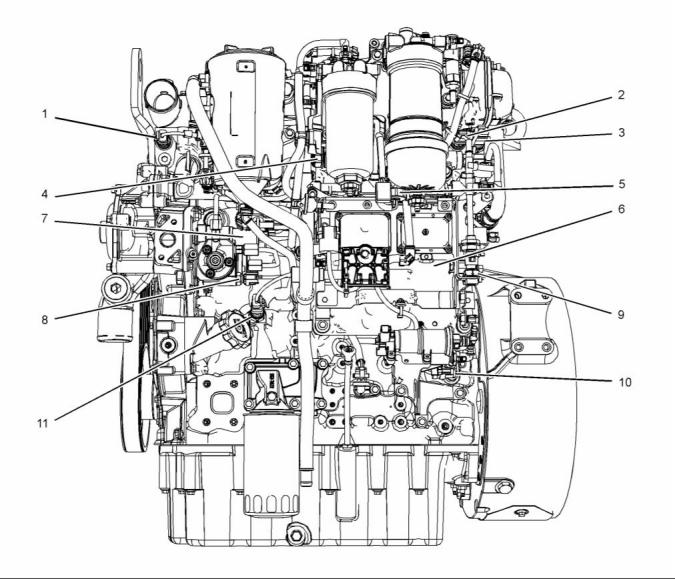
Illustration 10 |
|
Sensor locations on the left side of a typical 1204E-E44 engine |
|
(1) Coolant temperature sensor (2) Intake manifold air temperature sensor (3) Intake manifold pressure sensor (4) Fuel rail pressure sensor |
|
(5) Water-in-fuel switch |
|
(8) Fuel temperature sensor |
|
(6) Electronic Control Module (ECM) (7) Suction control valve for the high-pressure fuel pump |
|
(9) Barometric pressure sensor (10) Primary speed/timing sensor (11) Oil pressure sensor |
|
This document is printed from SPI². Not for RESALE |
![]()
![]()
|
24 |
|
KENR9116-01 |
|
Troubleshooting Section |
|
g02479258 |
|
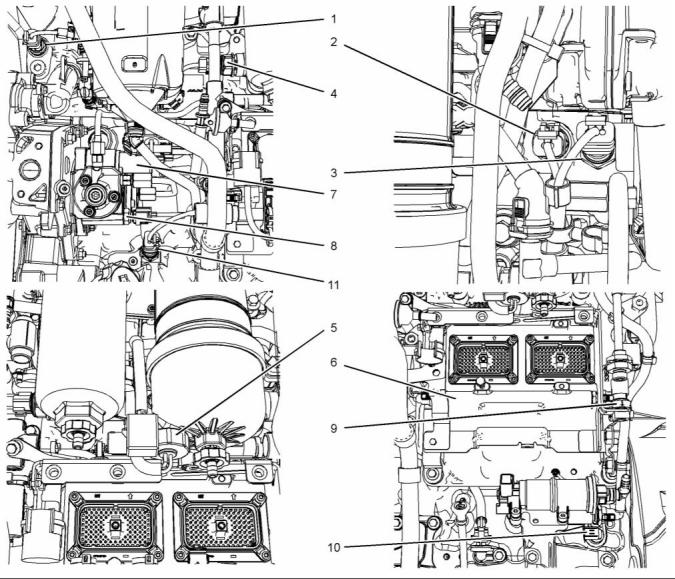
Illustration 11 |
|
Close up views of sensor locations on the left side of a typical 1204E-E44 engine |
|
(1) Coolant temperature sensor (2) Intake manifold air temperature sensor (3) Intake manifold pressure sensor (4) Fuel rail pressure sensor |
|
(5) Water-in-fuel switch |
|
(8) Fuel temperature sensor |
|
(6) Electronic Control Module (ECM) (7) Suction control valve for the high-pressure fuel pump |
|
(9) Barometric pressure sensor (10) Primary speed/timing sensor (11) Oil pressure sensor |
|
This document is printed from SPI². Not for RESALE |
![]()
![]()
|
KENR9116-01 |
|
25 Troubleshooting Section |
|
g02481176 |
|
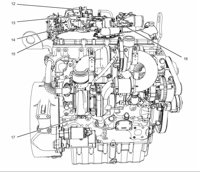
Illustration 12 |
|
Sensor locations on the right side and the top of a typical 1204E-E44 engine |
|
(12) NRS outlet pressure sensor (13) NRS inlet pressure sensor (14) NRS valve |
|
(15) Nox Reduction System (NRS) temperature sensor (16) Wastegate regulator |
|
(17) Secondary speed/timing sensor (18) Exhaust back pressure valve (not illustrated) |
|
This document is printed from SPI². Not for RESALE |
![]()
![]()
|
26 |
|
KENR9116-01 |
|
Troubleshooting Section |
|
g02481197 |
|
Illustration 13 |
|
Close up views of sensor locations on the top of a typical 1204E-E44 engine |
|
(12) NRS outlet pressure sensor (13) NRS inlet pressure sensor (14) NRS valve |
|
(15) Nox Reduction System (NRS) temperature sensor (not illustrated) (16) Wastegate regulator |
|
(17) Secondary speed/timing sensor (not illustrated) (18) Exhaust back pressure valve |
|
This document is printed from SPI². Not for RESALE |
![]()
![]()
|
KENR9116-01 |
|
27 Troubleshooting Section |
|
1206E-E66 Engine |
|
g02481236 |
|
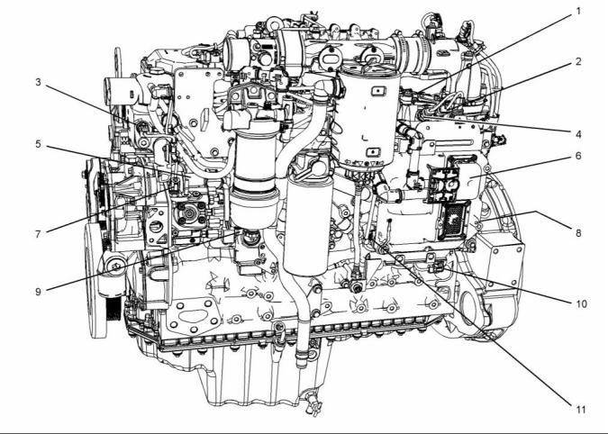
Illustration 14 |
|
Sensor locations on the left side of a typical 1206E-E66 engine |
|
(1) Fuel rail pressure sensor |
|
(5) Suction control valve for the high-pressure fuel pump (6) Electronic Control Module (ECM) (7) Fuel temperature sensor |
|
(8) Barometric pressure sensor (not shown) (9) Water-in-fuel switch (10) Primary speed/timing sensor (11) Oil pressure sensor |
|
(2) Intake manifold pressure sensor (3) Coolant temperature sensor (4) Intake manifold air temperature sensor |
|
This document is printed from SPI². Not for RESALE |
![]()
![]()
|
28 |
|
KENR9116-01 |
|
Troubleshooting Section |
|
g02481796 |
|
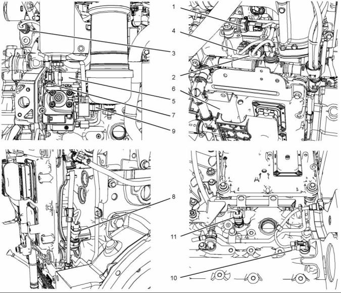
Illustration 15 |
|
Close up views of sensor locations on the left side of a typical 1206E-E66 engine |
|
(1) Fuel rail pressure sensor |
|
(5) Suction control valve for the high-pressure fuel pump (6) Electronic Control Module (ECM) (7) Fuel temperature sensor |
|
(8) Barometric pressure sensor (9) Water-in-fuel switch (10) Primary speed/timing sensor (11) Oil pressure sensor |
|
(2) Intake manifold pressure sensor (3) Coolant temperature sensor (4) Intake manifold air temperature sensor |
|
This document is printed from SPI². Not for RESALE |
![]()
![]()
|
KENR9116-01 |
|
29 Troubleshooting Section |
|
g02483578 |
|
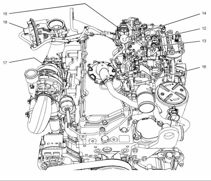
Illustration 16 |
|
Sensor locations on the right side and the top of a typical 1206E-E66 engine |
|
(12) NRS outlet pressure sensor (13) Wastegate regulator (14) NRS valve |
|
(15) NRS inlet pressure sensor (16) Inlet temperature sensor for the NOx Reduction System (NRS) |
|
(17) Secondary speed/timing sensor (18) Exhaust back pressure valve |
|
This document is printed from SPI². Not for RESALE |