Perkins2306柴油发动机威尔逊P550柴油发电机配件供应商,Perkins2306柴油发动机威尔逊P550柴油发电机配件技术价格规格咨询服务,Perkins2306柴油发动机威尔逊P550柴油发电机配件零配件供应,Perkins2306柴油发动机威尔逊P550柴油发电机配件售后服务中心,Perkins2306柴油发动机威尔逊P550柴油发电机配件,Perkins2306柴油发动机威尔逊P550柴油发电机配件详细的技术参数,

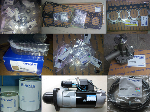
Perkins2306柴油发动机威尔逊P550柴油发电机配件
详细描述
项目 零配件号码 新件号 描述
1 CH11453 1 CH11512 CYL 盖 ASSY
2 CH11353 1 CH11353 密封垫 - 摇臂室盖
3 CH10955 14 CH10955

项目 零配件号码 新件号 描述
1 CH11178 1 检查历史 缸体组合

项目 零配件号码 新件号 描述
1 CH10662 1 CH10662 间隔器
2 1 密封垫
3 1 密封垫
4 CH10661 1 CH10661 合钉
5 CH10656 1 CH10656 合钉
6 CH10659 1 CH10659 合钉
7 CH10660 1 CH10660 密封O型圈
8 CH10221 5 CH10221 栓塞
9 CH10568 2 CH11963 栓塞
10 CH10664 1 CH10664 栓塞
11 CH10667 1 CH10667 密封O型圈
12 CH10658 2 CH10658 合钉
13 CH10663 1 CH10663 栓塞
14 CH10666 2 CH10666 栓塞
15 CH10657 2 CH10657 密封O型圈

Troubleshoot ing
Event Code
with
an
Event Codes
i02564763
Event codes alert the operator that an abnormal
engine operating condition such as low oil pressure or
high coolant temperature has been detected. When
the event code is generated, the event is active.
Active Event Codes
An active event code represents a fault with engine
operation. Correct the fault as soon as possible.
Active event codes are listed in ascending numerical
order. The code with the lowest number is listed first.
Illustration 11 is an example of the operating range of
a temperature sensor. Do not use the illustration to
troubleshoot temperature sensors.
Illustration 11
g01138880
Example of the typical operating range of a temperature sensor
(1) This area represents the normal operating range of the
parameter. The normal output voltage of the sensor is between
0.2 VDC and 4.2 VDC.
(2) In this area, the temperature above 107 °C (225 °F) is higher
than normal. The output voltage of the sensor will generate an
event code. The sensor does not have an electronic fault.
(3) In these areas, the output voltage of the sensor is too high
or too low. The voltage is outside of the normal range. The
elec tronic fault will generate a diagnostic code. Refer to
Troubleshooting, “Troubleshooting with a Diagnostic Code” for
additional information on diagnostic codes.
Events are represented in two formats. In the first
format, the “E” means that the code is an event
code. The “XXX” represents a numeric identifier for
the event code. This is followed by a description of
the code. If a warning, a derate, or a shutdown is
applicable, the numeric identifiers are different. Refer
to the following example:
• E004 Engine Overs peed Shutdown
In the second format, the “E” means that the
code is an event code. The “XXX-X” represents a
numeric identifier for the event code. The fourth “X”
identifies the event as a warning, an ac tion alert, or
a shutdown. This is followed by a description of the
code. Refer to the following example:
This document has been printed from SPI². Not for Resale
![]() 68
68
Troubleshooting Section
KENR6224
•
•
•
E360-1 Low Oil Pressure Warning
E360-2 Low Oil Pressure Action Alert
E360-3 Low Oil Pressure Shutdown
Troubleshooting
For basic troubleshooting of the engine, perform the
following steps in order to diagnose a fault:
1. Obtain the following information about the fault:
The definition for a warning, an action alert and a
shutdown are defined below:
Warning – This condition represents a serious fault
with engine operation. However, this c ondition does
not require an action alert or a s hutdown.
Action Alert – For this condition, the OEM control
panel may shut down the engine.
Shutdown – For this condition, the ECM should shut
down the engine.
Logged Event Codes
•
•
•
•
The event and the time of the event
Determine the conditions for the event. The
conditions will include the engine rpm and the
load.
Determine if there are any systems that were
installed by the dealer or by the customer that
could cause the event.
Determine whether any additional events
occurred.
When the ECM generates an event code, the ECM
logs the code in permanent memory. The ECM has
an internal diagnostic clock. The ECM will record
the following information when an event code is
generated:
• The hour of the first occurrence of the code
• The hour of the last occurrence of the code
• The number of occurrences of the code
Logged events are listed in chronological order. The
most recent event code is listed first.
This information can be helpful for troubleshooting
intermittent faults. Logged codes can als o be used to
review the performance of the engine.
Clearing Event Codes
2.
3.
4.
Verify that the fault is not due to normal engine
operation. Verify that the fault is not due to error of
the operator.
Narrow the probable cause. Consider the operator
information, the conditions of operation, and the
his tory of the engine.
Perform a visual inspection. Inspect the following
items:
• Fuel supply
• Oil level
• Oil supply
• Wiring
• Connectors
A code is cleared from memory when one of the
following conditions occur:
• The code does not recur for 100 hours.
• A new code is logged and there are already ten
codes in memory. In this case, the oldest code is
cleared.
• The service technician manually clears the code.
Always clear logged event codes after investigating
and correcting the fault which generated the code.
Be sure to check the connectors. This is very
important for faults that are intermittent. Refer to
Troubleshooting, “Electrical Connectors - Inspect”.
If these steps do not resolve the fault, identify the
procedures in this manual that best describe the
event. Check each probable cause according to the
tests that are recommended.
Trip Points for the Monitoring
System
The monitoring system determines the level of action
that is taken by the ECM in response to a condition
that can damage the engine. When any of these
conditions occur, the appropriate event code will trip.
This document has been printed from SPI². Not for Resale

![]() KENR6224
KENR6224
69
Troubleshooting Section
Table 11 contains the conditions that are monitored
and the default trip points for each condition.
Each condition has an associated parameter. The
settings for each parameter can be viewed with the
electronic service tool. The trip points for some of
the parameters may be adjustable with the electronic
service tool.
Table 11
Event Code
E162
-1
Parameter
High Boost Pressure
Warn Operator (1)
On
State
Trip Point
300 kPa (43.5 psi)
Delay Time
30 seconds
-2
E360
-1
-2
-3
E361
-1
-2
-3
E362
-1
-2
-3
E363
-1
-2
Acti on Alert (2)
Low Engine Oil Pressure
Warn Operator (1)
Acti on Alert (2)
Engine Shutdown (3)
High Engine Coolant Temperature
Warn Operator (1)
Acti on Alert (2)
Engine Shutdown (3)
Engine Overspeed
Warn Operator (1)
Acti on Alert (2)
Engine Shutdown (3)
High Fuel Supply Temperature
Warn Operator (1)
Acti on Alert (2)
Always On
On
Always On
Always On
On
Always On
Always On
On
Always On
Always On
On
Always On
None
300 kPa (43.5 psi)
None
None
104 °C (2190 °F)
105 °C (221 °F)
108 °C (226 °F)
2000 RPM
2050 RPM
2140 RPM
60 °C (140 °F)
68 °C (154 °F)
5 seconds
60 seconds
2 seconds
2 seconds
60 seconds
10 seconds
10 seconds
1 second
1 second
0 second
60 seconds
60 seconds
E368
-1
-2
High Engine Intake Manifold Air Temperature
Warn Operator (1) On
Acti on Alert (2) Always On
75 °C (167 °F)
78 °C (172 °F)
60 seconds
10 seconds
E162 High
Boost Pressure
i02564844
Possible Performance Effect:
E162-1 (Warning)
None
Conditions Which Generate This Code:
The Electronic Control Module (ECM) detects one of
the following conditions:
• Engine overload
System Response:
The event code will be logged.
E162-2 (Action Alert)
The engine may be shut down by the OEM control
panel.
Troubleshooting:
The engine may be overloaded.
Reduce the load on the engine.
This document has been printed from SPI². Not for Resale
![]() 70
70
Troubleshooting Section
KENR6224
Results:
• OK – STOP.
E360 Low Engine
i02564766
Oil Pressure
b. Oil pump gears that have too much wear will
cause a reduction in oil pressure. Repair the
engine oil pump.
C. The inlet screen of the oil suction tube for the
engine oil pump can have a restriction. This
restriction will cause cavitation and a loss of
engine oil pres sure. Check the inlet screen on
the oil pickup tube and remove any material that
may be restricting engine oil flow. Low engine oil
pressure may also be the result of the oil pickup
Conditions Which Generate This Code:
The Electronic Control Module (ECM) detects a fault
with the engine oil pressure. Information on default
settings and ranges for this event can be found in
Troubleshooting, “Event Codes”.
System Response:
The event code will be logged.
Possible Performance Effect:
E360-1 (Warning)
None
E360-2 (Action Alert)
The engine may be shut down by the OEM control
panel.
E360-3 (Shutdown)
The engine will shut down.
Troubleshooting:
There may be a fault in the lubrication system for
the engine.
Check the Engine’s Lubrication System
A. Check the engine oil level. If the oil lev el is below
the s upply tube for the oil pump, the oil pump will
not have the ability to supply enough lubrication to
the engine components. If the engine oil level is
low, add engine oil in order to obtain the correct
engine oil level.
B. Check the following faults that may occur to the
engine oil pump:
a. Air leakage in the supply side of the oil pump
will also cause cavitation and loss of oil
pressure. Check the supply side of the oil pump
and make necessary repairs.
tube that is drawing in air. Check the joints of the
oil pickup tube for cracks or a damaged O-ring
seal.
D. If the engine oil bypass valves are held in the
open position, a reduction in the oil pressure can
be the result. This may be due to debris in the
engine oil. If the engine oil bypass valves are
stuck in the open position, remove each engine
oil bypass valve and clean each bypass valve in
order to correct this fault. You must also clean
each bypass valve bore.
E. Engine oil that is c ontaminated with fuel or coolant
will cause low engine oil pressure. High engine
oil level in the crankcase can be an indication of
contamination.
F. Excessive clearance at engine bearings will
cause low engine oil pres sure. Check the engine
components for excessive bearing clearance.
G. An oil line that is open, broken, or disconnected
will cause low engine oil pressure.
Expected Result:
An inspection of the lubrication system for the engine
indicated a fault.
Results:
• OK – There is a fault in the lubrication system for
the engine.
Repair: Repair the fault. Ensure that the repair
eliminates the fault.
STOP.
This document has been printed from SPI². Not for Resale
![]() KENR6224
KENR6224
71
Troubleshooting Section
E361
High
Engine
i02564767
Coolant
D. Check the water temperature regulator. A water
temperature regulator that does not open, or a
water temperature regulator that only opens part
of the way can cause overheating.
Temperature
Conditions Which Generate This Code:
The Electronic Control Module (ECM) detects a fault
in the engine cooling sy stem. Information on default
settings and ranges for this event can be found in
Troubleshooting, “Event Codes”.
System Response:
The event code will be logged.
Possible Performance Effect:
E361-1 (Warning)
• There are no performance effects.
E361-2 (Action Alert)
• The engine may be shut down by the OEM control
panel.
E361-3 (Shutdown)
• The engine will be shut down.
Troubleshooting:
There may be a fault in the engine cooling system.
Check the Engine’s Cooling System
A. Verify that the cooling sy stem is filled to the proper
lev el. If the coolant level is too low, air will get into
the cooling system. Air in the cooling system will
cause a reduction in coolant flow.
B. Check the radiator or the heat exchanger for a
restriction to coolant flow.
a. Check for debris or damage between the fins
of the radiator core. Debris between the fins of
the radiator core restricts air flow through the
radiator core.
b. Check internally for debris, dirt, or deposits on
the radiator core. Debris, dirt, or deposits will
restrict the flow of coolant through the radiator.
C. Check the concentration of the Extended Life
Coolant (ELC). Make sure that the coolant
mixture meets recommendations. Refer to the
Operation and Maintenance Manual, “Fluid
Recommendations”.
E. Check the water pump. A water pump with a
damaged impeller does not pump enough coolant.
Remove the water pump and check for damage
to the impeller.
F. If the cooling system for this application is
equipped with a fan, check the operation of the
fan. A fan that is not turning at the correct speed
can cause improper air speed across the radiator
core. The lack of proper air flow across the
radiator c ore can cause the coolant not to cool to
the proper temperature differential.
G. Check for air in the cooling system. Air can enter
the cooling s ystem in different ways. The most
common causes of air in the cooling system are
the incorrect filling of the cooling system and
combustion gas leakage into the cooling system.
Combustion gas can get into the system through
inside cracks, a damaged cylinder head, or a
damaged cylinder head gasket.
H. Check the cooling system hoses and clamps.
Damaged hoses with leaks can normally be seen.
Hoses that have no visual leaks can soften during
operation. The soft areas of the hose can become
kink ed or crushed during operation. These areas
of the hose can restrict the coolant flow. Hoses
become soft and/or get cracks after a period of
time. The inside of a hose can deteriorate, and the
loose particles of the hos e can restrict the coolant
flow.
I. If the cooling system for this application is
equipped with an expansion tank, check the s hunt
line for the expansion tank. The shunt line must be
submerged in the expansion tank. A res triction of
the shunt line from the expansion tank to the inlet
of the jacket water pump will c ause a reduction in
water pump efficiency. A reduction in water pump
efficiency will result in low coolant flow.
J. If the cooling system for this application
is equipped with an aftercooler, check the
aftercooler. A restriction of air flow through the air
to air aftercooler c an cause overheating. Check
for debris or deposits which would prevent the free
flow of air through the aftercooler.
K. Check for a restriction in the air inlet system. A
restriction of the air that is coming into the engine
can cause high cylinder temperatures. High
cylinder temperatures cause higher than normal
temperatures in the cooling system.
L. Check for a restriction in the exhaust system.
A restriction of the air that is coming out of the
engine can c ause high cylinder temperatures.
This document has been printed from SPI². Not for Resale
![]() 72
72
Troubleshooting Section
KENR6224
M. Consider high ambient temperatures. When
ambient temperatures are too high for the rating
of the cooling system, there is not enough of a
temperature difference between the ambient air
and c oolant temperatures.
N. Consider high altitude operation. The cooling
capability of the cooling system is reduced at
higher altitudes. A pressurized cooling system that
is large enough to keep the coolant from boiling
must be used.
O. The engine may be running in the lug condition.
When the load that is applied to the engine is
too large, the engine will run in the lug condition.
When the engine is running in the lug condition,
engine rpm does not increase with an increase of
fuel. This lower engine rpm causes a reduction in
coolant flow through the s ystem.
Expected Result:
A thorough inspection of the cooling system revealed
a fault.
Results:
• OK – There is a fault in the cooling sy stem.
Repair: Repair the fault. Ensure that the repair
eliminates the fault.
STOP.
i02564769
E362 Engine Overspeed
Conditions Which Generate This Code:
The Electronic Control Module (ECM) detects an
overspeed condition. Information on default settings
and ranges for this event can be found in the
Troubleshooting Guide, “Event Codes”.
System Response:
The event code will be logged.
Possible Performance Effect:
E362-1 (Warning)
None
E362-2 (Action Alert)
The engine may be shut down by the OEM control
panel.
E362-3 (Shutdown)
The engine will be shut down.
Troubleshooting:
The operator may be operating the machine
incorrectly.
The governor gain may be set incorrectly.
Talk to the Operator
Determine the events that caused the overspeed of
the engine.
If necessary, adjust the gains on the governor.
Results:
• OK – STOP.
i02564853
E363 High Fuel Supply
Temperature
Conditions Which Generate This Code:
The temperature of the fuel has exceeded the trip
point. Information on default settings and ranges for
this event code can be found in the Troubleshooting
Guide, “Event Codes”.
System Response:
The event code is logged.
Possible Performance Effect:
E363-1 (Warning)
None
E363-2 (Action Alert)
The OEM control panel may shut down the engine.
Troubleshooting:
Check the Fuel System
Check the fuel system. If equipped, check the fuel
cooler.
This document has been printed from SPI². Not for Resale
![]() KENR6224
KENR6224
73
Troubleshooting Section
Expected Result:
A thorough inspection of the fuel s ystem revealed a
fault.
Results:
a.
Verify that the cooling system is filled to the
proper level. If the coolant level is too low,
air will get into the cooling system. Air in the
cooling system may cause cavitation. This will
cause a reduction in coolant flow which can
damage a cooling s ys tem.
•
OK
– There is a fault in the fuel system.
b. Check the quality of the coolant. Follow
the recommendations in the Operation and
Repair: Make the necessary repairs. Verify that
the repair eliminates the fault.
STOP.
i02565203
E368 High Intake Manifold Air
Temperature
c.
Maintenance Manual.
Check for adequate coolant flow through
the radiator. Check the inlet temperature of
the coolant at the radiator inlet. Compare
the reading to the regulated temperature.
If the temperature is OK, c heck the outlet
temperature of the coolant at the radiator
outlet. A high temperature differential indicates
an insufficient flow rate.
Conditions Which Generate This Code:
The Electronic Control Module (ECM) detects a fault
in the inlet manifold air temperature. Information on
default settings and ranges for this event can be
found in the Troubleshooting Guide, “Event Codes ”.
System Response:
The event code will be logged.
Possible Performance Effect:
E368-1 (Warning)
None
E368-2 (Action Alert)
The OEM control panel may shut down the engine.
Troubleshooting:
Inlet manifold air temperature can be high for the
following reasons:
• Engine cooling system
• High ambient air temperature
• High inlet air restriction and/or high altitude
• Restriction in the exhaust system
• Faulty inlet manifold temperature sensor and/or
circuit
Perform the following Inspect ions
A. Check for Cooling System Faults
d. Check for air in the cooling system. Air can
enter the cooling system in different ways . The
most common causes of air in the cooling
system are the incorrect filling of the cooling
system and combustion gas leakage into
the cooling system. Combustion gas can get
into the system through a cracked cylinder
liner, damaged cylinder liner seals, a crac ked
cylinder head, or a damaged c ylinder head
gasket.
e. Check the cooling system hoses and clamps.
Damaged hoses with leak s can normally be
seen. Hoses that have no visual leaks can
soften during operation. The soft areas of the
hose can become kinked during operation.
These areas can also collapse during
operation. These areas of the hose can restrict
the coolant flow. Hoses become soft and/or get
cracks after a period of time. The inside of a
hose can deteriorate, and the loose particles of
the hose can restrict the coolant flow.
f. Check the water pump. A water pump with
a damaged impeller does not pump enough
coolant. Remove the water pump and check for
damage to the impeller.
g. Check the water temperature regulator. A water
temperature regulator that does not open, or a
water temperature regulator that only opens
part of the way can cause overheating.
h. If the cooling system is equipped with an
aftercooler, chec k the aftercooler. A restriction
of air flow through the air to air aftercooler can
cause overheating of the engine. Check for
debris or deposits which would prevent the free
flow of air through the aftercooler.
This document has been printed from SPI². Not for Resale
![]() 74
74
Troubleshooting Section
KENR6224
i.
The engine may be running exc essively in the
lug condition. When the load that is applied to
the engine is too large, the engine will run in
the lug condition. When the engine is running in
the lug condition, engine rpm does not increase
with an increase of fuel. This lower engine rpm
causes a reduction in coolant flow through the
system. The lug condition causes excess heat
from the increase in fuel consumption.
Expected Result:
A fault has been found in the cooling system and/or
the related engine systems.
Results:
• OK – A thorough inspection revealed a fault.
Repair: Repair the fault. Ensure that the repair
B. Check for High Ambient Air Temperature
a. Determine if the ambient air temperature
is within the design specifications for the
cooling system. When ambient temperatures
are too high for the rating of the cooling
system, there is not enough of a temperature
difference between the ambient air and coolant
temperatures.
b. Determine the cause of the high air
temperature. Correct the situation, when
possible.
C. Check for High Inlet Air Restriction and/or
High Altitude Operation
a. When inlet air pressure is low, the turbocharger
works harder in order to achieve the desired
inlet manifold pressure. This increases inlet air
temperature.
b. Measure the inlet air pressure while the engine
is operating under load. For specific data, refer
to the Technical Data Sheets for the engine.
c. Check for plugged air filters. Check for
obstructions to the air inlet. A restriction of
the air that enters the engine can c ause
high cylinder temperatures. High cylinder
temperatures cause higher than normal
temperatures in the cooling system.
d. Replace the air filters and/or remove the
obstruction from the air inlet.
e. Consider high altitude operation. The cooling
capability of the cooling system is reduced at
higher altitudes. A pres surized cooling system
that has been designed for the higher altitudes
must be used. Ensure that the engine is
configured for high altitude operation.
D. Check for Exhaust System Restriction
Check for a restriction in the exhaust system.
A restriction of the air that is coming out of the
engine can cause high cylinder temperatures.
eliminates the fault.
STOP.
This document has been printed from SPI². Not for Resale
![]() KENR6224
KENR6224
75
Troubleshooting Section
Diagnosti c
Tests
Functional
5
i02565206
Volt Engine Pressure Sensor
Supply
Circuit - Test
System Operation Description:
The Electronic Control Module (ECM) creates a
regulated voltage of 5.0 ± 0.2 VDC that is supplied
to terminal 1 of the harness connectors for these
sensors:
• Inlet manifold pressure sensor
• Atmospheric pressure sensor
• Engine oil pressure sensor
This procedure covers the following diagnostic codes :
• 262-03 5 Volt Sensor DC Power Supply voltage
above normal
• 262-04 5 Volt Sensor DC Power Supply voltage
below normal
A +5 V diagnostic code is probably caused by a short
circuit to ground or a short circuit to another voltage
source in the harness. The next likely cause is a faulty
sensor. The least likely cause is a fault in the ECM.
This document has been printed from SPI². Not for Resale

![]()
![]()
![]() 76
76
Troubleshooting Section
KENR6224
Illustration 12
Schematic for the 5 volt supply
Test Step 1. Inspect the
Electrical
g01284368
Connectors and the Wiring
A. Turn the keyswitch to the OFF position.
This document has been printed from SPI². Not for Resale

![]()
![]() KENR6224
KENR6224
77
Troubleshooting Section
Illustration 13
Left side view
(1) Inlet manifold pressure sensor
(2) J2/P2 connector
(3) J1/P1 connector
(4) Engine oil pres sure sensor
(5) Atmospheric pressure sensor
g01284496
B. Thoroughly inspect connectors (3) and (4).
Thoroughly inspect the connectors for each
pressure sensor. Refer to Troubleshooting,
“Elec trical Connectors - Inspec t”.
This document has been printed from SPI². Not for Resale