Perkins2506柴油发动机威尔逊P500E柴油发电机配件CH11945喷油器供应商,Perkins2506柴油发动机威尔逊P500E柴油发电机配件CH11945喷油器技术价格规格咨询服务,Perkins2506柴油发动机威尔逊P500E柴油发电机配件CH11945喷油器零配件供应,Perkins2506柴油发动机威尔逊P500E柴油发电机配件CH11945喷油器售后服务中心,Perkins2506柴油发动机威尔逊P500E柴油发电机配件CH11945喷油器,Perkins2506柴油发动机威尔逊P500E柴油发电机配件CH11945喷油器详细的技术参数,

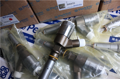
Perkins2506柴油发动机威尔逊P500E柴油发电机配件CH11945喷油器
详细描述
项目 零配件号码 新件号 描述
1 CH11945 6 CH11945 喷油器
6 CH10790 6 CH10790 摇臂座
7 CH10791 6 CH10791 螺拴
8 CH10792 6 CH10792 间隔器

项目 零配件号码 新件号 描述
2 KRP1643 1 KRP1643 密封垫装备

项目 零配件号码 新件号 描述
1 CH10933 1 CH10933 飞轮壳
2 CH11304 1 CH11304 密封垫 -后油封
2 CH10782 1 CH11304 密封垫 -后油封
3 CH10539 1 CH10539 堵塞盖
4 CH10540 1 CH10540 密封垫
5 CH10538 1 CH10538 螺拴
6 CH10541 2 CH10255 垫圈
7 CH10537 1 CH11895 螺拴
8 CH10262 2 CH10262 栓塞
9 CH10783 9 CH10783 螺拴
10 CH10099 9 CH10099 垫圈
11 CH10586 15 CH10586 螺拴
12 CH10541 15 CH10255 垫圈
13 CH10939 1 CH10939 排泄栓塞
14 CH10940 1 CH10940 密封垫

项目 零配件号码 新件号 描述
1 CH12807 1 CH12807 启动马达
1 CH11089 1 CH12807 启动马达
1 CH11089 1 CH12807 启动马达
1 CH12405 1 CH12807 启动马达
1 CH12405 1 CH12807 启动马达
(1) CH12807 1 CH12807 启动马达

项目 零配件号码 新件号 描述
1 CH11024 1 CH11024 紧张臂
1 CH11024 1 CH11024 紧张臂
17 CH10813 4 CH10813 螺拴
18 ST15903 4 ST15903 垫圈

项目 零配件号码 新件号 描述
2131 A012 2 2131 A012 垫圈
2318 A210 2 2318 A210 螺帽
CH11444 2 CH11444 滚珠轴承
2 1 壳
3 CV17729 1 CV17729 轴
4 CV17731 1 CV17731 垫圈
5 CV5324 1 CV5324 螺帽
6 CH11444 1 CH11444 滚珠轴承
7 CV17765 1 CV17765 套筒
8 CV17732 1 CV17732 拉紧带轮
9 CH11444 1 CH11444 滚珠轴承
10 2722 A022 1 2722 A022 CIRCLIP
11 2721351 1 2721351 CIRCLIP
12 CV19793 1 CV19793 螺拴
13 2131 A012 1 2131 A012 垫圈
14 2131 A012 1 2131 A012 垫圈
15 2318 A210 1 2318 A210 螺帽
16 2318 A210 1 2318 A210 螺帽

项目 零配件号码 新件号 描述
1 CH12832 1 T400228 紧张臂
18 CH10813 4 CH10813 螺拴
19 ST15903 4 ST15903 垫圈

项目 零配件号码 新件号 描述
2 1 紧张
3 CH12834 1 CH12834 衬套
4 1 轴
5 1 螺拴
6 2131 A012 1 2131 A012 垫圈
7 2131 A012 1 2131 A012 垫圈
8 2318 A210 1 2318 A210 螺帽
9 2318 A210 1 2318 A210 螺帽
10 1 垫圈
11 CH11444 1 CH11444 滚珠轴承
12 1 螺帽
13 1 套筒
14 2722 A022 1 2722 A022 CIRCLIP
15 CH11444 1 CH11444 滚珠轴承
16 2721351 1 2721351 CIRCLIP
17 CH12872 1 T400228 拉紧带轮

项目 零配件号码 新件号 描述
1 T400228 1 T400228 紧张臂

项目 零配件号码 新件号 描述
2 1 壳
3 CH12834 1 CH12834 衬套
4 1 轴
5 1 螺拴
6 CH11604 1 CH11604 垫圈
7 CH11604 1 CH11604 垫圈
8 T400231 1 T400231 螺帽
9 T400231 1 T400231 螺帽
10 1 垫圈
11 1 螺帽
12 1 套筒
13 CH11444 2 CH11444 滚珠轴承
14 CH12872 1 T400228 拉紧带轮
15 T400229 1 T400229 CIRCLIP
16 T400230 1 T400230 CIRCLIP

项目 零配件号码 新件号 描述
CH10255 6 CH10255 垫圈
ST44456 6 ST44456 螺拴
1 CH12009 1 CH12009 风扇
2 1 风扇承接器

项目 零配件号码 新件号 描述
1 CH11197 1 检查历史 FANDRIVE
10 CH11033 2 CH11033 图钉
11 0920007 2 0920007 垫圈
12 2238155 2 2238155 螺帽

项目 零配件号码 新件号 描述
2 1 检查历史 风扇驾驶壳
3 CH11175 1 检查历史 风扇驾驶皮带轮
4 ST49004 1 ST49004 CIRCLIP
5 CH11032 1 检查历史 帽
6 ST43563 2 ST43563 螺拴
7 2131 A010 2 2131 A010 垫圈
8 CH11090 1 检查历史 驱动轴
9 CH11027 1 检查历史 辊轴承

项目 零配件号码 新件号 描述
1 CH12386 1 CH12386 FANDRIVE
1 CH12386 1 CH12386 FANDRIVE
18 CH12433 1 CH12433 圈
19 2315 C066 6 2315 C066 螺旋

项目 零配件号码 新件号 描述
2 CH12391 1 CH12391 轴
3 1 风扇驾驶壳
4 CH12908 1 CH12908 放泄阀
4 CH12376 1 CH12908 放泄阀
5 CH12387 1 CH12387 风扇驾驶皮带轮 223.5
6 CH12374 1 CH12374 球
7 CH12378 1 CH12378 密封垫
8 CH12379 1 CH12379 间隔器
9 CH12382 1 CH12382 滚珠轴承
10 CH12383 1 CH12383 间隔器
11 CH12375 1 CH12375 滚珠轴承
12 CH12384 1 CH12384 密封O型圈
13 CH12380 1 CH12380 垫圈
14 CH12377 2 CH12377 螺拴
15 CH12390 1 CH12390 承接器
16 CH10585 6 CH10585 螺拴
17 CH10220 1 CH10220 栓塞

项目 零配件号码 新件号 描述
1 CH10789 1 CH10789 框
2 CH11895 5 CH11895 螺拴
3 CH10255 5 CH10255 垫圈
4 CH10550 2 CH10550 螺拴
4 CH10537 5 CH11895 螺拴
4 CH10541 2 CH10255 垫圈
5 CH10255 2 CH10255 垫圈
6 CH10968 1 CH10968 管 - 油的吸入
7 CH11905 1 CH11905 密封O型圈
7 CH10787 1 CH10787 密封O型圈
8 CH10855 1 CH10855 支撑托架
9 CH10785 2 CH10785 锁紧螺母
10 CH10786 1 CH10786 油管
11 CH11906 1 CH11906 密封O型圈
11 CH10788 1 CH10788 密封O型圈
12 CH11645 2 CH11645 螺拴
13 CH10615 2 CH10615 垫圈
14 CH11645 1 CH11645 螺拴
15 CH10615 1 CH10615 垫圈

项目 零配件号码 新件号 描述
1 CH11846 1 CH11846 油底壳
1 CH11846 1 CH11846 油底壳

项目 零配件号码 新件号 描述
2 CH10887 1 CH10887 密封垫 -油底壳
3 CH10944 20 CH10944
4 CH10992 2 CH10992 排泄栓塞
5 ST49857 2 ST49857I 垫圈
6 CH11455 2 CH11455 油底壳承接器
7 CH10228 2 CH10228 密封O型圈
8 CH11459 2 CH11459 UNF 螺帽
9 CH12757 2 CH12757 油底壳排泄栓塞
9 CH10991 2 CH10991 排泄栓塞
10 CH11573 2 CH11573 密封O型圈
10 ST49950 2 ST49950 垫圈
11 CH11456 2 CH11456 承接器
12 CH10316 2 CH10316 密封O型圈
13 CH11460 2 CH11460 UNF 螺帽

Before
Starting Engine
be installed if the engine must be started in order
to perform service procedures. To help prevent an
accident that is caused by parts in rotation, work
around the parts carefully.
The initial start-up of an engine that is new, serviced
or repaired make provision to shut the engine
off, in order to stop an overspeed. This may be
accomplished by shutting off the air and/or fuel
supply to the engine.
Overspeed shutdown should occur automatically for
engines that are controlled electronically. If automatic
shutdown does not occur, press the emergency stop
button in order to cut the fuel and/or air to the engine.
Inspect the engine for potential hazards.
Before starting the engine, ensure that no one is on,
underneath, or close to the engine. Ensure that the
area is free of personnel.
If equipped, ensure that the lighting system for the
engine is suitable for the conditions. Ensure that all
lights work correctly, if equipped.
All protectiv e guards and all protective covers must
be installed if the engine must be started in order
to perform s ervice procedures. To help prevent an
accident that is caused by parts in rotation, work
around the parts carefully.
Do not bypass the automatic shutoff circuits. Do not
disable the automatic shutoff circuits. The circ uits are
provided in order to help prevent personal injury. The
circuits are also provided in order to help prevent
engine damage.
See the Service Manual for repairs and for
adjustments .
i02583384
Engine Starting
Do not use aerosol types of starting aids such as
ether. Such use could result in an explosion and
personal injury.
If a warning tag is attac hed to the engine start switch
or to the c ontrols DO NOT start the engine or move
the controls. Consult with the person that attached
the warning tag before the engine is started.
Start the engine from the operator’s compartment or
from the engine start switch.
Always start the engine according to the procedure
that is described in the Operation and Maintenance
Manual, “Engine Starting” topic in the Operation
Section. Knowing the correct procedure will help to
prevent major damage to the engine components.
Knowing the procedure will also help to prevent
personal injury.
To ensure that the jacket water heater (if equipped)
is working correctly, check the water temperature
gauge and/or the oil temperature gauge during the
heater operation.
Engine exhaust contains products of combustion
which can be harmful to your health. Always start the
engine and operate the engine in a well ventilated
area. If the engine is started in an enclosed area,
vent the engine exhaust to the outside.
Note: The engine may be equipped with a device for
cold starting. If the engine will be operated in very
cold conditions, then an extra cold starting aid may
be required. Normally, the engine will be equipped
with the correct type of starting aid for your region
of operation.
i01462046
Engine Stopping
Stop the engine according to the procedure in
the Operation and Maintenance Manual, “Engine
Stopping (Operation Section)” in order to avoid
overheating of the engine and accelerated wear of
the engine components.
Use the Emergency Stop Button (if equipped) ONLY
in an emergency situation. Do not use the Emergency
Stop Button for normal engine stopping. After an
emergency stop, DO NOT start the engine until the
problem that caused the emergency stop has been
corrected.
Stop the engine if an overspeed condition occurs
during the initial start-up of a new engine or an engine
that has been overhauled. This may be accomplished
by shutting off the fuel supply to the engine and/or
shutting off the air supply to the engine.
This document has been printed from SPI². Not for Resale

![]()
![]()
![]() 12
12
Safety Section
Electrical System
SEBU8313
To stop an electronically controlled engine, cut the
power to the engine.
Grounding Practices
Electrical
System
i02469632
Never disconnect any charging unit circuit or battery
circuit cable from the battery when the charging unit
is operating. A spark can cause the combus tible
gases that are produced by some batteries to ignite.
To help prevent sparks from igniting combustible
gases that are produced by some batteries, the
negative “ ” jump start cable should be connected
last from the external power source to the negative
“ ” terminal of the starting motor. If the starting motor
is not equipped with a negative “ ” terminal, connect
the jump start cable to the engine block .
Check the electrical wires daily for wires that are
loose or frayed. Tighten all loose electrical wires
before the engine is started. Repair all frayed
electrical wires before the engine is started. Refer to
the “Engine Starting” section of this Operation and
Maintenance Manual for specific starting instructions.
Illustration 9
Typical example
Grounding Stud To Battery Ground
g00771448
This document has been printed from SPI². Not for Resale

![]()
![]()
![]()
![]()
![]() SEBU8313
SEBU8313
13
Safety Section
Engine Electronics
Engine
Electronics
i02583382
Illustration 10
Typical example
Alternate Grounding Stud To Battery Ground
g00771487
Tampering with the electronic system installation
or the OEM wiring installation can be dangerous
and could result in personal injury or death and/or
engine damage.
This engine has a comprehensive, programmable
Engine Monitoring System. The Engine Control
Module (ECM) has the ability to monitor the engine
operating conditions. If any of the engine parameters
extend outside an allowable range, the ECM will
initiate an immediate action.
The following actions are available for engine
monitoring control: WARNING, ACTION ALERT, and
SHUTDOWN.
Many of the parameters that are monitored by the
ECM can be programmed for the engine monitoring
functions. The following parameters can be monitored
as a part of the Engine Monitoring System:
• Atmospheric Pressure
• Inlet Manifold Pressure
Proper grounding for the engine elec trical system
is necessary for optimum engine performance
and reliability. Improper grounding will result in
uncontrolled electrical circuit paths and in unreliable
electrical circuit paths.
Uncontrolled electrical circuit paths can result in
damage to main bearings, to crankshaft bearing
journal surfaces, and to aluminum components.
Engines that are installed without engine-to-frame
ground straps can be damaged by electrical
discharge.
To ensure that the engine and the engine electrical
systems function properly, an engine-to-frame ground
•
•
•
•
•
•
•
Coolant Temperature
Engine Oil Pressure
Crankshaft Position
Cams haft Position
Fuel Temperature
Inlet Manifold Temperature
System Voltage
strap with a direc t path to the battery must be used.
This path may be provided by way of a starting motor
ground, a starting motor ground to the frame, or a
direct engine ground to the frame.
All grounds should be tight and free of corrosion. The
engine alternator must be grounded to the negative
“-” battery terminal with a wire that is adequate to
handle the full charging current of the alternator.
The Engine Monitoring package can vary for different
engine models and different engine applications.
However, the monitoring system and the engine
monitoring control will be similar for all engines.
This document has been printed from SPI². Not for Resale

![]()
![]()
![]()
![]()
![]()
![]()
![]() 14
14
Product Information Section
General Information
SEBU8313
Product
Section
Information
General
Information
Welding
on
Engines
with
i01889424
Electronic
Controls
Proper
NOTICE
welding procedures are
necessary
in order
to avoid damage to the engine’s ECM, sens ors, and
associated components. When possible, remove the
component from the unit and then weld the compo-
nent. If removal of the component is not possible,
the following procedure must be followed when you
Illustration 11
g00765012
weld with a unit that is equipped with an Electronic
Engine. The following procedure is considered to be
the safest procedure to weld a component. This pro-
cedure should provide a minimum risk of damage to
electronic c omponents.
NOTICE
Do not ground the welder to electrical components
such as the ECM or sensors. Improper grounding can
cause damage to the drive train bearings, hydraulic
components, electrical components, and other com-
ponents.
Clamp the ground cable from the welder to the com-
ponent that will be welded. Place the clamp as close
as possible to the weld. This will help reduce the pos-
sibility of damage.
1. Stop the engine. Turn the switched power to the
OFF position.
2. Disconnect the negative battery cable from the
battery. If a battery disconnec t switch is provided,
open the switch.
3. Disconnect the J1/P1 connectors from the ECM.
Move the harness to a position that will not allow
the harness to accidentally move back and make
contact with any of the ECM pins.
Use the example above. The current flow from the welder to
the ground clamp of the welder will not cause damage to any
associated components.
(1) Engine
(2) Welding rod
(3) Keyswitch in the OFF position
(4) Battery disconnect switch in the open position
(5) Disconnected battery c ables
(6) Battery
(7) Electrical/Electronic component
(8) Maximum distance between the component that is being
welded and any electrical/electronic component
(9) The component that is being welded
(10) Current path of the welder
(11) Ground clamp for the welder
4. Connect the welding ground c able directly to the
part that will be welded. Place the ground cable as
clos e as possible to the weld in order to reduce the
possibility of welding current damage to bearings,
hydraulic components, electrical components, and
ground straps.
Note: If electrical/electronic components are used
as a ground for the welder, or electrical/electronic
components are located between the welder ground
and the weld, current flow from the welder could
severely damage the component.
5. Protect the wiring harness from welding debris
and spatter.
6. Use standard welding practices to weld the
materials.
This document has been printed from SPI². Not for Resale

![]()
![]()
![]() SEBU8313
SEBU8313
15
Product Information Section
Model Views
Model
Views
Model View Illustrations
i02572859
The following model views show the 2506 Engine
features. Due to individual applic ations, your engine
may appear different from the illustrations.
Illustration 12
Typical example
Left side view
(1) Front timing gear housing
(2) Fuel priming pump
(3) Electronic Control Module (ECM)
(4) Flywheel housing
(5) Fuel filters
(6) Fuel transfer pump
(7) Vibration Damper
g01289036
This document has been printed from SPI². Not for Resale

| |||||||||||||||
Product Information Section
Model Views
SEBU8313
Illustration 13
Typical example
Right side view
(8) Exhaust manifold
(9) Turbocharger
(10) Temperature regulator housing
(11) Water pump
(12) Oil cooler
(13) Oil filter
g01289038
Engine
Table 1
Description
i02581540
The electronic engines that are covered by this
manual have the following characteristics: direct fuel
injection, electronic unit injection that is mechanically
actuated, turbocharged, and air-to-air aftercooled
(ATAAC).
The electronic engine control system provides the
following functions: electronic governing, automatic
air to fuel ratio control, injection timing control, and
system diagnostics.
An electronic governor controls the output of the unit
injectors in order to maintain the engine rpm that is
des ired.
This document has been printed from SPI². Not for Resale
![]() SEBU8313
SEBU8313
17
Product Information Section
Model Views
Very high injec
tion pressures are produced by
Engine efficiency, efficiency of emission controls, and
electronically controlled, mechanically actuated unit
injectors. The injectors combine the pumping and the
electronic fuel metering (duration and timing) during
injection. The unit injectors acc urately control smoke
limiting, white smoke, and engine acceleration rates.
There is one unit injector per cylinder. Individual unit
injectors meter the fuel. The indi, v idual unit injectors
also pump the fuel. The metering and the pumping is
done under high pressure. High injection pressures
help to reduce fuel consumption and emissions.
The use of this type of unit injector provides total
electronic c ontrol of injection timing. The injection
timing varies with engine operating conditions. The
engine performance is optimized in the following
areas:
• Starting
• Emissions
• Noise
• Fuel consumption
The timing advance is achieved through precise
control of the injector firing. Engine speed is
controlled by adjusting the firing duration. The
information is provided to the Electronic Control
Module (ECM) by the crankshaft position sensor and
the c amshaft position sensor. The information is for
detection of cylinder position and engine speed.
The engines have built-in diagnostics in order to
ensure that all of the components are functioning
and operating properly. In the event of a system
component deviation from the programmed limits,
the operator will be alerted to the condition by a
DIAGNOSTIC lamp that is mounted on the control
panel. An electronic service tool that is provided by
Perkins may be used to read the numerical code of
the diagnostic flash code. There are three types of
diagnostic codes: ACTIVE, LOGGED, and EVENT.
These codes are logged and stored in the ECM.
Refer to Operation and Maintenance Manual, “Engine
Diagnostics” for additional information.
The cooling s ys tem consists of the following items:
a centrifugal pump that is driven by a gear, water
temperature regulator, an oil cooler, and a radiator
that incorporates a shunt system.
The engine lubricating oil is supplied by a gear
type pump. The engine lubricating oil is cooled and
filtered. Bypass valves provide unrestricted flow
of lubrication oil to the engine parts when the oil
viscosity is high or if either the oil cooler or the oil
filter elements (paper cartridge) become plugged.
engine performance depend on adherence to proper
operation and maintenance recommendations. This
includes the use of recommended fuels, coolants
and lubrication oils.
Aftermarket Products and Perkins
Engines
When auxiliary devices, accessories, or consumables
(filters, additives, c atalysts, etc) which are made by
other manufacturers are used on Perkins products,
the Perkins warranty is not affected simply because
of such use.
However, failures that result from the installation
or use of other manufacturers’ devices,
accessories, or consumables are NOT Perkins
defects. Therefore, the defects are NOT covered
under the Perkins warranty.
This document has been printed from SPI². Not for Resale

![]()
![]()
![]() 18
18
Product Information Section
Product Identification Information
SEBU8313
Product
Identification
Information
Plate
Locations
and
Film
i02578572
Locations
Illustration 14
(1) Serial number plate
Perkins engines are identified by serial numbers.
These numbers are shown on the engine serial
number plate. Perkins distributors need these
numbers in order to determine the components that
were included with the engine. This permits accurate
identific ation of replacement part numbers.
Serial Number Plate (1)
The engine serial number plate is located on the
lower right side of the engine block.
g01291895
Engine serial number _____________________________________
Designation _________________________________________________
Engine Rating ______________________________________________
This document has been printed from SPI². Not for Resale
![]() SEBU8313
SEBU8313
19
Product Information Section
Product Identification Information
Reference
Numbers
i02563635
Information for the following items may be needed to
order parts. Locate the information for your engine.
Record the information in the appropriate space.
Mak e a copy of this list for a record. Keep the
information for future reference.
Record for Reference
Engine Model _______________________________________________
Engine Serial number _____________________________________
Engine rpm __________________________________________________
Primary Fuel Filter _________________________________________
Secondary Fuel Filter Element __________________________
Lubrication Oil Filter Element ___________________________
Total Lubrication System Capacity _____________________
Total Cooling System Capacity _________________________
Air Cleaner Element _______________________________________
Fan Drive Belt ______________________________________________
Alternator Belt ______________________________________________
This document has been printed from SPI². Not for Resale

![]()
![]()
![]() 20
20
Product Information Section
Product Identification Information
SEBU8313
i02576079
Emissions Certification Film
Label for compliant engines
Illustration 15
Typical example of a label that is installed on engines that comply with emissions
g01290846
This document has been printed from SPI². Not for Resale

![]()
![]()
![]() SEBU8313
SEBU8313
21
Product Information Section
Product Identification Information
Illustration 16
Typical example of a label that is installed on engines that comply with emissions
g01290859
Customer
Specified
i02566844
•
•
Inlet Manifold Temperature Sensor
Coolant Temperature Sensor
Parameters
To rec ord programmed specifications, use the
following blanks.
Customer Passwords (If required).
• First Password ___________________________________________
• Second Password ______________________________________
Rating Selection (L-N) __________________________________
Equipment ID ______________________________________________
Programmable Monitoring System
(PMS)
The Programmable Monitoring System determines
the level of action that is taken by the ECM in
response to a condition that can damage the engine.
These conditions are identified by the ECM from the
signals that are produced from the following sensors.
•
•
•
•
Engine Oil Pressure Sensor
Engine Crankshaft/Camshaft Sensors
Inlet Manifold Pressure Sensor
Fuel Temperature Sensor
This document has been printed from SPI². Not for Resale

![]() 22
22
Product Information Section
Product Identification Information
SEBU8313
Table 2
Event Code
E162
-1
Parameter
High Boost Pres sure
Warn Operator (1)
On
State
Trip Point
300 kPa (43.5 psi)
Delay Time
30 seconds
-2
E360
-1
-2
-3
E361
-1
-2
-3
E362
-1
-2
-3
E363
-1
-2
Action Alert (2)
Low E ngine Oil Pressure
Warn Operator (1)
Action Alert (2)
Engine Sh utdown (3)
High Engine Coolant Tempera ture
Warn Operator (1)
Action Alert (2)
Engine Sh utdown (3)
Engine Overspeed
Warn Operator (1)
Action Alert (2)
Engine Sh utdown (3)
High Fuel Supply Temperature
Warn Operator (1)
Action Alert (2)
Always On
On
Always On
Always On
On
Always On
Always On
On
Always On
Always On
On
Always On
None
300 kPa (43.5 psi)
None
None
104 °C (2190 °F)
105 °C (221 °F)
108 °C (226 °F)
2000 RPM
2050 RPM
2140 RPM
60 °C (140 °F)
68 °C (154 °F)
5 seconds
60 seconds
2 seconds
2 seconds
60 seconds
10 seconds
10 seconds
1 second
1 second
0 second
60 seconds
60 seconds
E368
-1
-2
High Engine Intake Ma nifold Air Temperature
Warn Operator (1) On
Action Alert (2) Always On
75 °C (167 °F)
78 °C (172 °F)
60 seconds
10 seconds
Refer to Troubleshooting , “System Configuration
Parameters” for additional information for the
Programmable Monitoring Sys tem.
This document has been printed from SPI². Not for Resale