Perkins2806柴油发动机威尔逊P700E柴油发电机配件CH11087交流充电发电机供应商,Perkins2806柴油发动机威尔逊P700E柴油发电机配件CH11087交流充电发电机技术价格规格咨询服务,Perkins2806柴油发动机威尔逊P700E柴油发电机配件CH11087交流充电发电机零配件供应,Perkins2806柴油发动机威尔逊P700E柴油发电机配件CH11087交流充电发电机售后服务中心,Perkins2806柴油发动机威尔逊P700E柴油发电机配件CH11087交流充电发电机,Perkins2806柴油发动机威尔逊P700E柴油发电机配件CH11087交流充电发电机详细的技术参数,

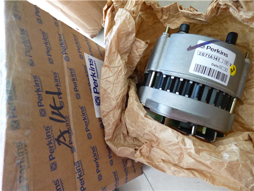
Perkins2806柴油发动机威尔逊P700E柴油发电机配件CH11087交流充电发电机
详细描述
项目 零配件号码 新件号 描述
1 CH11087 1 CH11087 交流充电发电机
(1) CH11087 1 CH11087 交换交流充电发电机

项目 零配件号码 新件号 描述
2 1 交流充电发电机
3 CH12877 1 CH12877 交流充电发电机皮带轮

项目 零配件号码 新件号 描述
1 CH11625 1 CH11625 管 - 涡轮增压器的油补给
2 CH11563 1 CH11563 管夹
3 CH10776 1 CH10776 间隔器
4 CH10538 1 CH10538 螺拴
5 CH10255 1 CH10255 垫圈
5 CH10541 1 CH10255 垫圈

项目 零配件号码 新件号 描述
1 CH11627 1 CH11627 管 - 涡轮增压器的油排泄
2 CH11561 1 CH11561 密封垫
3 CH11565 2 CH11565 螺拴
4 CH10585 2 CH10585 螺拴
5 CH10277 2 CH10277 垫圈
6 CH11624 1 CH11624 肘管
7 CH11560 1 CH11560 密封垫
8 CH11562 1 CH11562 密封O型圈
9 1 涡轮增压器

项目 零配件号码 新件号 描述
1 CH11607 1 CH11607 涡轮增压器
(1) CH11607 1 CH11607 涡轮增压器
2 CH11761 1 CH11761 密封垫 -涡轮增压器
2 CH11746 1 CH11761 密封垫
3 CH10733 4 CH10733 螺拴
4 CH10734 4 CH10734 锁紧螺母

项目 零配件号码 新件号 描述
1 CH11556 1 CH11556 排出岐管
2 CH11557 1 CH11557 排出岐管
3 CH11555 12 CH11555 间隔器
4 CH10775 12 CH10775 图钉
5 CH10734 12 CH10734 锁紧螺母
6 CH12340 6 CH12340 套筒
6 CH11882 6 CH12340 密封垫 - 排出岐管

![]() 2800 Series
2800 Series
Engine emergency stop
3
Caution: Emergency shut-off controls are for emergency use only. Do not use emergency shut-off devices or
controls for the normal stop proc edure.
Ens ure that any components for the external system that support the engine operation are secured after the
engine is stopped.
Manual stop procedure
Individual applications will have different control systems. Ensure that the engine shut-down procedures are
understood. To stop the engine, use the general guidelines which follow:
1 Run the engine with no load for five minutes to allow it to cool.
2 After the cool-down period, turn the start switch to the OFF position.
User’s Handbook, TPD1516E, Issue 1
11
This document has been printed from SPI². Not for Resale
![]() 3
3
Engine diagnostics
Self-diagnostics
2800 Series
Perkins electronic engines can perform a self-diagnostics test. Diagnostic codes are stored in the permanent
memory of the Electronic Control Module (ECM) and can be retrieved by use of the Perkins electronic service
tool, EST. A list of diagnostic codes is given in the table under "Diagnostic codes" on page 20.
Some installations have electronic dis plays that provide a direct reading of the engine diagnostic codes. Refer
to the manual that is provided by the OEM for more information on retrieving engine diagnostic codes.
Active codes, indic ated by a warning lamp or similar device (depending on application), represent problems
that currently exist. These problems should be investigated first.
Logged codes repres ent:
Intermittent problems
Recorded events
Performance history
The problems may have been repaired since the code was logged. These codes do not indicate that a repair
is needed; the codes are guides or signals when a situation exists. Codes may be helpful to diagnose
problems.
When the problems have been corrected, the corresponding logged fault codes should be cleared, where
possible.
Use the Perkins service tool EST to determine the diagnostic code.
Fault logging
The system provides the capability of fault logging. When the Electronic Control Module (ECM) generates a
diagnostic c ode, the code will be logged in the memory of the ECM. The codes that have been logged in the
memory of the ECM can be retrieved with Perkins electronic service tools. The codes that have been logged
can be cleared with Perkins electronic service tools. The codes that have been logged in the memory of the
ECM will be automatically cleared from the memory after 100 hours. If the engine is operated in protection
override mode, then low engine oil pressure and high engine coolant temperature events cannot be cleared
without a factory password.
Engine operation with active diagnostic codes
If a fault is indicated during normal engine operation, the system has identified a situation that is not within the
specification. Use Perkins electronic service tools to check the active diagnos tic codes.
The active diagnostic code should be inv estigated. The cause of the problem should be corrected as soon as
possible. If the cause of the active diagnostic code is repaired, and there was only one active diagnostic code,
the warning lamp or similar device will turn off.
Engine operation with intermittent diagnostic codes
If during normal engine operation a fault is indicated by a fault lamp or similar device and the lamp or device
then returns to normal, an intermittent fault may have occurred. If a fault has occurred, the fault will be logged
in the memory of the Electronic Control Module (ECM).
In most cases, it is not necessary to stop the engine because of an intermittent code. However, the operator
should retrieve the codes and refer to the relevant information to identify the nature of the event. The operator
should note the circumstances that are involved during the time that the lamp was on:
Engine load
Limits of the engine speed
Excessive smoke, etc.
This information can be useful to help diagnose the situation. The information can also be used for future
reference. For more information on diagnostic codes, refer to the Diagnostic Manual for this engine.
12
User’s Handbook, TPD1516E, Issue 1
This document has been printed from SPI². Not for Resale
![]() 2800 Series
2800 Series
Customer specified parameters
3
Customer specified parameters that will enhance the fuel efficiency and the operator's convenience can be
programmed into the Electronic Control Module (ECM). Some parameters may affect engine operation. This
may lead to complaints from the operator about power or performance. The engine related parameters which
follow may be programmed by the customer, by use of the Perkins electronic service tool, to influence the
operation of the engine:
Engine ratings selection, the ability to choose between the relevant torque maps
(prime/stand-by, 50/60 Hz) (where a switchable flash file has been specified)
Governor gain tuning parameters
Analogue throttle enable
Equipment identification
Droop set point
Engine acceleration rate
Enable speed selection by the use of an external switch
Enable droop/isochronous selection by the use of an external switch
User’s Handbook, TPD1516E, Issue 1
13
This document has been printed from SPI². Not for Resale
This page is intentionally blank
This document has been printed from SPI². Not for Resale
![]()
|
Preventive maintenance
Preventive maintenance periods
4
These preventive maintenance periods apply to average conditions of operation. Chec k the periods given by
the manufacturer of the equipment in which the engine is ins talled. Use the periods which are shortes t. When
the operation of the engine must conform to the local regulations thes e periods and procedures may need to
be adapted to ensure c orrect operation of the engine.
It is good preventive maintenance to c heck for leakage and loos e fasteners at each service.
These maintenance periods apply only to engines that are operated with fuel and lubricating oil which conform
to the specifications given in this handbook.
User’s Handbook, TPD1516E, Issue 1
15
This document has been printed from SPI². Not for Resale
![]() 4
4
Schedule
2800 Series
The maintenance operations must be applied at the interval (hours or months)which occurs first.
A Daily E E very 3000 hour s o r 24 months
B Every 250 hours or 12 month s F E very 3000 h our s o r 36 months
C Every 500 hours or 12 month s G E very 5000 h ours
D Every 1000 hours or 24 months
|
A B |
C D |
E F |
G Operation |
|
Check the c oolant level | |||
|
Check the air cleaner service indicator | |||
|
Check the lubricating oil level | |||
|
Drain water/sediment from the pr imary fuel filter | |||
|
Visual inspec tion of the engine systems | |||
|
Drain water/sediment from the fuel tank | |||
|
Check battery electrol yte level | |||
|
Perform a diagnostics check | |||
|
Renew the element in the primar y fuel filte r | |||
|
Renew the element in the se condary fue l fil ter | |||
|
Renew the engine lubricating oil (1) (2) | |||
|
Renew the element in the lubricating oil filter | |||
|
Inspect/adjus t/renew the alternator and fan drive belts | |||
|
Inspect the crankshaft vibration damper | |||
|
Inspect/clean/tighten the earth stud | |||
|
Inspect/renew the coolant hoses, air hos es and hos e clips | |||
|
Inspect and, if necessary, clean the exterior of the radiator/charge cooler | |||
|
Inspect the engine mountings | |||
|
Check/adjust the tappet clearances and the electronic unit injectors (3) | |||
|
Check the engine protection devices (3) | |||
|
Renew the thermostats in the cool ant system | |||
|
Check/clean the engine speed/timing senso rs | |||
|
Inspect the tur bochargers (3) | |||
|
Drain and flush the coolant system and r enew the coolant mixture | |||
|
Inspect the battery charging alternator (3) | |||
|
Inspect the starter motor (3) | |||
|
Inspect the coolant p ump |
(1) Oil sample analysis may be used to monitor the condition of the lubricating oil, but the lubricating oil must be replaced at
500 hours/12 months.
(2) If fuel with a high sulphur content is used, the lubricating oil may have to be replaced at more frequent intervals. Contact the
Applic ations Department (Stafford) at Perkins Engines Company Limited.
(3) This proc edure must be done by a person who has had the correct training.
16
User’s Handbook, TPD1516E, Issue 1
This document has been printed from SPI². Not for Resale

![]() 2800 Series
2800 Series
How to check the coolant level
Chec k the coolant level when the engine is s topped and cool.
Warning! On a hot engine release the filler cap c arefully as the system will be under pressure.
1 Remove the filler cap from the expansion tank slowly to relieve the pressure.
2 Maintain the coolant level at the bottom of the filler pipe.
4
3 Clean the filler cap and check the condition of the filler cap gaskets. Renew the filler cap if the gaskets are
damaged. Fit the filler cap.
4 Inspect the coolant system for leaks.
How to check the air cleaner service indicator
Caution: Do not operate the engine if there is a blockage in the air filter or the air ducts. This can c ause
lubricating oil to enter the cylinders through the engine breather pipe.
The air filter is fitted with a restric tion indicator (A) whic h gives a visual warning when the filter needs a service.
When the red warning indicator is seen through the clear panel after the engine has stopped, the air filter
element must be renewed.
After a clean element has been fitted, press the reset button on the restriction indicator.
Env ironmental conditions have an important effect on the frequency at which the air filter needs to be serviced.
A
User’s Handbook, TPD1516E, Issue 1
17
This document has been printed from SPI². Not for Resale
![]() 4
4
How to check the lubricating oil level
2800 Series
Warning! Hot oil and hot components can cause personal injury. Do not allow hot oil or hot components to
contact the skin.
At the periods given in the service schedule use the dipstick to check the amount of lubricating oil in the sump.
1 Check the oil level with the engine stopped. The level must be maintained between the “L” mark and “H”
mark on the dipstick.
2 If necessary, remove the oil filler cap and add lubricating oil of the same grade and spec ification, see
"Lubricating oil spec ification" on page 52. Do not overfill.
3 Clean and fit the oil filler cap.
How to drain the primary fuel filter
At the periods given in the service schedule, the bowl of the primary fuel filter must be drained to remove water.
1 Stop the engine.
2 Open the drain; the drain is self-ventilated. Use a suitable container to collect the water drained from the
filter housing. Dispose of the water safely.
3 Close the drain. Tighten the drain valve securely to prevent air from entering the fuel system.
18
User’s Handbook, TPD1516E, Issue 1
This document has been printed from SPI². Not for Resale
![]() 2800 Series
2800 Series
Visual inspection
A visual inspection should take only a few minutes and can prevent costly repairs and accidents.
4
For maximum engine life, inspect the engine compartment before the engine is started. Look for items such
as oil or coolant leaks, loose fastenings, worn belts or loose connections. Repair as necessary .
The guards must be at the correct positions. Repair damaged guards or renew missing guards.
Wipe all caps and plugs before the engine is serviced to reduce the chance of system contamination.
For any type of leak (coolant, lubricating oil or fuel), clean away the fluid. If a leak is observed, find the
source and correct the leak. If a leak is suspected, check the fluid levels frequently until the leak is found
and repaired.
Accumulated grease and/or oil on an engine is a fire hazard. Remove it by steam cleaning or by the use of
a high pressure water jet. Avoid high pressure water on the elec tronic components.
Ensure that the coolant pipes are fitted correctly and that they are secure. Check for leaks. Check the
condition of all pipes.
Inspect the coolant pump for leaks.
Note: The coolant pump seal is lubricated by the coolant in the coolant system. It is normal for a small amount
of leakage to occur as the engine cools and the parts contract.
Excessive coolant leakage may indicate the need to renew the coolant pump s eal. For the removal of the
coolant pump and the installation of the coolant pump and/or coolant pump seals, refer to the Workshop
Manual.
Inspect the lubrication system for leaks at the front crankshaft seal, the rear crankshaft seal, the sump, the
oil filter and the rocker cover. If many oil leaks are present, particularly on an old engine, there could be a
blockage of the engine breather.
Inspect the fuel system for leaks. Check for loose fuel line clamps or for loose ties on the fuel lines.
Inspect the ducts for the air inlet system and the elbows for cracks. Check also for loose clamps and check
the condition of mounting rubbers. Ensure that hoses and tubes are not in contact with other hoses, tubes,
wiring harnesses , etc.
Inspect the fan belts and the alternator belt for cracks, breaks or other damage. Where more than one belt
is used between two pulleys, all of the belts must be renewed together. Maximum belt life will only be
obtained if the belts are maintained at the correct tension.
Drain the water and sediment from fuel tank s on a daily basis to ensure that only clean fuel enters the fuel
sys tem.
Inspect the wiring and the wiring harnesses for loose connections and for worn or frayed wires.
Inspect the earth strap for a good connection and for good condition.
Inspect the ECM-to-cylinder head earth strap for a good connection and for good condition.
Disconnect any battery chargers which are not protec ted against the current drain of the starter motor.
Check the condition and the electrolyte level of the batteries, unless the engine is fitted with a maintenance
free battery.
Check the condition of the gauges. Renew any gauges that are cracked. Renew any gauge that cannot be
calibrated.
User’s Handbook, TPD1516E, Issue 1
19
This document has been printed from SPI². Not for Resale
 4
4
Diagnostics check
2800 Series
At the periods specified in the service schedule, use the Perkins Electronic Service Tool to retrieve the
diagnostic codes. A key to the codes is given below. Refer to the relevant Diagnostic Manual for further details.
Diagnostic codes
CID-FMI
1-11
2-11
3-11
4-11
5-11
6-11
Injector cylinder No. 1 fault
Injector cylinder No. 2 fault
Injector cylinder No. 3 fault
Injector cylinder No. 4 fault
Injector cylinder No. 5 fault
Injector cylinder No. 6 fault
Diagnostic code description
4 1-03
4 1-04
9 1-08
100-03
100-04
110-03
110-04
168-02
172-03
172-04
174-03
174-04
190-02
190-09
190-11, 12
248-09
253-02
254-12
261-13
262-03
262-04
268-02
273-03
273-04
274-03
274-04
281-03
281-04
281-05
282-03
282-04
285-03
285-04
286-03
286-04
286-05
323-03
323-04
323-05
8 volt Sensor power supply open/short to B+
8 volt Sensor power supply short to ground
PWM Speed control abnormal
Engine oil pressure sensor open/short to B+
Engine oil pressure sensor short to ground
Engine coolant temp sensor open/short to B+
Engine coolant temp sensor short to ground
Intermittent battery power to the ECM
Intake manifold temperature sensor open/short to B+
Intake manifold temperature sensor short to ground
Fuel temperature sensor open/short to B+
Fuel temperature sensor short to ground
Engine speed sensor data intermittent
Engine speed sensor abnormal update
Engine speed sensor mechanical fault
Per kins data link communications abnormal
Check customer or system parameters
ECM Fault
Engine timing calibration required
5 volt Sensor power supply open/short to B+
5 volt Sensor power supply short to ground
Check programmable parameters
Turbo outlet pressure sensor open/short to B+
Turbo outlet pressure sensor short to ground
Atmospheric pressure sensor open/short to B+
Atmospheric pressure sensor short to ground
Action alert lamp open/short to B+
Action alert lamp short to ground
Action alert lamp open circuit
Engine overspeed lamp open/short to B+
Engine overspeed lamp short to ground
Engine coolant temperature lamp open/short to B+
Engine coolant temperature lamp short to ground
Engine lubrica ting oil pressure lamp open/short to B+
Engine lubricating oil pressure lamp short to ground
Engine lubricating oil pressure lamp open circuit
Engine shutdown lamp open/short to B+
Engine shutdown lamp short to ground
Engine shutdown lamp open circuit
20
User’s Handbook, TPD1516E, Issue 1
This document has been printed from SPI². Not for Resale

![]() 2800 Series
2800 Series
4
CID-FMI
324- 03
324- 04
324- 05
342 -02
342-11, 12
443- 03
799- 12
1266-03
1266-04
169 0-8
Diagnostic code description
Engine warning lamp open/short to B+
Engine warning lamp short to ground
Engine warning lamp open circuit
Engine speed sensor No. 2 data intermittent
Engine speed sensor No. 2 mechanical fault
Crank terminate relay open/short to B+
Service tool fault
Diagnostic lamp open/short to B+
Diagnostic lamp short to ground
Analogue throttle signal abnormal
User’s Handbook, TPD1516E, Issue 1
21
This document has been printed from SPI². Not for Resale


![]() 4
4
How to renew the element of the primary fuel filter
2800 Series
Cautions:
Do not allow dirt to enter the fuel system. Clean thoroughly the area around a fuel system component that
will be disconnected. Fit a suitable cover to any disconnected component of the fuel system.
Do not loosen fuel pipes or fittings except where indicated in this user’s handbook.
1 Stop the engine. Turn the s tart switch to the “OFF” position. Disconnect the battery.
Warning! Discard the water and fuel mixture in a safe place and in accordance with local regulations.
2 Close the fuel tank supply valve. Remove the drain plug from the base of the filter housing (A2) and drain
the water and fuel into a suitable container. Dispose of the mixture safely.
Warning! Discard the used filter element and ‘O’ ring seal in a safe plac e and in accordance with local
regulations.
3 Remove the filter housing, remove the ‘O’ ring seal from the housing and withdraw the filter element (A1).
4 Clean the inside of the housing and the housing thread with clean fuel oil and clean the contact face of the
filter head. Clean the drain plug and fit it to the housing.
Notes:
If a degreasing agent has been used to clean the housing, a suitable anti-seize lubricant must be applied
to the threads before the housing is fitted.
The correct filter element will be marked with the symbol shown (B).
Continued
22
User’s Handbook, TPD1516E, Issue 1
This document has been printed from SPI². Not for Resale

![]() 2800 Series
2800 Series
4
5 Fit a new element (A1) into the housing (A2). Ensure that the element engages fully with the guide in the
base of the housing. Fit a new ‘O’ ring seal to the top of the housing.
Cautions:
It is important that only genuine Perkins parts are used. The use of non Perkins parts could damage the
fuel injection equipment.
Do not fill the primary fuel filter with fuel before installation. The fuel would not be filtered and could be
contaminated. Contaminated fuel will c ause accelerated wear to components of the fuel system.
6 Fit the housing onto the filter head. Tighten the housing to a torque of 80 Nm (59 lbf ft) 8.16 kgf m. Do not
overtighten. Ensure that the drain plug is tightened securely .
7 Clean away any fuel which has been spilled.
8 Open the fuel tank supply valve and eliminate air from the fuel system, see "How to eliminate air from the
fuel system" on page 49.
9 Check for leaks.
User’s Handbook, TPD1516E, Issue 1
23
This document has been printed from SPI². Not for Resale