English
 Espaol
 Franais
 阿拉伯
阿拉伯 中文
中文 Deutsch
 Italiano
 Português
 日本
日本 韩国
韩国 български
 hrvatski
 esky
esky Dansk
Dansk Nederlands
 suomi
suomi Ελληνικ
 印度
印度 norsk
norsk Polski
 Roman
Roman русский
 Svenska
农业
1450CWS
6630
1450WTS
6830
1470
6930
1550CWS
7130
1550WTS
7230
1654
7330
1854
7430
2054
W330
6225
6525
6530

| 设备型号 | 备注 |
|---|---|
| 570A | Small pin, O'rings on block, Con Rod (m): T20007, R81410, Piston (m): RE53265, T30015, AR78310 |
| 770CH II | Piston (m) RE521616 Tier 2 & Tier 3 |
| 772CH | Piston (m) RE515037 Tier 2 & Tier 3 |
| 672B | Liter designated |
| 770D | Piston (m) RE515037 Tier 2 & Tier 3 |
| 772 CH | High Compression Piston. To ESN 199,999. Tier 1 |
| 772A | Con Rod (m) R48315, R53287, R58883, R66926 |
| 772CH | Piston (m) RE507758 Tier 2 & Tier 3 |
| 672GP | 9.0 Liter Tier 2 & Tier 3 |
| 570A | Large pin, O'rings on block, Con Rod (m): RE16495, Piston (m): AR77762 |
| 770D | Piston (m) RE521616 Tier 2 & Tier 3 |
| 772CH II | Piston (m) RE515037 Tier 2 & Tier 3 |
| 770A | Con.Rod (m) R71074 (P/N AR93341) |
| 772CH | Piston (m) RE515037 Tier 2 & Tier 3 |
| 772 D | High Compression Piston. To ESN 199,999. Tier 1 |
| 670C | Piston (m) RE59277, RE505100 |
| 772CH II | Piston (m) RE507758 Tier 2 & Tier 3 |
| 770G | 9.0 Liter Tier 2 & Tier 3 |
| 570B | Con Rod (m): R80034, Piston (m): RE30250 |
| 772CH | Piston (m) RE521616 Tier 2 & Tier 3 |
| 772D | Piston (m) RE515037 Tier 2 & Tier 3 |
| 770B | Con.Rod (m) R71074 (P/N AR93341) |
| 772CH II | Piston (m) RE515037 Tier 2 & Tier 3 |
| 870 D | High Compression Piston. To ESN 199,999. Tier 1 |
| 670CH | Piston (m) RE59277, RE505100 |
| 772D | Piston (m) RE507758 Tier 2 & Tier 3 |
| 770GP | 9.0 Liter Tier 2 & Tier 3 |
| 570B | Liter designated, Con Rod (m): R80034, Piston (m): RE30250 |
| 772CH II | Piston (m) RE521616 Tier 2 & Tier 3 |
| 870D | Piston (m) RE515037 Tier 2 & Tier 3 |
| 770A | Con Rod (m) R71074 (P/N AR93341) |
| 772D | Piston (m) RE515037 Tier 2 & Tier 3 |
| 872 D | High Compression Piston. To ESN 199,999. Tier 1 |
| 672CH | Piston (m) RE59277, RE505100 |
| 870D | Piston (m) RE507758 Tier 2 & Tier 3 |
| 772G | 9.0 Liter Tier 2 & Tier 3 |
| 670A | (no special remarks) |
| 772D | Piston (m) RE521616 Tier 2 & Tier 3 |
| 872D | Piston (m) RE515037 Tier 2 & Tier 3 |
| 770B | Con Rod (m) R71074 (P/N AR93341) |
| 870D | Piston (m) RE515037 Tier 2 & Tier 3 |
| 770D | High Compression Piston. From ESN 200,000. Tier 2. |
| 670C | Piston (m) RE55512, RE505102 |
| 872D | Piston (m) RE507758 Tier 2 & Tier 3 |
| 772GP | 9.0 Liter Tier 2 & Tier 3 |
| 670B | (no special remarks) |
| 870D | Piston (m) RE521616 Tier 2 & Tier 3 |
| 770 C Series II | High Compression Piston. To ESN 199,999. Tier 1 |
| 770B | High Ring Piston, Con Rod (m): R71074 (P/N AR93341) |
| 872D | Piston (m) RE515037 Tier 2 & Tier 3 |
| 772D | High Compression Piston. From ESN 200,000. Tier 2. |
| 670CH | Piston (m) RE55512, RE505102 |
| 770C | Piston (m) RE515037 Tier 2 & Tier 3 |
| 872G | 9.0 Liter Tier 2 & Tier 3 |
| 672A | (no special remarks) |
| 872D | Piston (m) RE521616 Tier 2 & Tier 3 |
| 770 C | High Compression Piston. To ESN 199,999. Tier 1 |
| 770BH | High Ring Piston, Con Rod (m): R71074 (P/N AR93341) |
| 770C | Piston (m) RE507758 Tier 2 & Tier 3 |
| 870D | High Compression Piston. From ESN 200,000. Tier 2. |
| 672CH | Piston (m) RE55512, RE505102 |
| 770C II | Piston (m) RE515037 Tier 2 & Tier 3 |
| 872GP | 9.0 Liter Tier 2 & Tier 3 |
| 672B | (no special remarks) |
| 770C | Piston (m) RE515037 Tier 2 & Tier 3 |
| 770 CH Series II | High Compression Piston. To ESN 199,999. Tier 1 |
| 772B | High Ring Piston, Con Rod (m): R71074 (P/N AR93341) |
| 770C II | Piston (m) RE507758 Tier 2 & Tier 3 |
| 872D | High Compression Piston. From ESN 200,000. Tier 2. |
| 770C | Piston (m) RE521616 Tier 2 & Tier 3 |
| 770CH | Piston (m) RE515037 Tier 2 & Tier 3 |
| 670A | Liter designated |
| 770C II | Piston (m) RE515037 Tier 2 & Tier 3 |
| 770 CH | High Compression Piston. To ESN 199,999. Tier 1 |
| 772BH | High Ring Piston, Con Rod (m): R71074 (P/N AR93341) |
| 770CH | Piston (m) RE507758 Tier 2 & Tier 3 |
| 670G | 9.0 Liter Tier 2 & Tier 3 |
| 770C II | Piston (m) RE521616 Tier 2 & Tier 3 |
| 770CH II | Piston (m) RE515037 Tier 2 & Tier 3 |
| 670B | Liter designated |
| 770CH | Piston (m) RE515037 Tier 2 & Tier 3 |
| 770 D | High Compression Piston. To ESN 199,999. Tier 1 |
| 770 | Con Rod (m) R48315, R53287, R58883, R66926 |
| 770CH II | Piston (m) RE507758 Tier 2 & Tier 3 |
| 670GP | 9.0 Liter Tier 2 & Tier 3 |
| 770CH | Piston (m) RE521616 Tier 2 & Tier 3 |
| 770D | Piston (m) RE515037 Tier 2 & Tier 3 |
| 672A | Liter designated |
| 770CH II | ,Piston (m) RE515037 Tier 2 & Tier 3 |
| 772 CH Series II | High Compression Piston. To ESN 199,999. Tier 1 |
| 770A | Con Rod (m) R48315, R53287, R58883, R66926 |
| 770D | Piston (m) RE507758 Tier 2 & Tier 3 |
| 672G | 9.0 Liter Tier 2 & Tier 3 |
|
| |||||||||||||||||||||||||||
约翰迪尔(John Deere) 强鹿6068D 6.8D RE59279/RE505101发动机大修包TRE66095
|
型号 |
数量 |
描述 |
|
TMX506 |
1 |
约翰迪尔(John Deere) 强鹿6068D发动机试剂盒 (6) |
|
TR114083 |
12 |
约翰迪尔(John Deere) 强鹿6068D发动机连杆螺钉 |
|
TR119874 |
1 |
约翰迪尔(John Deere) 强鹿6068D发动机凸轮轴衬套 |
|
, TR123960 |
6 |
约翰迪尔(John Deere) 强鹿6068D发动机连杆衬套 PT 35 mm |
|
TRE31617 |
12 |
约翰迪尔(John Deere) 强鹿6068D发动机气门密封 STEM LITER ENG |
|
TRE44574 |
1 |
约翰迪尔(John Deere) 强鹿6068D发动机前油封 |
|
TRE501456 |
1 |
约翰迪尔(John Deere) 强鹿6068D发动机大修包 |
|
TRE505515 |
1 |
约翰迪尔(John Deere) 强鹿6068D发动机后油封 |
|
TRE65165 |
6 |
约翰迪尔(John Deere) 强鹿6068D发动机主轴瓦(标准) |
|
TRE65168 |
1 |
约翰迪尔(John Deere) 强鹿6068D发动机止推瓦(标准) |
|
TRE65908 |
6 |
约翰迪尔(John Deere) 强鹿6068D发动机连杆瓦(标准 |
|
TRE65966 |
6 |
约翰迪尔(John Deere) 强鹿6068D发动机活塞缸套四配套,包括活塞,活塞环,活塞销,缸套,卡簧,阻水圈 (RE59279) |
约翰迪尔(John Deere) 强鹿6068D 6.8D发动机大修包TRE66095A
|
型号 |
数量 |
描述 |
|
TMX506 |
1 |
约翰迪尔(John Deere) 强鹿6068D发动机试剂盒 (6) |
|
TR119874 |
1 |
约翰迪尔(John Deere) 强鹿6068D发动机凸轮轴衬套 |
|
TR123960 |
6 |
约翰迪尔(John Deere) 强鹿6068D发动机连杆衬套 PT 35 mm |
|
TR501124 |
12 |
约翰迪尔(John Deere) 强鹿6068D发动机连杆螺钉 |
|
TRE31617 |
12 |
约翰迪尔(John Deere) 强鹿6068D发动机气门密封 STEM LITER ENG |
|
TRE44574 |
1 |
约翰迪尔(John Deere) 强鹿6068D发动机前油封 |
|
TRE501456 |
1 |
约翰迪尔(John Deere) 强鹿6068D发动机大修包 |
|
TRE505515 |
1 |
约翰迪尔(John Deere) 强鹿6068D发动机后油封 |
|
TRE65165 |
6 |
约翰迪尔(John Deere) 强鹿6068D发动机主轴瓦(标准) |
|
TRE65168 |
1 |
约翰迪尔(John Deere) 强鹿6068D发动机止推瓦(标准) |
|
TRE65908 |
6 |
约翰迪尔(John Deere) 强鹿6068D发动机连杆瓦(标准 |
|
TRE65966 |
6 |
约翰迪尔(John Deere) 强鹿6068D发动机活塞缸套四配套,包括活塞,活塞环,活塞销,缸套,卡簧,阻水圈 (RE59279) |
约翰迪尔(John Deere) 强鹿6068D 6.8D发动机内部修理套件TIK66095
|
型号 |
数量 |
描述 |
|
TR114083 |
12 |
约翰迪尔(John Deere) 强鹿6068D发动机连杆螺钉 |
|
TR97344 |
1 |
约翰迪尔(John Deere) 强鹿6068D发动机GASKET, OIL PAN 6 CYL |
|
TRE31617 |
12 |
约翰迪尔(John Deere) 强鹿6068D发动机气门密封 STEM LITER ENG |
|
TRE65165 |
6 |
约翰迪尔(John Deere) 强鹿6068D发动机主轴瓦(标准) |
|
TRE65168 |
1 |
约翰迪尔(John Deere) 强鹿6068D发动机止推瓦(标准) |
|
TRE65908 |
6 |
约翰迪尔(John Deere) 强鹿6068D发动机连杆瓦(标准 |
|
TRE65966 |
6 |
约翰迪尔(John Deere) 强鹿6068D发动机活塞缸套四配套,包括活塞,活塞环,活塞销,缸套,卡簧,阻水圈 (RE59279) |
|
TRE66085 |
1 |
约翰迪尔(John Deere) 强鹿6068D发动机GASKET, CYL HEAD SET P.T. |
约翰迪尔(John Deere) 强鹿6068D 6.8D发动机TIK66095A
|
型号 |
数量 |
描述 |
|
TR501124 |
12 |
约翰迪尔(John Deere) 强鹿6068D发动机连杆螺钉 |
|
TR97344 |
1 |
约翰迪尔(John Deere) 强鹿6068D发动机GASKET, OIL PAN 6 CYL |
|
TRE31617 |
12 |
约翰迪尔(John Deere) 强鹿6068D发动机气门密封 STEM LITER ENG |
|
TRE, 65165 |
6 |
约翰迪尔(John Deere) 强鹿6068D发动机主轴瓦(标准) |
|
TRE65168 |
1 |
约翰迪尔(John Deere) 强鹿6068D发动机止推瓦(标准) |
|
TRE65908 |
6 |
约翰迪尔(John Deere) 强鹿6068D发动机连杆瓦(标准 |
|
TRE65966 |
6 |
约翰迪尔(John Deere) 强鹿6068D发动机活塞缸套四配套,包括活塞,活塞环,活塞销,缸套,卡簧,阻水圈 (RE59279) |
|
TRE66085 |
1 |
约翰迪尔(John Deere) 强鹿6068D发动机GASKET, CYL HEAD SET P.T. |
(1)1件组合式密封和穿套; 替换TRE59810,RE538097。
(2)在曲轴加工过程中必须保持正确的轴承轴颈半径,以确保正确操作。
(3)曲轴(m)R116076,直鼻。
(4)曲轴(m)R503470,锥形鼻。
(5)检查应用程序是否正确使用。
(6)线路连接都是线程化的。
(7)线路连接是一个软管倒钩& 一个线程。
(8)线路连接是两个软管倒钩。
(9)机器分体式和断裂式分体式连杆均可用于同一台发动机,但每个连杆必须使用正确的连杆螺栓。
强鹿JOHN DEERE柴油机配件、发动机配件、发电机组:
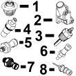
RE187966、RE205726、RE507264、RE504836、RE509036、RE533910、RE532952、RE530107、RE508971、RE523502、RE518520、RE68345、RE53307、RE62240、RE533095、RE502513、RE38009、R30402、RE62240、P524837、RE60021、RE507236、RE59588、RE549153、RE530870、SE501610、SE501609、RE70960rg,rg34710,258 –19–26oct00–1/1 replace final (secondary) fuel filter element rg8720 –un–05dec97 removing final fuel filter rg8721 –un–05dec97 installing final fuel filter a—fuel filter wrench b—filter gasket/o-ring remove final fuel filter 1. close fuel shut-off valve at bottom of fuel tank (not illustrated). 2. clean entire area surrounding fuel filter assembly to keep debris from entering fuel system. 3. remove final fuel filter using a suitable filter wrench (a). dispose of fuel&filter in an environmentally safe manner. install new final fuel filter 1. if removed, install fuel filter mounting bracket and tighten cap screws to the following specifications. specification fuel filter header-to-bracket— torque . 50 n?m (37 lb-ft) fuel filter bracket-to-head— torque . 35 n?m (26 lb-ft) fuel filter bracket-to-block— torque . 65 n?m (48 lb-ft) fuel filter-to-air intake—torque. 25 n?m (18 lb-ft) 2. clean filter gasket sealing surface with a clean, lint-free towel. 3. apply a light coating of clean engine oil to filter gasket/o-ring (b). 4. fill filter element with clean diesel fuel. 5. install filter element onto threaded adapter&tighten until gasket contacts sealing surface on mounting base. then, tighten an additional 3/4 turn. 6. open fuel shut-off valve&bleed the fuel system. see bleed fuel system later in this group. ctm188 (20mar01) 02-090-3 powertech 10.5 l & 12.5 l level 6 fuel system 032001 pn=33 dual rail fuel system repair&adjustment 02 090 4 rg,rg34710,259 –19–03aug99–1/2 replacing primary fuel filter/water separator rg8722 –un–05dec97 removing primary fuel filter a—filter wrench b—clear water separator bowl remove primary fuel filter/water separator 1. close fuel shut-off valve at bottom of fuel tank (not illustrated). 2. clean entire area surrounding fuel filter assembly to keep debris from entering fuel system. 3. remove primary fuel filter using a suitable filter wrench (a). drain filter element&sediment bowl into appropriate container. 4. clamp filter element in a vise&remove clear water separator bowl (b). 5. thoroughly clean sediment bowl&dry with compressed air. continued on next page ctm188 (20mar01) 02-090-4 powertech 10.5 l & 12.5 l level 6 fuel system 032001 pn=34 dual rail fuel system repair&adjustment 02 090 5 rg,rg34710,259 –19–03aug99–2/2 rg8723 –un–05dec97 installing primary fuel filter a—filter gasket/o-ring install primary fuel filter/water separator 1. if removed, install fuel filter mounting bracket and tighten cap screws to the following specifications. specification fuel filter bracket-to-head— torque . 35 n?m (26 lb-ft) fuel filter bracket-to-block— torque . 65 n?m (48 lb-ft) primary fuel filter header-to-bracket—torque 50 n?m (37 lb-ft) 2. lubricate sediment bowl o-ring with clean engine oil and install onto new filter element. tighten bowl an additional 1/2 turn after o-ring contacts filter element. 3. apply a light coating of engine oil to filter gasket/o-ring (a). 4. close sediment bowl drain adapter&fill filter element with clean diesel fuel. 5. install filter element onto threaded adapter&tighten until gasket contacts sealing surface on mounting base. then, tighten an additional 1-1/2 turn. 6. install any plugs removed from filter header&tighten to specifications. specification primary fuel filter header plugs—torque. 47 n?m (35 lb-ft) 7. open fuel shut-off valve&bleed the fuel system. see bleed fuel system in this group. ctm188 (20mar01) 02-090-5 powertech 10.5 l & 12.5 l level 6 fuel system 032001 pn=35 dual rail fuel system repair&adjustment 02 090 6 dpsg,ouo1004,975 –19–03aug99–1/1 remove&install air purge valve rg9625 –un–04dec98 in-line purge valve rg10276 –un–11aug99 header mounted purge valve a—purge valve b—filter outlet line c—cap d—elbow e—diagnostic port fitting note: purge valves are located on outlet side of fuel filter. 1. disconnect fuel line (b)/remove elbow (d) as required. 2. remove air purge valve. 3. install air purge valve. tighten line (b) to specifications. specification fuel line-to-fuel filter/air purge valve—torque. 24 n?m (18 lb-ft) 4. install elbow (d)&diagnostic port fitting (e) if removed. tighten diagnostic fitting to specifications. specification air purge valve diagnostic port fitting—torque 24 n?m (18 lb-ft) 5. install cap (c). ctm188 (20mar01) 02-090-6 powertech 10.5 l & 12.5 l level 6 fuel system 032001 pn=36 dual rail fuel system repair&adjustment 02 090 7 dpsg,ouo1004,976 –19–03aug99–1/1 remove&install primary fuel filter check valve rg10277 –un–11aug99 fuel filter check valve a—fuel filter outlet line b—check valve c—elbow note: fuel filter check valve is located in an outlet port on the fuel filter header. depending on engine application, it may be located on left/right-hand side of header. additionally, check valve may connect directly to header port/to elbow (c). 1. disconnect fuel line (a)&remove check valve (b). remove o-rings from both ends of check valve. 2. apply loctite? 242 thread lock&sealer to threads on check valve&install valve on elbow (c) or header. tighten valve to specifications. specification fuel filter check valve to fuel filter header/elbow on header—torque 46 n?m (34 lb-ft) 3. if elbow (c) was removed, apply loctite? 242 thread lock&sealer to threads of elbow&install in fuel filter header. tighten elbow lock nut to specifications. specification elbow, fuel filter check valve-to-filter header—torque 46 n?m (34 lb-ft) 4. connect fuel line (a)&tighten to specifications. specification fuel line-to-fuel filter check valve—torque. 24 n?m (18 lb-ft) loctite is a registered trademark of loctite corp. ctm188 (20mar01) 02-090-7 powertech 10.5 l & 12.5 l level 6 fuel system 032001 pn=37 dual rail fuel system repair&adjustment 02 090 8 dpsg,ouo1004,1007 –19–26oct00–1/1 remove&install fuel system surge tank (6125adw01/70 engines) rg10292 –un–09sep99 surge tank a—surge tank b—mounting bracket c—line adapter (fuel tank return line) d—label (marked “top”) e—fuel line (surge tank-to-fuel manifold) f—line adapter (fuel manifold line) 1. disconnect fuel line from adapter (c) (shown disconnected). 2. disconnect fuel line (e). cap&plug all lines&fittings to prevent fuel system contamination. 3. remove surge tank (a) from mounting bracket (b). 4. if fuel line adapters (c)&(f) are removed, install new o-rings in adapters&install adapters in surge tank. tighten adapters to the following specifications. specification surge tank fuel line adapter (top)—torque . 46 n?m (34 lb-ft) surge tank fuel line adapter (bottom)—torque 39 n?m (29 lb-ft) 5. if removed, install mounting bracket (b)&tighten cap screws to specifications. specification surge tank mounting bracket-to-cylinder head cap screws—torque 130 n?m (95 lb-ft) 6. install surge tank on mounting bracket with end labeled “top” (d) in the up position as shown. center cap screws in surge tank slots&tighten to specifications. specification surge tank-to-mounting bracket cap screws—torque 50 n?m (37 lb-ft) 7. connect fuel lines&tighten to specifications. specification surge tank fuel lines—torque. 24 n?m (18 lb-ft) ctm188 (20mar01) 02-090-8 powertech 10.5 l & 12.5 l level 6 fuel system 032001 pn=38 dual rail fuel system repair&adjustment 02 090 9 rg,rg34710,260 –19–04aug99–1/2 remove&install dual rail fuel supply pump rg8566a –un–05dec97 fuel supply pump rg8777 –un–05dec97 fuel supply pump exploded view a—fuel supply pump b—mounting bracket c—tee fitting d—straight fitting important: plug/cap all fuel system connections&passages as lines or components are removed to keep debris out using jdg998 fuel system cap plug kit. remove fuel manifold note: label fuel lines as they are disconnected to ensure correct reassembly. 1. remove three fuel lines connected to fuel supply pump (a). cap all lines&fittings to keep debris out of fuel system. 2. remove four cap screws securing supply pump to mounting bracket (b)&remove pump. remove and discard o-, ring. note: fuel supply pump is not serviceable; replace pump if determined to be defective. 3. remove tee fitting (c)&straight fitting (d) from pump&clean thoroughly if pump is to be replaced. install fuel supply pump 1. install tee fitting&straight fitting onto new pump (using new o-rings) in same orientation as on original pump. tighten fittings securely. 2. ensure that drive coupler set screw is tightened to specifications on supply pump drive shaft with end of shaft flush with coupler id. check drive coupler on金昌约翰迪尔发动机进排气门座圈厂家价格,广元约翰迪尔4045柴油机输油泵多少钱,双鸭山强鹿滤芯滤清器RE42042厂家供应,赣州美国强鹿Johndeere连杆瓦RE65908代理商,曲靖约翰迪尔曲轴RE515785诚信推荐,乌兰察布约翰迪尔机油冷却器RE56690厂家价格,资阳强鹿柴油机气门挺杆哪家买,秦皇岛JohnDeere排气门TR90692代理商,潮州强鹿柴油机温度传感器RE522823信息,邯郸约翰迪尔进气门R97490厂家供货,上饶强鹿柴油机四配套DZ10211供货商,宜春强鹿消防柴油机配件批发商,平凉约翰迪尔6068柴油机水泵代理,绥化强鹿柴油发动机3029气门室盖垫片一级代理,甘南约翰迪尔气门油封RE519115供货商,菏泽约翰迪尔装载机发动机气缸垫批发价,那曲约翰迪尔9420R拖拉机发动机配件公司,汕尾强鹿Johndeere风扇总成哪家买,黔南约翰迪尔柴油发电机组缸盖诚信推荐,汕头约翰迪尔E130挖掘机柴油发动机配件代理商,中卫强鹿缸套R530609哪家好,安康强鹿6090柴油发动机凸轮轴铜衬套一级代理,甘南强鹿柴油机发动机修理包RE527549代理商,雅安约翰迪尔强鹿3029燃油输送泵哪家好,湘西强鹿柴油机水泵RE500734厂家供应,玉树强鹿柴油发动机节恒温器批发价,鄂尔多斯强鹿机滤RE58935厂家价格,乌海约翰迪尔曲轴齿轮R114282供应商,嘉峪关强鹿喷油器RE543935批发价,贺州强鹿传感器RE52722供货商,西宁约翰迪尔四配套IK526727诚信推荐,南宁强鹿滤芯滤清器RE160384供应商,迪庆强鹿6068柴油机主轴瓦哪家好,楚雄强鹿柴油机R116516气缸垫代理商,阿坝强鹿水泵O型圈TRE509463厂家供货,黔西南强鹿排气门R93313的价格,迪庆强鹿凸轮随动件R123565厂家供应,达州强鹿约翰迪尔TR97492排气门诚信推荐,泉州JohnDeereRE61767机油冷却器多少钱,苏州强鹿柴油机止推瓦RE65168价格,铁岭约翰迪尔强鹿4045柴油机曲轴齿轮代理商,运城强鹿6081柴油机气门锁夹价格行情,白山强鹿发电机RE504836滤芯滤清器厂家批发,果洛强鹿R106957凸轮轴厂家价格,陇南JohnDeere连杆铜套R74008厂家供应,台南johndeere约翰迪尔强鹿柴油发动机水泵总成RE521503厂家价格,济宁连杆螺丝强鹿4045柴油机厂家价格,金华约翰迪尔6090柴油机加大止推轴承瓦哪家买,临沧强鹿排气门导管R119132诚信推荐,鹤岗约翰迪尔强鹿曲轴齿环R28811找哪家,高雄强鹿气门锁夹T20077一级代理,漳州约翰迪尔1654拖拉机发动机配件公司,咸阳johndeere活塞环价格价格,晋中johndeere主轴瓦厂家批发,潮州美国JohnDeere启动马达RE515843供应商,黄南约翰迪尔发动机启动马达批发商,运城JOHNDEERE强鹿6081HF001配件厂家价格,七台河强鹿滤芯滤清器RE53729哪家好,贵港JohnDeere柴油机缸套R530609哪家好,海口约翰迪尔6081发动机水泵O型圈的价格,株洲美国JohnDeere水泵总成RE505980/RE505981多少钱,温州约翰迪尔R97341机油底壳垫片厂家价格,宜昌JohnDeere气门弹簧价格行情,忻州约翰迪尔装载机发动机活塞环多少钱,惠州约翰迪尔强鹿4045柴油机水泵盖公司,厦门约翰迪尔RE506428滤芯信息,三亚约翰迪尔拖拉机发动机曲轴哪家买,泉州美国强鹿RE60021柴油滤芯哪里买,荆州约翰迪尔6090柴油机凸轮轴铜衬套哪里买,鹤壁约翰迪尔发动机配件店批发,阳江强鹿R97341机油底壳垫片价格,营口强鹿柴油机活塞销R123177厂家价格,海南强鹿柴油机启动马达RE523502厂家价格, camshaft drive pin also; adjust as needed. specification fuel supply pump and camshaft drive coupler set screws—torque . 4 n?m (3 lb-ft) 3. position new rubber spider (vibration ab***ber) on drive coupler. position new o-ring on face of supply pump. 4. if removed, apply ar54749 soap lubricant to new o-ring on supply pump mounting bracket (b) and install. tighten mounting bracket cap, screws to specifications. ctm188 (20mar01) 02-090-9 powertech 10.5 l & 12.5 l level 6 fuel system 032001 pn=39 continued on next page dual rail fuel system repair&adjustment 02 090 10 rg,rg34710,260 –19–04aug99–2/2 specification fuel supply pump mounting bracket cap screws—torque 50 n?m (37 lb-ft) 5. install fuel supply pump with rubber spider properly meshed with coupler on rear of camshaft. 6. install four cap screws&tighten to specifications. specification fuel supply pump-to-bracket— torque. 25 n?m (18 lb-ft) important: before connecting orfs fuel line fittings, be sure o-ring is correctly positioned in the groove of fitting. tighten fitting only to specified torque. do not overtighten. 7. install three fuel lines&tighten to specifications. specification fuel line orfs fittings— torque. 24 n?m (18 lb-ft) ctm188 (20mar01) 02-090-10 powertech 10.5 l & 12.5 l level 6 fuel system 032001 pn=40 dual rail fuel system repair&adjustment 02 090 11 rg,rg34710,261 –19–13aug99–1/2 remove&install dual rail fuel manifold rg8566b –un–05dec97 fuel manifold rg10240 –un–05nov99 fuel manifold exploded view a—fuel manifold b—o-ring c—check valve d—not used e—temperature sen*** f—pressure regulating valve g—spring h—o-ring i—fitting j—screen1 k—plug important: plug/cap all fuel system connections and fuel rail passages as lines or components are removed to keep debris out using jdg998 fuel system cap plug kit. remove fuel manifold 1. disconnect wiring lead from fuel temperature sen*** (e). 2. remove three fuel lines from fuel manifold (a). cap all lines&fittings to keep debris out of fuel system. important: plug fuel rails with clean plugs from jdg998 fuel system cap plug kit to keep dirt&debris out even if rail is to be open for a short period of time. 3. remove two cap screws securing fuel manifold to cylinder head&remove manifold. remove o-ring (b) and discard. install fuel manifold 1. install fuel manifold using new o-ring. tighten cap screws to specifications. specification dual rail fuel manifold-to-head—torque 35 n?m (26 lb-ft) important: before connecting orfs fuel line fittings, be sure o-ring is correctly positioned in the groove of fitting. tighten fitting only to specified torque. do not overtighten. 2. install fuel lines with o-rings&tighten to specifications. specification fuel lines-to-fuel manifold— torque . 24 n?m (18 lb-ft) 1on earlier engines, screen was located in end of check valve (c). ctm188 (20mar01) 02-090-11 powertech 10.5 l & 12.5 l level 6 fuel system 032001 pn=41 continued on next page dual rail fuel system repair&adjustment 02 090 rg,rg34710,261 –19–13aug99–2/2 3. install fuel temperature sen*** wiring lead. 12 ctm188 (20mar01) 02-090-12 powertech 10.5 l & 12.5 l level 6 fuel system 032001 pn=42 dual rail fuel system repair&adjustment 02 090 13 dpsg,ouo1004,1023 –19–08sep99–1/2 inspect fuel pressure regulating valve and return check valve rg10348 –un–14sep99 pressure regulating valve rg10347 –un–14sep99 check valve with screen rg10346 –un–14sep99 fuel screen&check valve a—fitting b—spring c—pressure regulating valve d—screen (early engines) e—screen (later engines) f—check valve 1. carefully remove parts (a—c). do not drop pressure regulating valve (c). important: the pressure regulating valve (c) should come out with the spring. if the valve is stuck in the fuel manifold, replace the fuel manifold&flush the fuel rail. see remove&install dual rail fuel manifold earlier in this group. see flush fuel rails later in this group. 2. inspect the pressure regulating valve for debris. if debris is found, clean valve assembly&flush the fuel rail. see flush fuel rails later in this group. 3. remove fuel return check valve from manifold block. 4. inspect screen (d) in end of check valve/remove plug&screen (e) from manifold block&check for debris. clean screen as required. 5. reinstall parts in reverse order of removal. hand tighten return check valve. 6. whenever the fuel manifold is serviced, air must be removed from the fuel galley. loosen return check valve (f)&operate hand primer on fuel filter until air is removed&fuel is leaking past the o-ring. tighten check valve to specifications. specification fuel return check valve (on manifold)—torque. 33 n?m (24 lb-ft) ctm188 (20mar01) 02-090-13 powertech 10.5 l & 12.5 l level 6 fuel system 032001 pn=43 continued on next page dual rail fuel system repair&adjustment 02 090 dpsg,ouo1004,1023 –19–08sep99–2/2 7. bleed fuel system. see bleed fuel system later in this group. 14 rg,rg34710,262 –19–04aug99–1/5 remove&install electronic unit injectors rg8279 –un–05dec97 unit injector clamp screws a—clamp cap screws important: electronic unit injectors on dual rail fuel systems are different from injectors on single rail systems. use the appropriate injector for engine/fuel system applications. replace injector with the same type removed. do not intermix injectors. 1. remove rocker arm cover. see remove and install rocker arm cover in ctm100, section 02, group 020. 2. remove rocker arm shaft assembly. see remove rocker arm assembly in ctm100, section 02, group 020. 3. disconnect fuel lines&drain fuel from lines&fuel rail in cylinder head. 4. reconnect lines (or install cap plugs from jdg998 fuel system cap plug kit) to keep debris out of fuel system. 5. remove injector hold-down clamp cap screws (a). continued on next page ctm188 (20mar01) 02-090-14 powertech 10.5 l & 12.5 l level 6 fuel system 032001 pn=44 dual rail fuel system repair&adjustment 02 090 15 rg,rg34710,262 –19–04aug99–2/5 rg8280 –un–05dec97 position prybar rg8281 –un–05dec97 removing unit injector rg8551b –un–05dec97 unit injector removed a—hold-down clamp b—prybar c—injector o-rings 6. pry upward on the injector hold-down clamp (a) against cylinder head using a prybar (b) as shown. 7. remove injector&clamp from cylinder head. label injector for installation in same cylinder location as removed. 8. immediately plug injector bore with clean cap plug to keep debris out of fuel system. 9. remove injector o-rings (c)&discard. 10. store injector in a clean, lint-free container. continued on next page ctm188 (20mar01) 02-090-15 powertech 10.5 l & 12.5 l level 6 fuel system 032001 pn=45 dual rail fuel system repair&adjustment 02 090 16 rg,rg34710,262 –19–04aug99–3/5 rg8551a –un–05dec97 installing unit injector a—o-rings install electronic unit injectors 1. remove cap plug from injector bore in cylinder head. clean entire sleeve using a clean, lint-free cloth wrapped around a wooden stick. 2. install two new o-rings (a) on unit injector body. lubricate o-rings with clean engine oil/amojell lubricant. continued on next page ctm188 (20mar01) 02-090-16 powertech 10.5 l & 12.5 l level 6 fuel system 032001 pn=46 dual rail fuel system repair&adjustment 02 090 17 rg,rg34710,262 –19–04aug99–4/5 rg10249 –un–30jul99 injector hold-down clamp screws rg9574 –un–04dec98 torque-turn eui a—clamp cap screw b—ratchet handle important: press on top of injector plunger with palm of hand to properly seat o-rings and center injector between valve springs. note: new eui hold-down clamp cap screws have pre-applied sealant. 3. install unit injector with hold-down clamp into same cylinder as removed (solenoid outward toward exhaust manifold side of engine at equal distance between exhaust valve springs). apply loctite? 242 thread lock&sealer to used hold-down cap screw. initially tighten cap screw to specifications. specification electronic unit injector hold-down clamp cap screws— initial torque 20 n?m (15 lb-ft) 4. mark head of cap screw at twelve o’clock position (a) (viewed from rear) using a paint stick. 5. install 13 mm swivel socket on head of cap screw. position ratchet handle (b) parallel with centerline of engine camshaft/crankshaft. torque-turn cap screw to the following specification. specification electronic unit injector hold-down clamp cap screws— final torque-turn 90—100° 6. remove socket from head of cap screw&verify that mark has been tightened/turned at least 90° but not more than 100° from its original position. loctite is a registered trademark of loctite corp. continued on next page ctm188 (20mar01) 02-090-17 powertech 10.5 l & 12.5 l level 6 fuel system 032001 pn=47 dual rail fuel system repair&adjustment 02 090 18 rg,rg34710,262 –19–04aug99–5/5 rg8263 –un–05dec97 wiring terminal nuts b—retaining nuts important: do not use red/blue loctite? on solenoid studs. bonding strength is too high for small studs, making future removal impossible without twisting off stud. 7. reconnect injector solenoid wiring leads onto solenoid studs. apply loctite? 222 small screw thread locker (ty24311) to studs&tighten retaining nuts (b) to specifications. specification electronic unit injector harness connector nuts—torque 2 n?m (1.75 lb-ft) (18 lb-in.) 8. install valve bridges, push tubes,&rocker arm assembly. adjust valve stem-to-bridge clearances. see install rocker arm assembly in ctm100, section 02, group 020. 9. if removed/loosened, tighten all harness&line clamps to specifications. specification fuel line clamps—torque . 5 n?m (4 lb-ft) electronic unit injector harness-to-shaft clamps— torque . 35 n?m (26 lb-ft) electronic unit injector wiring connector bracket-to-head— torque . 25 n?m (18 lb-ft) 10. adjust electronic unit injector preload as detailed later in this group. loctite is a registered trademark of loctite corp. ctm188 (20mar01) 02-090-18 powertech 10.5 l & 12.5 l level 6 fuel system 032001 pn=48 dual rail fuel system repair&adjustment 02 090 19 rg,rg34710,263 –19–03nov00–1/3 adjust electronic unit injector preload rg8228a –un–05dec97 jdg971 timing pin in camshaft rg8227d –un–05dec97 jdg971 timing pin in crankshaft rg11165 –un–30oct00 camshaft timing slot a—jdg971 timing pin b—jdg820 flywheel turning tool c—jdg971 timing pin d—single timing slot e—double timing slot 1. remove plug from cylinder block&install jdg820 flywheel turning tool (b). important: timing pin must be installed in slot of camshaft first. then install second timing pin in crankshaft slot by carefully rocking flywheel back and forth. 2. rotate engine flywheel in running direction (counterclockwise as viewed from rear) until jdg971 timing pin (a) engages single timing slot (d) in camshaft. the proper timing slot can be found by viewing camshaft timing lobe through camshaft timing pin bore while rotating engine. the double timing slot (e) will be at approximately 11 o’clock (viewed from rear of engine) when pin is installed in slot (d).this ensures that engine is locked at tdc of no. 1 cylinder’s compression stroke. intake&exhaust rocker arms on no. 1 cylinder should be loose. 3. remove threaded plug from crankshaft timing hole below oil cooler&filter housing assembly. important: do not insert timing pin full depth into cylinder block crankshaft timing hole when rotating engine flywheel until double slot on camshaft timing lobe is at approximately 11 o’clock (viewed from rear of engine) to avoid crankshaft counterweight bending timing pin. 4. slightly move engine flywheel back&forth with turning tool until a second jdg971 timing pin (c) can be installed in slot in crankshaft. this ensures that camshaft&crankshaft are in sync (properly timed). ctm188 (20mar01) 02-090-19 powertech 10.5 l & 12.5 l level 6 fuel system 032001 pn=49 continued on next page dual rail fuel system repair&adjustment 02 090 20 rg,rg34710,263 –19–03nov00–2/3 if timing pin does not enter crankshaft timing slot, crankshaft is not properly timed with camshaft. crankshaft must be timed to camshaft. see check and adjust camshaft-to-crankshaft timing in ctm100, section 02, group 050. rg,rg34710,263 –19–03nov00–3/3 rg8270 –un–05dec97 unit injector adjusting screw a—lock nut b—adjusting screws 5. loosen lock nut (a)&loosen cylinders nos. 3, 5, and 6 injector rocker arm adjusting screws (b) to relieve tension. 6. slowly tighten adjusting screw until rocker arm roller contacts camshaft lobe at 0.0 clearance. 7. tighten adjusting screw an additional 1/2 turn (180°) to preload injector. tighten adjusting screw lock nut to specifications while holding adjusting screw stationary. specification electronic unit injector adjusting screw lock nut—torque 65 n?m (48 lb-ft) 8. remove both timing lock pins, rotate crankshaft one full revolution (360°)&pin crankshaft only. engine will now be locked at no. 6 tdc. 9. set injector preload on cylinders nos. 1, 2,&4. 10. install plug in timing pin hole in block&tighten to specifications. specification timing pin plug in cylinder block—torque. 33 n?m (24 lb-ft) ctm188 (20mar01) 02-090-20 powertech 10.5 l & 12.5 l level 6 fuel system 032001 pn=50 dual rail fuel system repair&adjustment 02 090 21 rg,rg34710,264 –19–20nov00–1/1 replace electronic unit injector o-rings rg8567 –un–05dec97 unit injector&clamp a—o-rings 1. the electronic unit injector’s two external o-rings (a) must be replaced whenever injector is removed. 2. fuel system diagnosis will determine if unit injector is not functioning properly. refer to section 04, groups 150&160, as required. 3. replaced unit injectors will be returned by your authorized servicing dealer to the manufacturer for testing&rebuilding. dpsg,ouo1004,1027 –19–15sep99–1/1 replace electronic unit injector thrust sleeve, pad&o-ring rg10352 –un–16sep99 electronic unit injector a—thrust socket b—o-ring c—thrust pad 1. using an o-ring pick, remove o-ring (b). 2. remove thrust socket (a)&pad (c). 3. coat parts with clean engine oil&install in reverse order. ctm188 (20mar01) 02-090-21 powertech 10.5 l & 12.5 l level 6 fuel system 032001 pn=51 dual rail fuel system repair&adjustment 02 090 22 dpsg,ouo1004,1024 –19–08sep99–1/2 flush fuel rails rg10345 –un–14sep99 flush fuel rail (dual rail fuel system) a—primary filter inlet check f—return-to-tank check j—recirculation fuel line m—pressure regulating valve valve valve (low pressure) n—spring b—hand primer pump g—return-to-tank fuel line k—fuel inlet line-to-fuel o—fitting c—primary filter (low pressure) manifold (high pressure) d—final filter h—fuel manifold l—primary filter e—transfer pump-to-final i—fuel supply pump outlet-to-supply pump inlet filter (high pressure) (low pressure) whenever the fuel system is opened for major service, flush the fuel rails in cylinder head. 1. disconnect recirculation fuel line (j) from pressure regulating valve&remove parts (m—o). reinstall fitting (o)&connect fuel line, leaving spring (n) and valve (m) out. 2. disconnect recirculation line (j) from fuel supply pump inlet fitting&install cap on inlet fitting. attach the clear line from jt03513 fuel supply system test kit to the end of the recirculation line and place end in a ***et/route to fuel tank. 3. operate hand primer pump (b) until clear fuel flows out of the recirculating line into the ***et/fuel tank. 4. pinch off the recirculation line (not the plastic line from test kit) from the fuel manifold to the ***et just long enough to start the engine. when engine starts, release line&allow fuel to flow into ***et/fuel tank. run engine for five minutes. 5. stop engine. 6. disconnect fuel line&remove fitting (o). install valve (m), spring (n)&fitting (o). connect fuel line. 7. remove cap from fuel supply pump inlet fitting and remove clear test line from recirculation line. connect recirculation line to pump inlet fitting. 8. tighten fuel lines to specifications. specification fuel line orfs fittings— torque. 24 n?m (18 lb-ft) ctm188 (20mar01) 02-090-22 powertech 10.5 l & 12.5 l level 6 fuel system 032001 pn=52 continued on next page dual rail fuel system repair&adjustment 02 090 23 dpsg,ouo1004,1024 –19–08sep99–2/2 9. whenever the fuel manifold is opened, air must be removed from the fuel galley. loosen return check valve (f)&operate hand primer on fuel filter until air is removed&fuel is leaking past the o-ring. tighten check valve to specifications. specification fuel return check valve (on manifold)—torque 33 n?m (24 lb-ft) rg,rg34710,265 –19–04aug99–1/1 bleed fuel system rg8714a –un–05dec97 draining water separator rg8725 –un–05dec97 bleeding fuel system rg10250 –un–30jul99 air purge valve a—fuel filter outlet line b—hand primer c—clear water separator sediment bowl d—air purge valve e—cap whenever the fuel system has been opened up for service (lines disconnected/filters removed), it will be necessary to bleed air from the system. 1. drain water&contaminants from clear water separator sediment bowl (c) by opening drain valve and operating primer until bowl is clear of water and debris. 2. loosen secondary (final) fuel filter outlet line (a) or remove cap (e)&open air purge valve (d), (if equipped). 3. pump hand primer (b) on primary filter until a steady flow of fuel (without bubbles) comes out of connection. 4. continue pumping hand primer&simultaneously close purge valve/tighten outlet line connection to specifications. do not overtighten. specification fuel filter outlet line—torque. 24 n?m (18 lb-ft) 5. start engine&run at high idle for 5—10 minutes. ctm188 (20mar01) 02-090-23 powertech 10.5 l & 12.5 l level 6 fuel system 032001 pn=53 dual rail fuel system repair&adjustment 02 090 24 ctm188 (20mar01) 02-090-24 powertech 10.5 l & 12.5 l level 6 fuel system 032001 pn=54 group 091 single rail fuel system repair&adjustment 02 091 1 dpsg,ouo1004,1125 –19–20oct99–1/1 general information later 10.5 l engines s.n. (003764 — )&12.5 l engines s.n. (010967 — ) have the single rail fuel system covered in this group. earlier engines have the dual rail fuel system covered in group 090. important: always use a new (dry) fuel filter element whenever an existing element is removed from the filter housing. reusing a wet element may cause fuel to overflow from the filter housing during insertion of filter element. also, trapped air in the core of a wet filter element may cause the engine to stall and not restart without additional system purging. ctm188 (20mar01) 02-091-1 powertech 10.5 l & 12.5 l level 6 fuel system 032001 pn=55 single rail fuel system repair&adjustment 02 091 2 dpsg,ouo1004,996 –19–26oct00–1/2 single rail fuel system components (later engines) rg10287 –un–26aug99 single rail fuel system components (later engines) a—fuel supply pump c—cylinder head g—check valve k—pre-filter (optional) b—electronic unit injector d—fuel rail h—water drain l—fuel primer (eui) (6 used) e—fuel pressure sen*** i—water in fuel sen*** m—fuel temperature sen***2 f—return line to fuel tank1 j—inlet line from fuel tank n—diagnostic test port the single rail fuel system is used on later engines: 10.5 l engines s.n. (003764— )&12.5 l engines (010967— ). note: fuel flow through cylinder head may vary by engine application. supply pump (a) may be mounted as shown with fuel entering the front left side of the cylinder head&exiting the back of the head. on some machine applications, the fuel supply pump is rotated 180°&the fuel lines on cylinder head are reversed, with fuel entering the back of the head&exiting the front left side of the head. 6125adw engines&6125hf(af) shown above. 6015hrw&6125hrw engines have fuel system components located on left side of engine as viewed from flywheel end. service procedures are same for both engines. 1low pressure regulating valve is inside this 新疆强鹿柴油发动机曲轴哪里买,淮南johndeere约翰迪尔强鹿柴油发动机RE506197批发商,聊城美国约翰.迪尔(强鹿)JOHNDEERE纯正配件价格,海南约翰迪尔柴油发电机组柴油泵供货商,平凉强鹿柴油机传感器RE519144代理商,哈尔滨JohnDeere节温器RE522076多少钱,惠州强鹿RE55900凸轮轴哪家好,伊春约翰迪尔燃油输油泵RE68345的价格,泰州强鹿柴油机止推轴承RE65168价格行情,filter housing bore. 2high pressure regulating valve&filter screen is inside this filter housing bore behind temperature sen***. ctm188 (20mar01) 02-091-2 powertech 10.5 l & 12.5 l level 6 fuel system 032001 pn=56 continued on next page single rail fuel system repair&adjustment 02 091 3 dpsg,ouo1004,996 –19–26oct00–2/2 important: during engine repair, cleanliness of the fuel supply rail (d) in cylinder head (c) is extremely important due to fuel flow through passage. think of the fuel rails as internal passages of an injection pump; therefore, same cleanliness must be maintained when disconnecting inlet and outlet lines to fuel supply rail. KEY PART NO. PART NAME QTY SERIAL NO. F F F REMARKS
1 R67364 ELBOW FITTING 2 X
2 R51936 SEALING WASHER 6 X
3 RE66060 FUEL LINE 1 X (B) (SUB FOR RE63665)
4 R135106 CLAMP 1 X (SUB FOR R70407)
5 R67271 UNION FITTING 1 X
6 19H1731 CAP SCREW 1 X 3/8" X 1"
, 7 12H304 LOCK WASHER 1 X 3/8"
8 RE503559 FUEL LINE 1 X (SUB FOR RE63664)
9 28H1518 WASHER 1 X 0.493" X 0.675" X 5/16"
10 RE49589 FUEL LINE 1 -087549 X
RE501218 FUEL LINE 1 087550-090585 X (SUB RE504748)
RE504748 FUEL LINE 1 090586- X
11 R76358 O-RING 1 X
12 R121195 CAP SCREW 4 X
13 R121164 GEAR 1 X (SUB FOR R112975, THIS APPLICATION)
14 R67364 ELBOW FITTING 1 -087549 X
RE502650 FITTING 1 087550- X
15 R114130 STUD 4 X (SUB FOR R55396, THIS APPLICATION)
16 M72490 WASHER 4 X
17 14H1090 NUT 4 X 3/8", (SUB FOR E55662, THIS
APPLICATION)
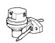
18 RE46252 FUEL PUMP 1 X (ROBERT BOSCH)
19 R67264 PACKING 2 X
20 AR87561 OIL LINE 1 X
21 AR88903 ELBOW FITTING 1 X
22 R79060 O-RING 1 X
23 RE66244 FUEL INJECTION PUMP 1 X (A) (ROBERT BOSCH) (ALSO ORDER R112128
AND (2) 19M8826)
24 R51936 SEALING WASHER 2 X
25 RE44030 OIL LINE 1 X
26 RE502650 FITTING 1 X (SUB FOR R63604)
27 AR87636 TEE FITTING 1 X
.. R83490 FITTING 1 X
(A) "SEE YOUR AUTHORIZED PUMP REPAIR STATION FOR PARTS NOT LISTED"
CONSULTEZ VOTRE REPARATEUR DE POMPE AGREE POUR LES PIECES NON CATALOGUES
NICHT GEZEIGTE TEILE VON PUMPENWERKSTAT BEZIEHEN.
PER LE PARTI NON ELENCATE, RIVOLGETEVI AL CENTRO AUTORIZZATO DI RIPARAZIONE POMPA
CONSULTE CON SU ESTACION AUTORIZADA RE PEPARACIONES DE BOMBA.
RAADGOER MED EN AUTORISERAD PUMPSERVICVERKSTAD BETRAEFFANDE EJ UPPTAGNA
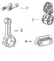
KEY PART NO. PART NAME QTY SERIAL NO. F F F REMARKS
1 21H1319 SCREW 1 X 0.164" X 7/8"
2 12H315 LOCK WASHER 1 X 0.164"
3 24H1136 WASHER 2 X 11/32" X 11/16" X 0.065"
4 19H1900 CAP SCREW 2 X 5/16" X 3/4"
5 R99930 BRACKET 1 X (A)
6 R104675 CLIP 1 X
7 14H605 NUT 1 X 0.164"
8 R104592 PIPE PLUG 1 X
9 R128694 BASE 1 X (SUB FOR R127415) (ALSO ORDER (2)
R104592)
(A) SHUT-OFF
ROBINET D’ARRET
ABSCHALTUNG
RUBINETTO D’ARRESTO
GRIFO DECIERRE
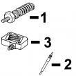
AVSTAENGINGKEY PART NO. PART NAME QTY OR PUMP DATE F F F REMARKS
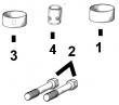
1 R63059 SPRING 1 X
2 R63060 PISTON 1 X
3 R67886 O-RING 1 X
4 R67885 HOUSING 1 X
5 R63063 SCREW 2 X
6 R54880 LOCK WASHER 2 X
7 R62104 VALVE 1 X
8 R62105 PIN FASTENER 1 X
9 R26373 SPRING 1 X
10 R62107 WASHER 2 X
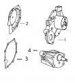
11 R62106 SCREW 1 XKE, Y PART NO. PART NAME QTY SERIAL NO. F F F REMARKS
1 .. HOLDER NA, X
2 T24210 O-RING 6 X
3 R76358 O-RING 1 X
4 14M7272 NUT 3 X M6
5 12M7006 LOCK WASHER 3 X 0.236"
6 R67879 GASKET 1 X
7 R53899 WASHER 1 X
8 AR77114 CONTROL VALVE 1 X
9 R53901 WASHER 1 X
10 R63016 ADAPTER 1 X
11 R67364 ELBOW FITTING 1 -087549 X
RE502650 FITTING 1 087550- X