珀金斯403F-15T、404F-22、404F-22T维修技术参数供应商,珀金斯403F-15T、404F-22、404F-22T维修技术参数技术价格规格咨询服务,珀金斯403F-15T、404F-22、404F-22T维修技术参数零配件供应,珀金斯403F-15T、404F-22、404F-22T维修技术参数售后服务中心,珀金斯403F-15T、404F-22、404F-22T维修技术参数,珀金斯403F-15T、404F-22、404F-22T维修技术参数详细的技术参数,

珀金斯403F-15T、404F-22、404F-22T维修技术参数一(英文)
详细描述
Specifications
403F-15T, 404F-22 and 404F-22T
Industrial Engines
EL (Engine)
EN (Engine)
EP (Engine)
This document is printed from SPI². Not for RESALE
![]()
![]()
![]()
![]()

Important Safety Information
Most accidents tha t involve produc t op eration, ma intena nc e and repair are caus ed by failure to
ob serve basic safety rules or precautions . An accident can often be avoided by recog nizing pote ntially
ha za rdous situations before an accident oc curs . A person mus t be alert to pote ntial ha za rds. This
person should also ha ve the ne cessary training, skills and tools to perform the se func tions properly.
Improper operation, lubrication, maintenance or repair of this product can be dangerous and
could result in injury or death.
Do not operate or perform any lubrication, maintenance or repair on this product, until you have
read and understood the operation, lubrication, maintenance and repair information.
Sa fety precautions and warning s are provided in this ma nua l and on the produc t. If the se ha za rd
warning s are not he eded, bod ily injury or death could oc cur to you or to othe r persons .
The ha za rds are identified by the “Safety Alert Symb ol” and followed by a “Signa l Word” suc h as
“DANGER”, “WARNING” or “CAUTION”. The Sa fety Alert “WARNING” label is shown below.
The me aning of this safety alert symb ol is as follows:
Attention! Become Alert! Your Safety is Involved.
The me ssage tha t appears und er the warning explains the ha za rd and can be either written or
pictorially presente d.
Op erations tha t ma y caus e produc t dama ge are identified by “NOTICE” labels on the produc t and in
this pub lication.
Perkins cannot anticipate every possible circumstance that might involve a potential hazard. The
warnings in this publication and on the product are, therefore, not all inclusive. If a tool, procedure,
work method or operating technique that is not specifically recommended by Perkins is used,
you must satisfy yourself that it is safe for you and for others. You should also ensure that the
product will not be damaged or be made unsafe by the operation, lubrication, maintenance or
repair procedures that you choose.
The informa tion, specifications , and illustrations in this pub lication are on the basis of informa tion tha t
was available at the time tha t the pub lication was written. The specifications , torque s, pressure s,
me asure me nts , adjustme nts , illustrations , and othe r items can cha ng e at any time. These cha ng es can
affect the service tha t is given to the produc t. Ob tain the comp lete and mos t current informa tion before
you start any job. Pe rkins dealers or Pe rkins distributors ha ve the mos t current informa tion available.
When replacement parts are required for this
product Perkins recommends using Perkins
replacement parts.
Failure to heed this warning can lead to prema-
ture failures, product damage, personal injury or
death.
This document is printed from SPI². Not for RESALE
![]()
![]()
KENR9143
3
Table of Contents
Table of Contents
Glow Plugs .......................... ........................... 33
Index Section
SpecificationsSection
Index................................ ............................... 35
Engine Design ......................... ......................... 4
Fuel Injection Lines...................... ..................... 5
Fuel Injection Pump..................... ..................... 5
Fuel Injector........................... ........................... 6
Fuel Transfer Pump..................... ..................... 6
Lifter Group............................ ........................... 7
Rocker Shaft........................... .......................... 7
Valve Mechanism Cover.................. ................. 8
Cylinder Head Valves .................... ................... 8
Cylinder Head......................... ........................ 10
Turbocharger......................... ......................... 12
Air Pump (ARD Air)..................... .................... 12
Exhaust Cooler (NRS) (If equipped)........ ....... 13
Exhaust Manifold...................... ...................... 14
Exhaust Combustion (ARD) .............. ............. 14
Camshaft............................ ............................ 15
Engine Oil Lines....................... ....................... 17
Engine Oil Relief Valve.................. ................. 17
Engine Oil Pump....................... ...................... 18
Engine Oil Pan........................ ........................ 19
Crankcase Breather.................... .................... 20
Water Temperature Regulator ............ ............ 20
Cylinder Block......................... ........................ 21
Crankshaft........................... ........................... 21
Connecting Rod Bearing Journal.......... .......... 22
Main Bearing Journal................... ................... 23
Connecting Rod....................... ....................... 23
Piston and Rings ...................... ...................... 24
Balancer .......................................................... 25
Housing (Front)........................ ....................... 26
Gear Group (Front)..................... .................... 26
Flywheel .......................................................... 27
Flywheel Housing...................... ..................... 27
Crankshaft Pulley ...................... ..................... 28
Belt Tension Chart ..................... ..................... 29
Fan Drive............................ ............................ 29
Engine Lifting Bracket................... .................. 29
Alternator and Regulator................. ................ 30
Electric Starting Motor .................. .................. 30
Coolant Temperature Sensor............. ............. 31
Engine Oil Pressure Switch.............. .............. 31
Boost Pressure Sensor (If equipped) ...... ....... 32
Inlet Manifold Temperature Sensor......... ........ 32
Temperature Sensor (DPF Inlet)........... .......... 32
Temperature Sensor (DOC Inlet).......... .......... 33
Speed/Timing Sensor................... .................. 33
This document is printed from SPI². Not for RESALE
![]()
4
KENR9143
Specifications Section
SpecificationsSection
The front of the engine is opposite the flywheel end of
the engine. The left side and the right side of the
engine are determined from the flywheel end.
Number 1 cylinder is the front cylinder of the engine.
i05095429
Engine Design
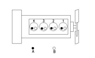
404F-22 Engine
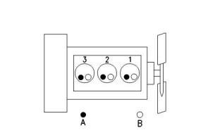
403F-15T Engine
Illustration 2
g00296424
Cylinder and valve location
(A) Exhaust valve
(B) Inlet valve
Bore .................................................. 84 mm (3.3 inch)
Stroke ............................................. 100 mm (3.9 inch)
Displacement....................................2.216 L (135 in3)
Cylinder arrangement ........................................In-line
Type of combustion ...........................Indirect injection
Compression ratio ............................................. 23.3:1
Number of cylinders .................................................. 4
Valves per cylinder .................................................... 2
Valve lash
Illustration 1
g00852304
Cylinder and valve location
(A) Exhaust valve
(B) Inlet valve
Bore ..................................................84 mm (3.3 inch)
Stroke ...............................................90 mm (3.5 inch)
Displacement......................................1.496 L (91 in3)
Cylinder arrangement ........................................In-line
Type of combustion ...........................Indirect injection
Compression ratio .............................................22.5:1
Number of cylinders .................................................. 3
Valves per cylinder .................................................... 2
Valve lash
Inlet valve............................0.2 mm (0.0078 inch)
Exhaust valve......................0.2 mm (0.0078 inch)
Firing order .....................................................1, 3, 4, 2
When the crankshaft is viewed from the front of the
engine, the crankshaft rotates in the following
direction. .....................................................Clockwise
Inlet valve............................0.2 mm (0.0078 inch)
Exhaust valve...................... 0.2 mm (0.0078 inch)
Firing order .........................................................1, 2, 3
When the camshaft is viewed from the front of the
engine, the camshaft rotates in the following direction.
.....................................................................Clockwise
When the crankshaft is viewed from the front of the
engine, the crankshaft rotates in the following
direction. .....................................................Clockwise
The front of the engine is opposite the flywheel end of
the engine. The left side and the right side of the
engine are determined from the flywheel end.
Number 1 cylinder is the front cylinder of the engine.
When the camshaft is viewed from the front of the
engine, the camshaft rotates in the following direction.
.....................................................................Clockwise
This document is printed from SPI². Not for RESALE
![]()
![]()
![]()

![]()
![]()
KENR9143
5
Specifications Section
404F-22T Engine
Illustration 3
g00296424
Cylinder and valve location
(A) Exhaust valve
(B) Inlet valve
Bore ..................................................84 mm (3.3 inch)
Stroke .............................................100 mm (3.9 inch)
Displacement....................................2.216 L (135 in3)
Cylinder arrangement ........................................In-line
Type of combustion ...........................Indirect injection
Compression ratio .............................................23.5:1
Number of cylinders .................................................. 4
Valves per cylinder .................................................... 2
Valve lash
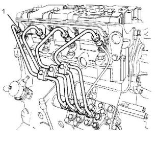
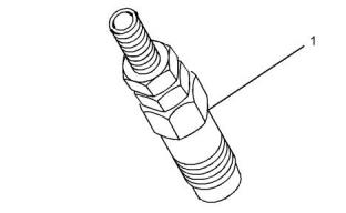
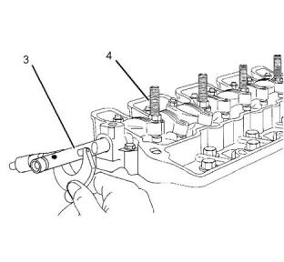
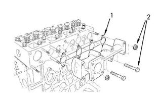
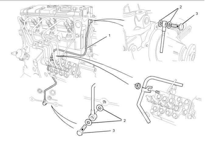
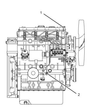
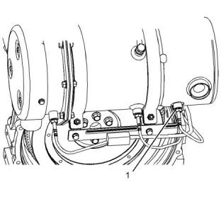
Illustration 4
g01442026
(1) Torque for the union nuts for the fuel injectors
All models.....................................20 N·m (15 lb ft)
Inlet valve............................0.2 mm (0.0078 inch)
Exhaust valve...................... 0.2 mm (0.0078 inch)
Firing order .....................................................1, 3, 4, 2
When the crankshaft is viewed from the front of the
engine, the crankshaft rotates in the following
direction. .....................................................Clockwise
When the camshaft is viewed from the front of the
engine, the camshaft rotates in the following direction.
.....................................................................Clockwise
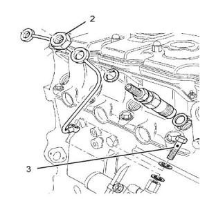
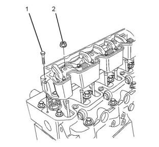
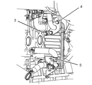
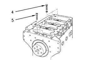
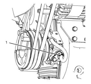
Illustration 5
g01442096
(2) Torque for the nut ..........................27 N·m (20 lb ft)
(3) Torque for the banjo bolt..............2.5 N·m (22 lb in)
The front of the engine is opposite the flywheel end of
the engine. The left side and the right side of the
engine are determined from the flywheel end.
Number 1 cylinder is the front cylinder of the engine.
Note: All washers must be replaced when the fuel
lines are removed.
i02959954
i05124091
Fuel Injection Lines
Fuel Injection Pump
This document is printed from SPI². Not for RESALE
![]()
![]()
![]()
![]()
![]()
![]()
![]()
6
KENR9143
Specifications Section
• 0.20 mm (0.008 inch)
• 0.25 mm (0.010 inch)
• 0.30 mm (0.012 inch)
• 0.35 mm (0.014 inch)
• 0.40 mm (0.016 inch)
• 0.50 mm (0.020 inch)
i05097870
Fuel Injector
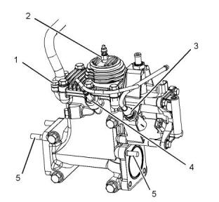
Illustration 6
g01329882
Typical example
Type of fuel injection pump .................In-line cassette
Direction of rotation of the camshaft for the fuel
injection pump ...............Clockwise from the drive end
(1) Torque for the mounting nuts and setscrews
............................................................15 N·m (11 lb ft)
(2) Torque for the delivery valve holders ..........42 N·m
(31 lb ft)
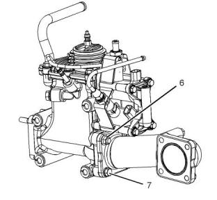
Illustration 7
g01335248
Typical example
(3) Shim
(1) Tighten the fuel injectors to the following torque.
............................................................64 N·m (47 lb ft)
The shim adjusts the timing of the fuel injection pump.
A thicker shim regresses the timing. A thinner shim
advances the timing. The timing changes 1 degree for
each 0.10 mm (0.004 inch) difference in the
thickness of the shim. More than one shim can be
used. If the fuel injection pump is reinstalled, new
shims, which have the same thickness as the original
shims, must be installed.
Note: Remove the original seat washer from the hole
for the fuel injector. Do not reuse the original seat
washer.
Note: Apply a 2 mm (0.0787 inch) bead of Loctite
638 to the first 6 mm (0.2362 inch) of the thread to
the fuel injector.
If any of the following new components are installed,
new shims which have the same thickness as the
original shims must be used.
Injector opening pressures for all models
• Camshaft
...................................................14700 kPa (2132 psi)
• Cylinder block
Leakage in 10 seconds ...................................0 drops
The following thicknesses of shims are available:
i05192446
Fuel Transfer Pump
This document is printed from SPI². Not for RESALE
![]()

![]()
![]()
![]()
![]()
KENR9143
7
Specifications Section
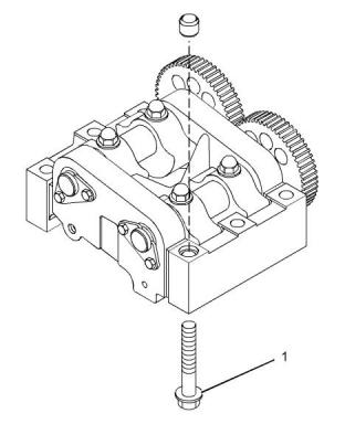
i05124109
Rocker Shaft
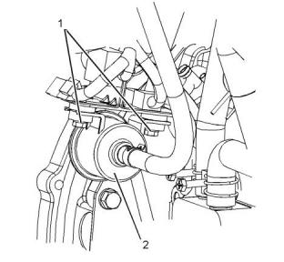
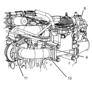
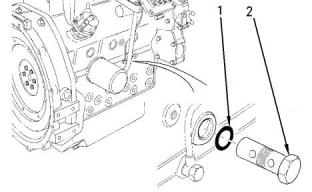
Illustration 8
g03327470
Typical example
(2) Fuel transfer pump
(1) Tighten the fasteners to the following torque.
......................................................13.7 N·m (121 lb in)
Illustration 10
g01440959
i05097794
Typical example
Lifter Group
Note: Before assembly, lubricate the components
with clean engine oil.
(1) Tighten the setscrews to the following torque.
...........................................................10 N·m (89 lb in)
(2) Tighten the nuts to the following torque. .....33 N·m
(24 lb ft)
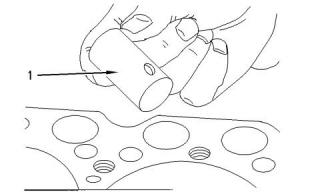
Illustration 9
g00692979
Typical example
Clearance between the lifter (1) and the bore in the
engine for the lifter
Standard maximum clearance..............0.058 mm
(0.0023 inch)
Repair limit ......................0.080 mm (0.0031 inch)
This document is printed from SPI². Not for RESALE
![]()
![]()
![]()
![]()
![]()
![]()
![]()
8
KENR9143
Specifications Section
Minimum permissible clearance
......0.030 to 0.093 mm (0.00120 to 0.00366 inch)
Maximum permissible clearance ..............0.2 mm
(0.008 inch)
i05124111
Valve Mechanism Cover
Illustration 11
g01440976
Typical example
(3) Rocker shaft
Diameter of the rocker shaft.... 14.95 to 14.97 mm
(0.5886 to 0.5894 inch)
Service limit..................... 14.87 mm (0.5854 inch)
(4) Tighten the studs to the following torque.
............................................................56 N·m (41 lb ft)
Illustration 13
g01441024
Typical example
(1) Tighten the setscrews for the valve mechanism
cover to the following torque..............10 N·m (89 lb in)
(2) Tighten the setscrews for the connector on the
inlet manifold to the following torque................14 N·m
(10 lb ft)
(3) Tighten the cap nuts for the valve mechanism
cover to the following torque...............14 N·m (10 lb ft)
i05118831
Cylinder Head Valves
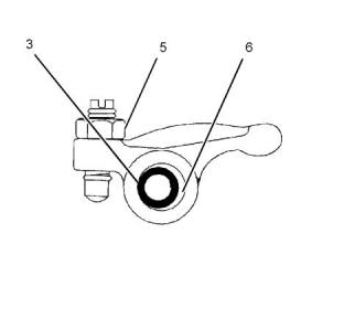
Illustration 12
g01440948
Typical example
(5) Tighten the locknut to the following torque.
............................................................14 N·m (10 lb ft)
(6) Rocker arm clearance on the rocker shaft
This document is printed from SPI². Not for RESALE
![]()
![]()
![]()
![]()
![]()
![]()
![]()
KENR9143
9
Specifications Section
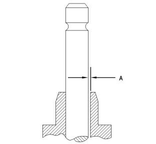
Illustration 14
g00903737
Illustration 15
g00903744
Typical example
Typical example
(5)Exhaust valve guide
(1) Valve spring
(A) Clearance between the exhaust valve and the
valve guide
Standard free length for 403F-15T, 404F-22, and
404F-22T ........................... 35.0 mm (1.378 inch)
403F-15T, 404F-22, and 404F-22T
..........0.050 to 0.075 mm (0.0020 to 0.0030 inch)
Service limit for the standard free length for 403F-
15T, 404F-22, and 404F-22T ................33.5 mm
(1.319 inch)
Service limit.........................0.25 mm (0.010 inch)
(6)Inlet valve guide
Standard test force for 403F-15T, 404F-22, and
404F-22T ........................................79 N (17.8 lb)
(A) Clearance between the inlet valve and the valve
guide
Service limit for the standard test force for 403F-
15T, 404F-22, and 404F-22T ......68.6 N (15.4 lb)
403F-15T, 404F-22, and 404F-22T
..........0.030 to 0.060 mm (0.0012 to 0.0024 inch)
Length under test force for 403F-15T, 404F-22,
and 404F-22T ....................30.4 mm (1.197 inch)
Service limit...........................0.2 mm (0.008 inch)
(7) Exhaust valve stem
(2) Valve guide seal for the exhaust valve
Identification ...........................Black garter spring
Label on the black garter spring................... “EX”
Diameter of the exhaust valve stem for 403F-15T,
404F-22, and 404F-22T ........6.940 to 6.955 mm
(0.2732 to 0.2738 inch)
(3) Valve guide seal for the inlet valve
Identification ...........................Silver garter spring
(4)Valve spring recess for the valve spring
Service limit.........................6.84 mm (0.269 inch)
(8) Inlet valve stem
Diameter of the inlet valve stem for 403F-15T,
404F-22, and 404F-22T ........6.955 to 6.970 mm
(0.27382 to 0.27441 inch)
Service limit.........................6.89 mm (0.271 inch)
This document is printed from SPI². Not for RESALE
![]()

![]()
![]()
![]()
![]()
10
KENR9143
Specifications Section
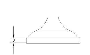
Illustration 16
g00845823
Typical example
(B) Thickness of the valve head .... 0.925 to 1.075 mm
(0.03642 to 0.04232 inch)
Service limit .................................0.5 mm (0.020 inch)
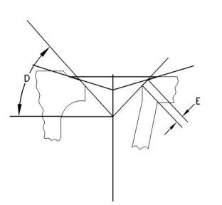
Illustration 18
g00903760
Typical example
(D) Valve seat angle ..................................45 degrees
(E) Contact face
Inlet valve
403F-15T ...................................1.66 to 1.87 mm
(0.0653 to 0.0736 inch)
404F-22, and 404F-22T ............1.50 to 2.00 mm
(0.0591 to 0.0790 inch)
Service limit...........................2.5 mm (0.098 inch)
Exhaust valve
403F-15T ...................................1.66 to 1.73 mm
(0.0653 to 0.0681 inch)
404F-22, and 404F-22T ............1.94 to 2.16 mm
(0.0764 to 0.0850 inch)
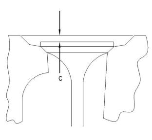
Illustration 17
g00903773
Service limit...........................2.5 mm (0.098 inch)
Typical example
(C) Valve depth below the cylinder head face
i05121549
Cylinder Head
Inlet and exhaust valves for 403F-15T, 404F-22,
and 404F-22T ............................0.65 to 0.95 mm
(0.0256 to 0.0374 inch)
Service limit...........................1.8 mm (0.071 inch)
This document is printed from SPI². Not for RESALE
![]()
![]()
![]()
![]()
![]()
![]()
![]()
KENR9143
11
Specifications Section
Tightening Procedure for the
Cylinder Head
403F-15T Engine
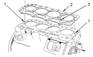
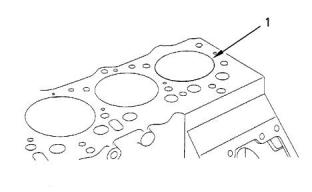
Illustration 19
g00819698
Typical example
(1)Dowel pins
The dowel pins in the cylinder block hold the cylinder
head gasket in the correct position when the cylinder
head is installed.
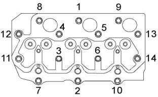
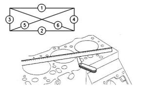
Illustration 20
g01317351
Use the following procedure in order to tighten the
bolts for the cylinder head.
(2)Cylinder head gasket
Table 1
1. Put clean engine oil on the threads of the bolts.
The bolts are tightened in the numerical sequence
that is shown in Illustration 20 .
Selection of Head Gasket for the 403F-15T Engine
Piston Height above Top Face of Cylinder Gasket Thickness
Block
Torque for bolts.................................101 N·m (75 lb ft)
0.60 to 0.69 mm (0.0236 to 0.0272 inch)
1.3 mm
(0.051 inch)
2. Repeat the procedure in step 1 to ensure that all of
0.70 to 0.79 mm (0.0276 to 0.0311 inch)
1.4 mm
(0.055 inch)
the bolts are tightened to the correct torque.
404F-22, and 404F-22T Engines
Table 2
Selection of Head Gasket for the 404F-22, and 404F-22T
Engines
Piston Height below Top Face of Cylinder Gasket Thickness
Block
+0.3 to 0.4 mm (+0.0118 to 0.016 inch)
+0.4 to 0.5 mm (+0.016 to 0.020 inch)
+0.5 to 0.6 mm (+0.020 to 0.024 inch)
1.1 mm
(0.043 inch)
1.2 mm
(0.047 inch)
1.3 mm
(0.051 inch)
(3)The stamped marking on the cylinder head gasket
must face upward. The stamped marking ensures
that the cylinder head gasket is installed correctly.
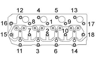
Illustration 21
g01309552
Use the following procedure in order to tighten the
bolts for the cylinder head.
1. Put clean engine oil on the threads of the bolts.
The bolts are tightened in the numerical sequence
that is shown in Illustration 21 .
Torque for bolts.................................101 N·m (75 lb ft)
This document is printed from SPI². Not for RESALE


![]()
![]()
![]()
![]()
![]()
![]()
![]()
12
KENR9143
Specifications Section
2. Repeat the procedure in step 1 to ensure that all of
the bolts are tightened to the correct torque.
Measuring the Distortion of the
Cylinder Head
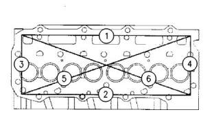
Illustration 22
g00900977
Illustration 23
g00921767
Typical example
(1) Torque for the banjo bolt for the oil supply line
.........................................................18 N·m (13.3 lb ft)
Distortion of the cylinder head...........0.00 to 0.05 mm
(0.000 to 0.002 inch)
(2) Torque for the nuts that secure the turbocharger to
the exhaust manifold ..........................25 N·m (18 lb ft)
Maximum service limit ...............0.12 mm (0.005 inch)
Maximum limit for regrinding the cylinder head
...................................................0.15 mm (0.006 inch)
(3) Torque for the setscrews for the oil drain tube
..............................................................10 N·m (7 lb ft)
Note: Use a straight edge and a feeler gauge to
check the six positions for distortion.
i05192977
Air Pump (ARD Air)
Refer to Systems Operation, Testing and Adjusting,
“Cylinder Head - Inspect” for the procedures for
measuring the cylinder head.
Note: Check the valve depth below the cylinder head
face. Refer to Specifications, “Cylinder Head Valves”
for valve depth.
i02961020
Turbocharger
This document is printed from SPI². Not for RESALE
![]()
![]()
![]()
![]()
![]()
KENR9143
13
Specifications Section
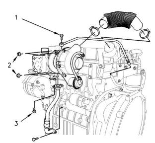
i05192969
Exhaust Cooler (NRS)
(If equipped)
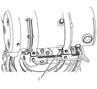
Illustration 24
g03329697
Typical example
(1) Tighten the bolts to the following torque.
..........................................................3.1 N·m (27 lb in)
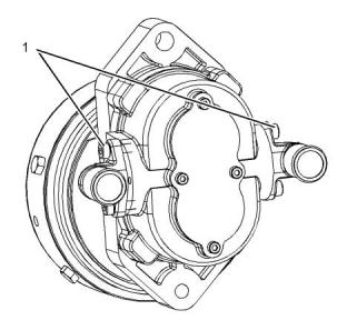
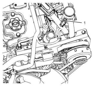
Illustration 26
g03329691
Typical example
(1) Tighten the nut to the following torque.....14.7 N·m
(11 lb ft)
(2) Tighten the bolt to the following torque.
.........................................................14.7 N·m (11 lb ft)
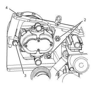
Illustration 25
g03329702
Typical example
(2) Tighten the fasteners to the following torque.
............................................................25 N·m (18 lb ft)
(3) Tighten the fasteners to the following torque.
............................................................25 N·m (18 lb ft)
Note: Bolt (4) should be tightened in order to achieve
the correct belt tension. Refer to Specifications, “Belt
Tension Chart” for the correct belt tension.
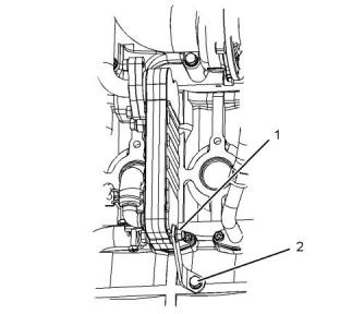
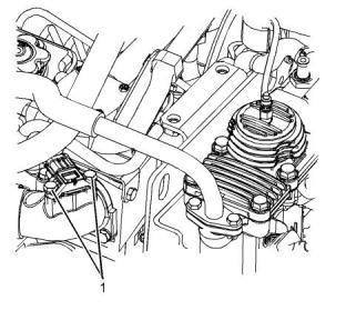
Illustration 27
g03329692
Typical example
This document is printed from SPI². Not for RESALE
![]()
![]()
![]()
![]()
![]()
![]()
![]()
![]()
![]()
14
KENR9143
Specifications Section
(3) Tighten the fasteners to the following torque.
.........................................................14.7 N·m (11 lb ft)
(4) Tighten the fasteners to the following torque.
.........................................................14.7 N·m (11 lb ft)
(5) Tighten the clamps to the following torque.
.............................................................3 N·m (27 lb in)
i05167590
Exhaust Manifold
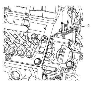
Illustration 29
g03327839
Typical example
(1) Tighten the setscrews to the following torque.
..........................................................9.8 N·m (87 lb in)
Note: The glow plug (2) for the ARD can be replaced.
Refer to Operation and Maintenance Manual, “Glow
Plugs (ARD Combustion) - Replace” for the correct
procedure.
Illustration 28
g00899933
(3) Tighten the pipe to the following torque. .....20 N·m
(15 lb ft)
Typical example
(1) Gasket
(4) Tighten the temperature sensor to the following
torque..................................................30 N·m (22 lb ft)
(2) Tighten the fasteners for the exhaust manifold to
the following torque.............................25 N·m (18 lb ft)
(5) Tighten the studs to the following torque.
............................................................25 N·m (18 lb ft)
i05192974
Exhaust Combustion (ARD)
This document is printed from SPI². Not for RESALE
![]()
![]()
![]()
![]()
![]()
KENR9143
15
Specifications Section
(11) Tighten the bolts to the following torque.
.........................................................32.4 N·m (24 lb ft)
i05118731
Camshaft
Illustration 30
g03329342
Typical example
(6) Tighten the nuts to the following torque. .....25 N·m
(18 lb ft)
Illustration 32
g00819857
Typical example
(7) Tighten the bolts to the following torque......25 N·m
(18 lb ft)
(1) Height of the camshaft lobe for the inlet and
exhaust valves
403F-15T, 404F-22, and 404F-22T
......34.453 to 34.507 mm (1.3564 to 1.3585 inch)
Service limit
403F-15T, 404F-22, and 404F-22T ....... 33.7 mm
(1.3270 inch)
(2) Height of the camshaft lobe for the fuel injection
pump
403F-15T, 404F-22, and 404F-22T
......41.940 to 42.060 mm (1.6512 to 1.6559 inch)
Service limit
403F-15T, 404F-22, and 404F-22T ....... 41.8 mm
(1.6450 inch)
(3) Height of the camshaft lobe for the fuel priming
pump
Illustration 31
g03329350
403F-15T, 404F-22, and 404F-22T
......31.900 to 32.000 mm (1.2559 to 1.2598 inch)
Typical example
(8) Tighten the bolts to the following torque......50 N·m
(37 lb ft)
Service limit
403F-15T, 404F-22, and 404F-22T ....... 30.0 mm
(1.1810 inch)
(9) Tighten the nuts to the following torque. .....25 N·m
(18 lb ft)
(10) Tighten the bolts to the following torque.
............................................................25 N·m (18 lb ft)
This document is printed from SPI². Not for RESALE
![]()
![]()
![]()
![]()
![]()
![]()
![]()
16
KENR9143
Specifications Section
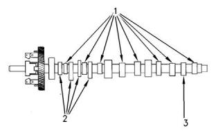
Illustration 33
g00295323
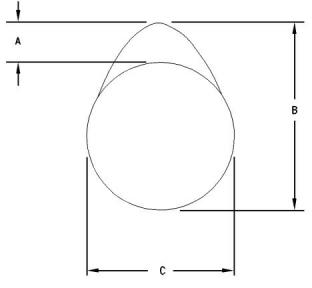
Illustration 34
g01297670
Typical example
Typical example
(A)Actual camshaft lobe lift
(B)Height of the camshaft lobe
(C)Base circle
(4) Tighten the setscrews for the retainer plate for the
camshaft to the following torque........11 N·m (97 lb in)
(5)Retainer plate for the camshaft
(6)Camshaft gear
To determine the lobe lift, use the procedure that
follows:
1. Measure the height of the camshaft lobe (B).
2. Measure the base circle (C).
3. Subtract the base circle that is found in Step 2 from
the height of the camshaft lobe that is found in
Step 1. The difference is the actual camshaft lobe
lift.
This document is printed from SPI². Not for RESALE
![]()
![]()
![]()
![]()
![]()
KENR9143
17
Specifications Section
i02961066
Engine Oil Lines
Illustration 35
g01093847
Typical example
(1) Engine oil line
(2) Washers
Note: The washers must be replaced with new
washers when the engine oil line is removed.
(3) Torque for the banjo bolts................12 N·m (9 lb ft)
i05105509
Engine Oil Relief Valve
Illustration 36
g00820218
Typical example
This document is printed from SPI². Not for RESALE
![]()
![]()
![]()
![]()
18
KENR9143
Specifications Section
Note: When the engine oil relief valve is installed,
ensure that all components are clean. Lightly
lubricate all components with clean engine oil.
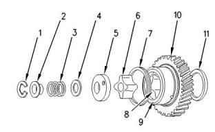
(6) Inner rotor
Number of lobes ................................................. 4
(7) Spring
(1) A new O-ring should be used when the engine oil
relief valve is installed.
(8) Outer rotor
Number of lobes ................................................. 5
(2) Tighten the engine oil relief valve to the following
torque..................................................64 N·m (47 lb ft)
The engine oil pressure at the engine oil relief valve is
the following value.
403F-15T ...............262 to 359 kPa (38 to 52 psi)
404F-22, and 404F-22T ..............352 to 448 kPa
(51 to 65 psi)
Note: Always remove the engine oil relief valve
before removing or installing the crankshaft. Damage
to the engine oil relief valve or damage to the
crankshaft may occur.
i05164987
Engine Oil Pump
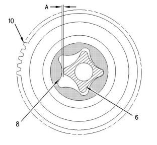
Illustration 38
g00459701
NOTICE
If the front housing is not installed, do not turn the
crankshaft. Damage to the engine may occur.
(A) Clearance between the inner rotor and the outer
rotor is the following value.................0.01 to 0.15 mm
(0.0004 to 0.006 inch)
Service Limit............................0.25 mm (0.0098 inch)
(9) Bushing
(10) Idler gear
(11) Thrust washer
Illustration 37
g00458938
Idler gear and components of the engine oil pump
Type ......................................................Gerotor pump
(1) Circlip
(2) Collar
(3) Spring
(4) Shim
(5) Oil pump cover
This document is printed from SPI². Not for RESALE
![]()
![]()
![]()
![]()
![]()
![]()
![]()
KENR9143
19
Specifications Section
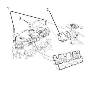
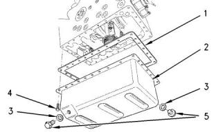
Illustration 40
g00820013
(1) Gasket
(2) Engine oil pan
(3) Washer
Illustration 39
g01088627
(4) Tighten the bolts for the engine oil pan to the
(12) Dial indicator
following torque.....................................11 N·m (8 lb ft)
(B) When the components of the oil pump are
(5) Tighten the drain plugs of the engine oil pan to the
following torque...................................35 N·m (26 lb ft)
installed on the front housing, measurement (B)
between C-clip (1) and collar (2) must not exceed the
following distance. ............................. 0.10 to 0.15 mm
(0.004 to 0.006 inch)
Note: Install a new gasket (1) when the engine oil
pan is removed or replaced.
Oil Suction Tube and Oil Strainer
Service limit ...............................0.20 mm (0.008 inch)
The distance between the faces is adjusted with
shims (4). The following sizes of shims are available:
• 0.10 mm
• 0.15 mm
• 0.20 mm
• 0.50 mm
i02586871
Engine Oil Pan
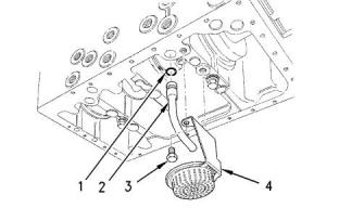
Illustration 41
g00820021
(1) O-ring
(2) Oil suction tube
(3) Tighten the bolts for the oil strainer to the following
torque....................................................11 N·m (8 lb ft)
(4) Strainer
Note: Install a new O-ring (1) in the hole of the
cylinder block when the oil suction tube is removed or
replaced.
This document is printed from SPI². Not for RESALE
![]()
![]()
![]()
![]()
![]()
![]()
![]()
20
KENR9143
Specifications Section
i05192960
403F-15Tand 404F-22 engines.........80° to 84°C
(176° to 183°F)
Crankcase Breather
404F-22T engines ......................... 82 °C (180 °F)
Fully open temperature of the water temperature
regulator................................................ 95 °C (203 °F)
Water Temperature Regulator
Housing for 403F-15T, 404F-22, and
404F-22T Engines
Illustration 42
g03327834
Typical example
(1) Tighten the setscrews to the following torque.
..........................................................7.5 N·m (66 lb in)
Illustration 44
g00820265
i05105490
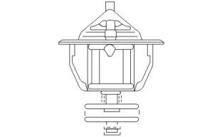
Water Temperature Regulator
Illustration 45
g01114379
Water temperature regulator for naturally aspirated
engines
Illustration 43
g00877006
Typical example
Opening temperature of the water temperature
regulator
This document is printed from SPI². Not for RESALE
![]()
![]()
![]()
![]()
![]()
![]()
![]()
![]()
KENR9143
21
Specifications Section
Service limit .........................84.200 mm (3.3150 inch)
Illustration 46
g01114381
Water temperature regulator for turbocharged
engines
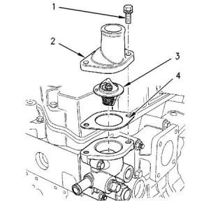
Illustration 48
g00901145
Typical example
Note: Ensure that the water temperature regulator is
seated correctly in the housing.
Flatness of the top of the cylinder block ......Less than
0.05 mm (0.002 inch)
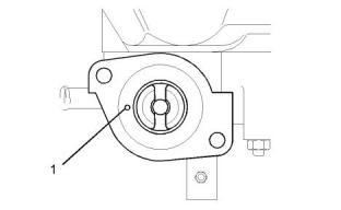
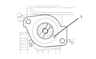
Note: Ensure that the jiggle pin (1) on the water
temperature regulator is correctly positioned. Refer to
illustrations 45 and 46 .
Service limit ...............................0.12 mm (0.005 inch)
Note: Use a straight edge and a feeler gauge to
check the six positions for flatness.
(1) Torque for the two setscrews for the water
temperature regulator housing ...........14 N·m (10 lb ft)
Note: The front bush for the crankshaft must be
installed with the chamfer toward the cylinder block.
Ensure that the oil hole in the front bush for the
crankshaft is aligned with the oil hole in the cylinder
block.
(2) Cover
(3) Water temperature regulator
(4) Gasket
i05095147
i05094774
Crankshaft
Cylinder Block
Illustration 47
g00904878
Typical example
(1) Diameter of the bore in the cylinder block
.............84.000 to 84.019 mm (3.3071 to 3.3078 inch)
This document is printed from SPI². Not for RESALE
![]()
![]()
![]()
![]()
![]()
![]()
![]()
22
KENR9143
Specifications Section
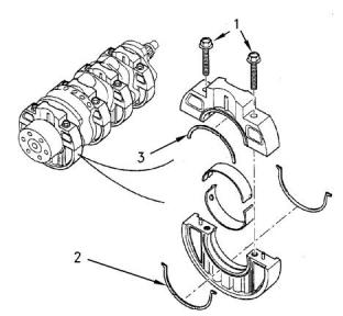
Note: The top thrust washer (3) is used only on the
404F-22, and 404F-22T engines
Ensure that the oil grooves of all of the thrust washers
are toward the crankshaft.
Illustration 51
g00904925
Typical example
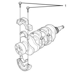
Illustration 49
g01113243
Typical crankshaft for a three cylinder engine
(4) Tighten the retaining bolts for the crankshaft to the
following torque...................................52 N·m (38 lb ft)
(5) Tighten the allen head screws to the following
torque..................................................27 N·m (20 lb ft)
Crankshaft end play........................... 0.10 to 0.30 mm
(0.0040 to 0.0118 inch)
Service limit .............................0.50 mm (0.0197 inch)
Note: If the crankshaft end play exceeds the service
limit, check the thrust washers for wear.
Refer to Specifications, “Connecting Rod Bearing
Journal” for information on the connecting rod bearing
journals of the crankshaft.
Refer to Specifications, “Main Bearing Journal” for
information on the main bearing journals of the
crankshaft.
i05124089
Connecting Rod Bearing
Journal
Illustration 50
g00904902
Typical crankshaft for a four cylinder engine
(1) Tighten the bolts of the holder for the main bearing
to the following torque.........................52 N·m (38 lb ft)
(2) Thrust washers
Table 3
403F-15T, 404F-22, and 404F-22T
Standard thickness ..................... 2.95 to 3.00 mm
(0.1161 to 0.1181 inch)
Diameter of the 403F-15T, 404F-22, and 404F-22T Connecting
Rod Bearing Journals
Journals
Diameter
Service limit
51.964 to 51.975 mm
(2.04582 to 2.04626 inch)
51.90 mm
(2.0433 inch)
Service limit........................2.80 mm (0.1102 inch)
(3)Top thrust washer
Standard
(continued)
This document is printed from SPI². Not for RESALE

![]()
![]()
![]()
![]()
![]()
![]()
![]()
KENR9143
23
Specifications Section
(Table 3, contd)
Undersize
0.25 mm
(0.010 inch)
51.714 to 51.725 mm
(2.03598 to 2.03641 inch)
51.65 mm
(2.0335 inch)
Undersize
0.50 mm
(0.020 inch)
51.464 to 51.475 mm
(2.02614 to 2.02660 inch) (2.0236 inch)(1)
51.40 mm
(1)
If the diameter of the connecting rod bearing journal is less than
the maximum undersize service limit, the crankshaft must be
replaced.
Clearance between the connecting rod bearing and
the connecting rod bearing journal
Standard clearance
403F-15T, 404F-22, and 404F-22T
......0.035 to 0.085 mm (0.00138 to 0.00335 inch)
Service limit....................... 0.20 mm (0.0079 inch)
i05124030
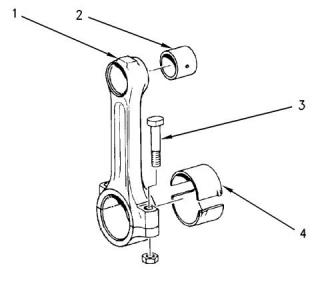
Illustration 52
g00693257
Main Bearing Journal
Typical example
(1) Connecting rod
(2) Piston pin bearing
Table 4
Clearance between the piston pin and the piston
pin bearing (All models) ..........0.010 to 0.025 mm
(0.00040 to 0.00099 inch)
Diameter of Main Bearing Journals
Journals
Diameter
Service limit
67.957 to 67.970 mm
(2.67550 to 2.67597 inch) (2.6732 inch)
67.90 mm
Service limit
403F-15T, 404F-22, and 404F-22T ....... 0.10 mm
(0.004 inch)
Standard
Clearance between the main bearing and the main
bearing journal........................0.044 mm to 0.102 mm
(0.0017 inch to 0.0040 inch)
(3) Torque for the nut and the bolt.......52 N·m (38 lb ft)
(4) Connecting rod bearing
Service limit .............................0.20 mm (0.0079 inch)
Clearance between the connecting rod bore and
the connecting rod bearing ......... 0.10 to 0.30 mm
(0.004 to 0.012 inch)
i05124033
Connecting Rod
Service limit.......................0.70 mm (0.0276 inch)
This document is printed from SPI². Not for RESALE


![]()
![]()
![]()
24
KENR9143
Specifications Section
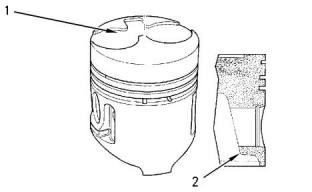
Markings on the Connecting Rod
(2)The Shibaura name that is on the inside of the
piston must align with the stamped number on the
connecting rod.
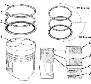
Piston and Piston Rings
Illustration 53
g00555416
Typical example
The pistons and connecting rods are matched to
each cylinder. Note the position of each connecting
rod and piston for correct assembly.
Identification marks (1) on the connecting rod and on
the connecting rod cap must be matched and aligned.
When the connecting rod is installed correctly, the
marks should face the right side of the engine.
Illustration 55
g00845969
Refer to Testing and Adjusting, “Connecting Rod -
Inspect” for the procedure to measure distortion and
parallelism of the connecting rod.
Typical example
Use a feeler gauge to measure the clearance
between the piston ring groove and the piston ring. If
the clearance is greater than the service limit, use a
new piston ring and check the clearance.
i05124083
Piston and Rings
If the clearance is within the service limit, renew the
piston rings. If the clearance is outside of the service
limit, renew the piston.
(1) Top piston ring
Markings on the Piston
Shape of top ring (A)
Naturally aspirated ..............................Barrel face
Turbocharged .................................Half keystone
403F-15T, and 404F-22
Clearance between piston ring groove and top
piston ring.....................................0.07 to 0.11 mm
(0.0028 to 0.0043 inch)
Service limit for clearance of top piston ring
.......................................... 0.25 mm (0.0098 inch)
Gap of top piston ring..................0.20 to 0.35 mm
(0.0079 to 0.0138 inch)
Service limit for gap of top piston ring....... 1.0 mm
(0.039 inch)
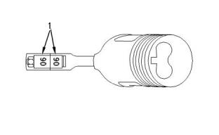
Illustration 54
g00845975
Typical example
Note: It is difficult to measure the wear of the top
piston ring on the 404F-22T turbocharged engines.
When either the intermediate ring or the oil control
ring is outside the service limit, renew all of the rings.
(1)The chamber that is on the top of the piston must
face the right side of the engine.
This document is printed from SPI². Not for RESALE
![]()
![]()
![]()
![]()
![]()
![]()
![]()
KENR9143
25
Specifications Section
Note: Install the letters “T” or “RN” toward the top of
the piston. New top piston rings have a red
identification mark. The identification mark must be
on the left of the ring gap when the top piston ring is
installed on an upright piston.
The oil control ring has two components. The two
components of the oil control ring are installed in the
following order.
1. Spring (D)
Note: New top piston rings for the 404F-22T have a
yellow identification mark. The identification mark
must be on the left of the ring gap when the top piston
ring is installed on an upright piston.
2. Oil control ring (C)
Note: A latch pin is used in order to hold both ends of
the spring of the oil control ring in position. The ends
of the spring of the oil control ring must be 180
degrees opposite the end gap of the oil control ring.
Note: The top surface of the piston ring should be
equally distant from the top face of the cylinder block
at all points before the piston ring end gap is
measured with a feeler gauge.
Note: The top surface of the piston ring should be
equally distant from the top face of the cylinder block
at all points before the piston ring end gap is
measured with a feeler gauge.
(2) Intermediate ring
(4) Piston
Shape of intermediate ring (B) .................... Taper
403F-15T, 404F-22, and 404F-22T
Diameter of the piston skirt
......83.948 to 83.963 mm (3.3050 to 3.3056 inch)
403F-15T, 404F-22, and 404F-22T
Clearance between piston ring groove and
intermediate ring .........................0.04 to 0.08 mm
(0.0016 to 0.0032 inch)
Service limit.........................83.7 mm (3.295 inch)
Service limit for clearance of intermediate ring
..........................................0.25 mm (0.0098 inch)
Clearance of the piston skirt to the cylinder wall
............................................0.0380 to 0.0720 mm
(0.00150 to 0.00283 inch)
403F-15T, and 404F-22
gap of the intermediate ring ............ 0.2 to 0.4 mm
(0.0079 to 0.0157 inch)
Service limit.........................0.25 mm (0.010 inch)
Diameter of the piston pin
......27.994 to 28.000 mm (1.1021 to 1.1024 inch)
404F-22T gap of the intermediate ring
...................... 0.5 to 0.7 mm (0.020 to 0.023 inch)
Service limit.....................27.98 mm (1.1016 inch)
Service limit for gap of intermediate ring
.............................................. 1.2 mm (0.047 inch)
Clearance between the hole for the piston pin
and the piston pin................−0.001 to +0.011 mm
(−0.0004 to +0.0004 inch)
Note: Install the word “Top” toward the top of the
piston. New intermediate rings have a green
identification mark. The identification mark must be
on the left of the ring gap when the intermediate ring
is installed on an upright piston.
Service limit.......................0.02 mm (0.0008 inch)
Refer to Specifications, “Cylinder Head” for the piston
height for a given gasket thickness.
Note: The top surface of the piston ring should be
equally distant from the top face of the cylinder block
at all points before the piston ring end gap is
measured with a feeler gauge.
i05192371
Balancer
(3) Oil control ring
403F-15T, 404F-22, and 404F-22T
Clearance between piston ring groove and oil
control ring ..................................0.02 to 0.06 mm
(0.0008 to 0.0024 inch)
Service limit for clearance of oil control ring
..........................................0.15 mm (0.0059 inch)
Gap of oil control ring..................0.25 to 0.50 mm
(0.0098 to 0.0197 inch)
Service limit for gap of oil control ring....... 1.0 mm
(0.039 inch)
This document is printed from SPI². Not for RESALE
![]()
26
KENR9143
Specifications Section
Illustration 56
g03340077
Typical example
(1) Tighten the setscrews that retain the balancer to
the cylinder block to the following torque..........52 N·m
(38 lb ft)
Illustration 57
g01308682
The backlash between the crankshaft gear and the
balancer gear......................................... 0.2 to 0.4 mm
(0.00787 to 0.01575 inch)
Typical example
(1) Locator hole
(2) Locator pin
(3) Front housing
Note: The balancer has shims to reduce the backlash
on the balancer gear.
i02613910
(4) Tighten the setscrews and nuts to the following
torque....................................................10 N·m (7 lb ft)
Housing (Front)
Note: Note the positions of the setscrews when the
bolts are removed. The setscrews have different
lengths.
(5) Seal protector
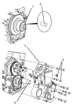
i05105472
Gear Group (Front)
This document is printed from SPI². Not for RESALE
![]()
![]()
![]()
![]()
![]()
KENR9143
27
Specifications Section
Table 5
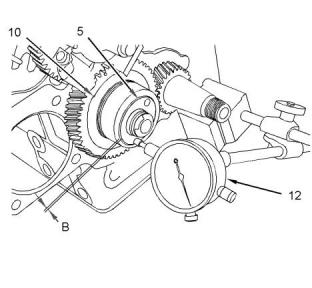
(3) Timing mark on the camshaft gear
Injection timing
(4) Timing mark on the idler gear
Engine
Maximum rated en-
gine speed
Injection timing
(BTDC)(1)
Minimum backlash for all gears..................... 0.08 mm
(0.003 inch)
403F-15T Industrial
engine
2400
2800
3000
16° ± 1°
16° ± 1°
16° ± 1°
Maximum backlash for all gears....................0.25 mm
(0.010 inch)
403F-15T Industrial
engine
Note: If the backlash is greater than the maximum
backlash, replace the camshaft gear, the idler gear,
and the crankshaft gear.
403F-15T Industrial
engine
404F-22 engine
1800
2400
14.5° ± 1°
18° ± 1°
When the idler gear is installed on the shaft of the oil
pump, align a timing mark on idler gear (4) with the
timing mark on crankshaft gear (2). Also, align the
other timing mark on idler gear (4) with the timing
mark on camshaft gear (3).
404F-22 Industrial
engine
404F-22 Industrial
engine
2600
2800
3000
17° ± 1°
17° ± 1°
18° ± 1°
404F-22 Industrial
engine
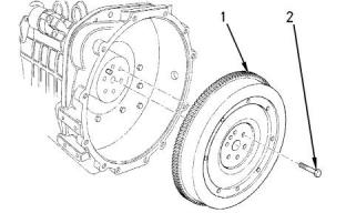
i02590383
Flywheel
404F-22 Industrial
engine
404F-22T engine
1800
2600
15° ± 1°
18° ± 1°
404F-22T Industrial
engine
404F-22T Industrial
engine
2800
3000
19° ± 1°
20° ± 1°
404F-22T Industrial
engine
(1)
Before Top Dead Center
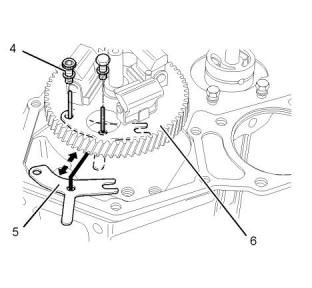
Illustration 59
g00820355
(1) Heat the flywheel ring gear to the following
temperature. ................120° to 150°C (248° to 302°F)
Note: If the ring gear is excessively worn, renew the
ring gear. If excessive wear is not present, remove
the ring gear and install the ring gear at 90 degrees
from the original position. Heat the ring gear evenly.
(2) Tighten the setscrews on the flywheel to the
following torque...................................74 N·m (55 lb ft)
Maximum flywheel runout..........0.20 mm (0.008 inch)
Illustration 58
g01298853
i05164369
Typical example
Flywheel Housing
(1) Feeler gauge
(2) Timing mark on the crankshaft gear
This document is printed from SPI². Not for RESALE

![]()

![]()
![]()
![]()
![]()
28
KENR9143
Specifications Section
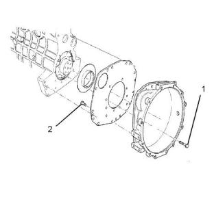
Illustration 60
g01442020
Typical example
(1) Tighten the setscrews for the back plate to the
following torque...................................25 N·m (19 lb ft)
(2) Tighten the setscrews for the flywheel housing to
the following torque.............................25 N·m (19 lb ft)
i05164995
Crankshaft Pulley
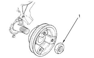
Illustration 61
g00904688
Typical example
(1) Tighten the crankshaft pulley nut to the following
torque.............................................304 N·m (224 lb ft)
This document is printed from SPI². Not for RESALE
![]()
![]()
![]()
![]()
![]()
KENR9143
29
Specifications Section
i05221013
Belt Tension Chart
Table 6
Belt Tension Chart for Alternator and Fan Belts
Gauge Reading
Initial Belt Tension
(1)
Used Belt Tension
(2)
400 to 489 N (90 to 110 lb)
Initial Belt Tension refers to a new belt.
267 to 356 N (60 to 80 lb)
(1)
(2)
Used Belt Tension refers to a belt that has been in operation for 30 minutes or more at the rated speed.
Table 7
Belt Tension Chart for Air Pump Belts
Gauge Reading
Initial Belt Tension(1)
Used Belt Tension(2)
310 N (69 lb)
220 N (49 lb)
(1)
(2)
Initial Belt Tension refers to a new belt.
Used Belt Tension refers to a belt that has been in operation for 30 minutes or more at the rated speed.
i02590411
i05192976
Fan Drive
Engine Lifting Bracket
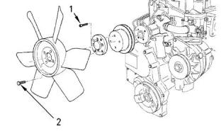
Illustration 62
g00904732
(1) Tighten the allen head screws for the adapter to
the following torque...............................11 N·m (8 lb ft)
(2) Tighten the setscrews for the fan to the following
torque....................................................11 N·m (8 lb ft)
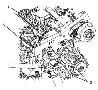
Illustration 63
g03329689
Typical example
(1) Tighten the bolts to the following torque......25 N·m
(18 lb ft)
This document is printed from SPI². Not for RESALE


![]()
![]()
![]()
![]()
![]()
30
KENR9143
Specifications Section
(2) Tighten the bolts to the following torque......50 N·m
(37 lb ft)
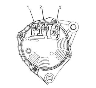
Tighten the nut on the terminal to the following
torque.........................................4.4 N·m (39 lb in)
(2) Terminal “D+”
Tighten the nut on the terminal to the following
torque.........................................4.4 N·m (39 lb in)
(3) Terminal “B+”
Tighten the nut on the terminal to the following.
......................................................7 N·m (62 lb in)
The rotation of the alternator is clockwise when the
alternator is viewed from the pulley.
The regulator of the alternator is sealed. The
regulator is a nonserviceable part.
Polarity ...........................Negative ground to the case
Rotation ...............................................Either direction
Output voltage .....................................................14 V
Rated voltage .......................................................12 V
Rated current output ...................................60 or 85 A
Illustration 64
g03329690
Typical example
(3) Tighten the bolts that secure the bracket to the
following torque...................................50 N·m (37 lb ft)
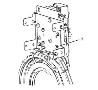
i05124496
Electric Starting Motor
i05124451
Alternator and Regulator
Starting Motor
Illustration 66
g00379835
Starting motor and starting motor solenoid
No load conditions at 25°C (77°F)
Rpm with no load ......................4000 to 6000 rpm
Maximum current ........................................540 A
Current draw with no load ...........................130 A
Voltage .......................................................11.5 V
Rated voltage ................................................12 V
Illustration 65
g03327359
Typical example
(1) Terminal “W”
This document is printed from SPI². Not for RESALE
![]()
![]()
![]()
![]()
![]()
![]()
![]()
KENR9143
31
Specifications Section
Power rating ........................................................2 kW
Power rating ........................................................2 kW
Minimum average cranking rpm ........................... 130
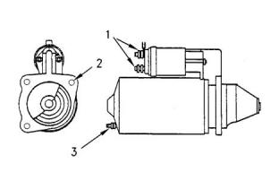
Starting motor solenoid
i05164981
Engine Oil Pressure Switch
Pull-in current .............................................54.5 A
Hold-in current ............................................10.5 A
(1) Tighten the battery terminal nut to the following
torque..................................................15 N·m (11 lb ft)
(2) Tighten the two mounting bolts to the following
torque..................................................50 N·m (37 lb ft)
(3) Tighten the nut for the switch terminal to the
following torque................1.0 to 1.3 N·m (9 to 12 lb in)
Maximum resistance of the starter cable at 20°C
(68°F) and at 12 V .......................................0.04 ohms
i05189560
Coolant Temperature Sensor
Illustration 68
g01335504
Typical example
Note: The engine oil pressure switch can be found in
two positions.
(1) Engine oil pressure switch that is located on the
valve mechanism cover
Torque for the engine oil pressure switch
....................................................11 N·m (97 lb in)
403F-15T, 404F-22, and 404F-22T ............(Amp)
Brown connector
Pressure rating
403F-15T, 404F-22, 404F-22T ..............29.4 kPa
(4.26 psi)
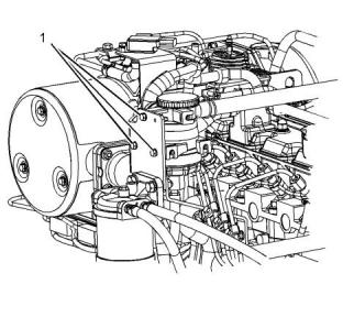
Illustration 67
g03325662
Typical example
(2) Engine oil pressure switch that is located on the
cylinder block
(1) Tighten the coolant temperature sensor to the
following torque................................17.2N·m (13 lb ft)
Torque for the engine oil pressure switch
.....................................................23 N·m (17 lb ft)
403F-15T, 404F-22, and 404F-22T ............(Amp)
Black connector
This document is printed from SPI². Not for RESALE
![]()
![]()
![]()
![]()
![]()
32
KENR9143
Specifications Section
Pressure rating
403F-15T, 404F-22, and 404F-22T .......68.9 kPa
(10.0 psi)
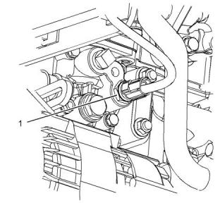
i05189692
Boost Pressure Sensor
(If equipped)
Illustration 70
g03325818
Typical example
(1) Tighten the sensor to the following torque.
.........................................................17.2 N·m (13 lb ft)
i05181637
Temperature Sensor (DPF
Inlet)
Illustration 69
g03325764
Typical example
(1) Tighten the fasteners that secure the sensor to the
following torque....................................3 N·m (27 lb in)
i05189704
Inlet Manifold Temperature
Sensor
Illustration 71
g03322423
Typical example
This document is printed from SPI². Not for RESALE
![]()
![]()
![]()
![]()
![]()
![]()
![]()
KENR9143
33
Specifications Section
(1) Tighten the temperature sensor to the following
torque..................................................30 N·m (22 lb ft)
i05181638
Temperature Sensor (DOC
Inlet)
Illustration 73
g03323793
Typical example
Illustration 72
g03322426
Typical example
(1) Tighten the temperature sensor to the following
torque..................................................30 N·m (22 lb ft)
i05189664
Speed/Timing Sensor
Illustration 74
g03323794
Typical example
(1) (2) Tighten the sensor to the following torque.
.............................................................7 N·m (62 lb in)
i05124491
Glow Plugs
This document is printed from SPI². Not for RESALE
![]()
![]()
![]()
![]()
![]()
![]()
![]()
34
KENR9143
Specifications Section
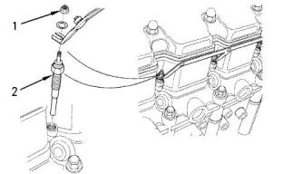
Illustration 75
g00904843
Typical example
(1) Tighten the nut on the bus bar to the following
torque................................................1.2 N·m (11 lb in)
(2) Tighten the glow plugs to the following torque.
............................................................18 N·m (13 lb ft)
This document is printed from SPI². Not for RESALE
![]()
![]()
![]()
KENR9143
35
Index Section
Index
A
F
Air Pump (ARD Air).......................................... 12
Alternator and Regulator.................................. 30
Fan Drive......................................................... 29
Flywheel .......................................................... 27
Flywheel Housing............................................ 27
Fuel Injection Lines............................................ 5
Fuel Injection Pump........................................... 5
Fuel Injector....................................................... 6
Fuel Transfer Pump........................................... 6
B
Balancer .......................................................... 25
Belt Tension Chart ........................................... 29
Boost Pressure Sensor (If equipped) .............. 32
G
C
Gear Group (Front).......................................... 26
Glow Plugs ...................................................... 33
Camshaft......................................................... 15
Connecting Rod............................................... 23
Markings on the Connecting Rod................. 24
Connecting Rod Bearing Journal..................... 22
Coolant Temperature Sensor........................... 31
Crankcase Breather......................................... 20
Crankshaft....................................................... 21
Crankshaft Pulley ............................................ 28
Cylinder Block.................................................. 21
Cylinder Head.................................................. 10
Measuring the Distortion of the Cylinder Head
................................................................... 12
Tightening Procedure for the Cylinder Head
....................................................................11
Cylinder Head Valves ........................................ 8
H
Housing (Front)................................................ 26
I
Important Safety Information............................. 2
Inlet Manifold Temperature Sensor.................. 32
L
Lifter Group........................................................ 7
M
E
Main Bearing Journal....................................... 23
Electric Starting Motor ..................................... 30
Starting Motor............................................... 30
Engine Design ................................................... 4
403F-15T Engine .......................................... 4
404F-22 Engine ............................................ 4
404F-22T Engine .......................................... 5
Engine Lifting Bracket...................................... 29
Engine Oil Lines............................................... 17
Engine Oil Pan................................................. 19
Oil Suction Tube and Oil Strainer................. 19
Engine Oil Pressure Switch............................. 31
Engine Oil Pump.............................................. 18
Engine Oil Relief Valve.................................... 17
Exhaust Combustion (ARD) ............................ 14
Exhaust Cooler (NRS) (If equipped)................ 13
Exhaust Manifold............................................. 14
P
Piston and Rings ............................................. 24
Markings on the Piston ................................ 24
Piston and Piston Rings............................... 24
R
Rocker Shaft...................................................... 7
S
Specifications Section ....................................... 4
Speed/Timing Sensor...................................... 33
This document is printed from SPI². Not for RESALE
![]()
36
KENR9143
Index Section
T
Table of Contents............................................... 3
Temperature Sensor (DOC Inlet)..................... 33
Temperature Sensor (DPF Inlet)...................... 32
Turbocharger................................................... 12
V
Valve Mechanism Cover.................................... 8
W
Water Temperature Regulator ......................... 20
Water Temperature Regulator Housing for
403F-15T, 404F-22, and 404F-22T Engines
................................................................... 20
This document is printed from SPI². Not for RESALE
![]()
This document is printed from SPI². Not for RESALE
©2013 Perkins Engines Company Limited
All Rights Reserved
This document is printed from SPI². Not for RESALE