 English
 Espaol
 Franais
 阿拉伯
阿拉伯 中文
中文 Deutsch
 Italiano
 Português
 日本
日本 韩国
韩国 български
 hrvatski
 esky
esky Dansk
Dansk Nederlands
 suomi
suomi Ελληνικ
 印度
印度 norsk
norsk Polski
 Roman
Roman русский
 Svenska
珀金斯Perkins1104D-E44T and 1104D-E44TA技术资料供应商,珀金斯Perkins1104D-E44T and 1104D-E44TA技术资料技术价格规格咨询服务,珀金斯Perkins1104D-E44T and 1104D-E44TA技术资料零配件供应,珀金斯Perkins1104D-E44T and 1104D-E44TA技术资料售后服务中心,珀金斯Perkins1104D-E44T and 1104D-E44TA技术资料,珀金斯Perkins1104D-E44T and 1104D-E44TA技术资料详细的技术参数,

珀金斯Perkins1104D-E44T and 1104D-E44TA技术资料(英文)
详细描述
Specifications
1104D-E44T and 1104D-E44TA
Industrial Engines
NP (Engine)
NR (Engine)
This document has been printed from SPI2. NOT FOR RESALE.
![]()
![]()
![]()
![]()

Important Safety Information
Most accidents tha t involve produc t op eration, ma intena nc e and repair are caus ed by failure to
ob serve basic safety rules or precautions . An accident can often be avoided by recog nizing pote ntially
ha za rdous situations before an accident oc curs . A person mus t be alert to pote ntial ha za rds. This
person should also ha ve the ne cessary training, skills and tools to perform the se func tions properly.
Improper operation, lubrication, maintenance or repair of this product can be dangerous and
could result in injury or death.
Do not operate or perform any lubrication, maintenance or repair on this product, until you have
read and understood the operation, lubrication, maintenance and repair information.
Sa fety precautions and warning s are provided in this ma nua l and on the produc t. If the se ha za rd
warning s are not he eded, bod ily injury or death could oc cur to you or to othe r persons .
The ha za rds are identified by the “Safety Alert Symb ol” and followed by a “Signa l Word” suc h as
“DANGER”, “WARNING” or “CAUTION”. The Sa fety Alert “WARNING” label is shown below.
The me aning of this safety alert symb ol is as follows:
Attention! Become Alert! Your Safety is Involved.
The me ssage tha t appears und er the warning explains the ha za rd and can be either written or
pictorially presente d.
Op erations tha t ma y caus e produc t dama ge are identified by “NOTICE” labels on the produc t and in
this pub lication.
Perkins cannot anticipate every possible circumstance that might involve a potential hazard. The
warnings in this publication and on the product are, therefore, not all inclusive. If a tool, procedure,
work method or operating technique that is not specifically recommended by Perkins is used,
you must satisfy yourself that it is safe for you and for others. You should also ensure that the
product will not be damaged or be made unsafe by the operation, lubrication, maintenance or
repair procedures that you choose.
The informa tion, specifications , and illustrations in this pub lication are on the basis of informa tion tha t
was available at the time tha t the pub lication was written. The specifications , torque s, pressure s,
me asure me nts , adjustme nts , illustrations , and othe r items can cha ng e at any time. These cha ng es can
affect the service tha t is given to the produc t. Ob tain the comp lete and mos t current informa tion before
you start any job. Pe rkins dealers or Pe rkins distributors ha ve the mos t current informa tion available.
When replacement parts are required for this
product Perkins recommends using Perkins
replacement parts.
Failure to heed this warning can lead to prema-
ture failures, product damage, personal injury or
death.
This document has been printed from SPI2. NOT FOR RESALE.
![]()
![]()
UENR4460
3
Table of Contents
Table of Contents
Crankshaft Pulley ...................... ..................... 34
Belt Tensioner......................... ........................ 34
Refrigerant Compressor................. ................ 35
Fan Drive............................ ............................ 35
Engine Lifting Bracket................... .................. 35
Alternator............................ ............................ 36
Starter Motor.......................... ......................... 36
Coolant Temperature Sensor............. ............. 37
Engine Oil Pressure Sensor.............. ............. 37
Boost Pressure Sensor.................. ................. 38
Inlet Manifold Temperature Sensor......... ........ 38
Speed/Timing Sensor................... .................. 38
Electronic Control Module ............... ............... 39
Glow Plugs .......................... ........................... 39
SpecificationsSection
Engine Design ......................... ......................... 4
Fuel Injection Lines...................... ..................... 4
Fuel Injection Pump..................... ..................... 5
Fuel Injectors.......................... .......................... 7
Fuel Filter Base (Twin Secondary Fuel Filter
Base) ............................... ............................... 8
Fuel Priming Pump (Mechanical Priming
Pump) ............................... .............................. 8
Fuel Priming Pump (Electric Fuel Priming
Pump) ............................... .............................. 9
Fuel Manifold (Rail)...................... ..................... 9
Lifter Group........................... .......................... 10
Rocker Shaft.......................... ......................... 10
Valve Mechanism Cover................. ................ 12
Cylinder Head Valves ................... .................. 12
Cylinder Head......................... ........................ 13
Turbocharger......................... ......................... 14
Exhaust Manifold...................... ...................... 15
Camshaft............................ ............................ 16
Camshaft Bearings..................... .................... 16
Engine Oil Filter Base................... .................. 17
Engine Oil Cooler...................... ...................... 18
Engine Oil Pump....................... ...................... 19
Engine Oil Pressure.................... .................... 21
Engine Oil Bypass Valve ................ ................ 21
Engine Oil Pan........................ ........................ 22
Crankcase Breather.................... .................... 23
Water Temperature Regulator and Housing.. . 24
Water Pump.......................... .......................... 24
Cylinder Block......................... ........................ 25
Crankshaft (Spheroidal Graphite Iron (SGI)
Index Section
Index................................ ............................... 41
Crankshaft).......................... ......................... 26
Crankshaft Seals ...................... ...................... 26
Connecting Rod Bearing Journal (Spheroidal
Graphite Iron Crankshaft)............... .............. 27
Main Bearing Journal (Spheroidal Graphite Iron
(SGI) Crankshaft)..................... ..................... 27
Connecting Rod (For Use With Spheroidal
Graphite Iron (SGI) Crankshaft).......... .......... 27
Piston and Rings ...................... ...................... 29
Piston Cooling Jet...................... ..................... 30
Balancer .......................................................... 30
Front Housing and Covers............... ............... 31
Gear Group (Front)..................... .................... 32
Flywheel .......................................................... 33
Flywheel Housing...................... ..................... 33
This document has been printed from SPI2. NOT FOR RESALE.
![]()
4
UENR4460
Specifications Section
SpecificationsSection
When the crankshaft is viewed from the front of the
engine, the crankshaft rotates in the following
direction: .....................................................Clockwise
i02657590
Engine Design
When the camshaft is viewed from the front of the
engine, the camshaft rotates in the following direction:
.....................................................................Clockwise
The front of the engine is opposite the flywheel end.
The left side and the right side of the engine are
viewed from the flywheel end. The No. 1 cylinder is
the front cylinder.
i05535328
Fuel Injection Lines
Contact with high pressure fuel may cause fluid
penetration and burn hazards. High pressure fuel
spray may cause a fire hazard. Failure to follow
these inspection, maintenance and service in-
structions may cause personal injury or death.
Refer to Operation and Maintenance Manual,
“General Hazard Information and High Pressure Fuel
Lines” before adjustments and repairs are performed.
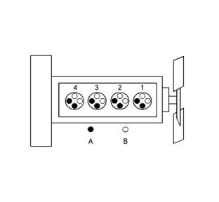
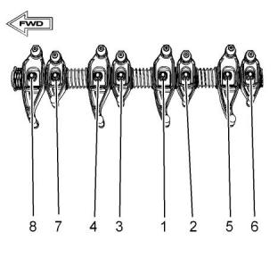
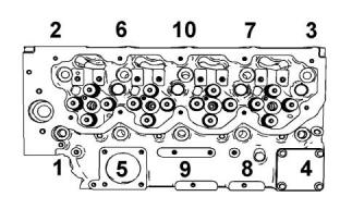
Illustration 1
g01335181
Cylinder and valve location
NOTICE
(A) Exhaust valve
(B) Inlet valve
Refer to Systems Operation, Testing and Adjust-
ing, “Cleanliness of Fuel System Components”
for detailed information on the standards of clean-
liness that must be observed during ALL work on
the fuel system.
Bore ............................................105 mm (4.133 inch)
Stroke .........................................127 mm (5.000 inch)
Displacement........................................4.4 L (269 in3)
Cylinder arrangement ........................................In-line
Type of combustion ..............................Direct injection
Compression ratio
Ensure that all adjustments and repairs are
performed by authorized personnel that have had the
correct training.
Turbocharged engines and turbocharged
aftercooled engines ....................................16.2:1
Number of cylinders .................................................. 4
Valves per cylinder .................................................... 4
Valve lash
Inlet valve..........................0.35 mm (0.0138 inch)
Exhaust valve....................0.35 mm (0.0138 inch)
Firing order .....................................................1, 3, 4, 2
This document has been printed from SPI2. NOT FOR RESALE.
![]()
![]()
![]()
![]()
![]()
![]()
![]()
UENR4460
5
Specifications Section
Illustration 2
g03506656
Typical example
(1) (2) Tighten the nuts on the fuel injection lines to
the following torque.............................32 N·m (24 lb ft)
NOTICE
Refer to Systems Operation, Testing and Adjust-
ing, “Cleanliness of Fuel System Components”
for detailed information on the standards of clean-
liness that must be observed during ALL work on
the fuel system.
(3) Tighten the screw to the following torque.
............................................................22 N·m (16 lb ft)
(4) Tighten the screws for the clamps to the following
torque...................................................4 N·m (35 lb in)
i05547015
Fuel Injection Pump
Note: The timing of the fuel injection pump will need
to be checked by trained personnel. In order to check
the timing of the fuel injection pump, refer to Systems
Operation, Testing and Adjusting, “Fuel Injection
Pump Timing - Check”.
This document has been printed from SPI2. NOT FOR RESALE.

![]()
![]()
![]()
![]()
6
UENR4460
Specifications Section
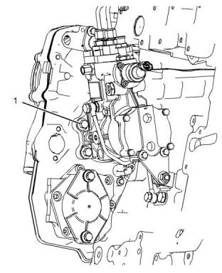
Illustration 3
g03543157
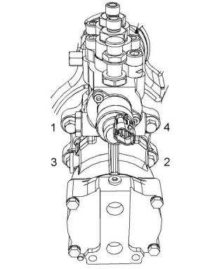
Illustration 4
g03346360
Typical example
Typical example
(1) Tighten the bolts to an initial torque.............10 N·m
(89 lb in)
Tighten the bolts in the sequence that is in illustration
4 . Tighten the bolts to the following torque......44 N·m
(32 lb ft)
This document has been printed from SPI2. NOT FOR RESALE.
![]()
![]()
![]()
![]()
![]()
UENR4460
7
Specifications Section
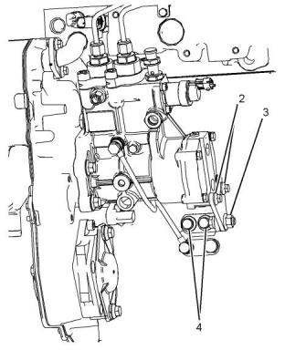
(2) Tighten the bolts to the following torque......22 N·m
(16 lb ft)
(3) Tighten the fasteners to the following torque.
............................................................44 N·m (32 lb ft)
(4) Tighten the bolts to the following torque......44 N·m
(32 lb ft)
Note: The fasteners (2), (3), and (4) should be
tightened in the sequence that is shown in illustration
6
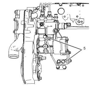
Illustration 5
g03543140
Typical example
Illustration 7
g03543096
Typical example
(5) Tighten the bolts to the following torque......10 N·m
(89 lb in)
i05295515
Fuel Injectors
Refer to Operation and Maintenance Manual,
“General Hazard Information and High Pressure Fuel
Lines” before adjustments and repairs are performed.
NOTICE
Refer to Systems Operation, Testing and Adjust-
ing, “Cleanliness of Fuel System Components”
for detailed information on the standards of clean-
liness that must be observed during ALL work on
the fuel system.
Illustration 6
g03543138
Typical example
This document has been printed from SPI2. NOT FOR RESALE.
![]()
![]()
![]()
![]()
![]()

![]()
![]()
![]()
![]()
8
UENR4460
Specifications Section
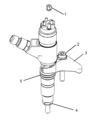
Illustration 8
g03344528
Illustration 9
g03590389
Typical example
Typical example
(3) Clamp
(4) Washer
(5) O ring seal
(1) Tighten the bolts to the following torque......22 N·m
(16 lb ft)
(1) Torque for the nuts..........................2 N·m (18 lb in)
(2) Tighten the bolt to the following torque. ......21 N·m
(15 lb ft)
(2) Torque for the bolt in the clamp for the fuel
injection nozzle...................................27 N·m (20 lb ft)
(3) Tighten the bolts to the following torque......22 N·m
(16 lb ft)
i05547012
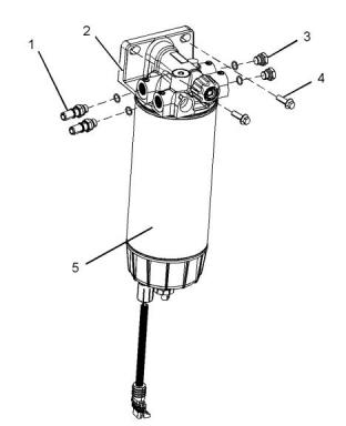
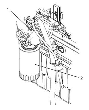
Fuel Filter Base
(Twin Secondary Fuel Filter
Base)
i05258818
Fuel Priming Pump
(Mechanical Priming Pump)
NOTICE
NOTICE
Refer to Systems Operation, Testing and Adjust-
ing, “Cleanliness of Fuel System Components”
for detailed information on the standards of clean-
liness that must be observed during ALL work on
the fuel system.
Refer to Systems Operation, Testing and Adjust-
ing, “Cleanliness of Fuel System Components”
for detailed information on the standards of clean-
liness that must be observed during ALL work on
the fuel system.
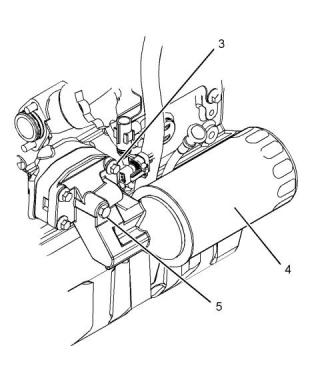
If necessary, install a new fuel filter element to
canister (5). Refer to Operation and Maintenance
Manual, “Fuel System Primary Filter (Water
Separator) Element - Replace” for the correct
procedure.
If necessary, install a new fuel filter to canister (4).
Refer to Operation and Maintenance Manual, “Fuel
System Secondary Filter - Replace” for the correct
procedure.
This document has been printed from SPI2. NOT FOR RESALE.
![]()
![]()
![]()
![]()
![]()
![]()
![]()
![]()
![]()
UENR4460
9
Specifications Section
If necessary, install a new fuel filter element to
canister (5). Refer to Operation and Maintenance
Manual, “Fuel System Primary Filter (Water
Separator) Element - Replace” for the correct
procedure.
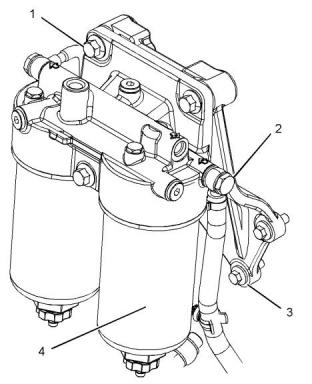
Illustration 11
g03348301
Typical example
(2) Primary fuel filter base
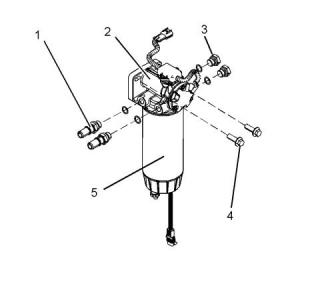
Illustration 10
g03347830
Typical example
(2) Primary fuel filter base
(1) Tighten the connectors to the following torque.
............................................................20 N·m (15 lb ft)
(1) Tighten the connectors to the following torque.
............................................................20 N·m (15 lb ft)
(3) Tighten the plugs to the following torque.
............................................................20 N·m (15 lb ft)
(3) Tighten the plugs to the following torque.
............................................................20 N·m (15 lb ft)
(4) Tighten the bolts to the following torque......44 N·m
(32 lb ft)
(4) Tighten the bolts to the following torque......44 N·m
(32 lb ft)
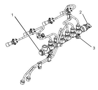
i05536738
Fuel Manifold (Rail)
i05259696
Fuel Priming Pump
(Electric Fuel Priming Pump)
Refer to Operation and Maintenance Manual,
“General Hazard Information and High Pressure Fuel
Lines” before adjustments and repairs are performed.
NOTICE
NOTICE
Refer to Systems Operation, Testing and Adjust-
ing, “Cleanliness of Fuel System Components”
for detailed information on the standards of clean-
liness that must be observed during ALL work on
the fuel system.
Refer to Systems Operation, Testing and Adjust-
ing, “Cleanliness of Fuel System Components”
for detailed information on the standards of clean-
liness that must be observed during ALL work on
the fuel system.
This document has been printed from SPI2. NOT FOR RESALE.
![]()
![]()
![]()
![]()
![]()
![]()
![]()
![]()
![]()
10
UENR4460
Specifications Section
Illustration 12
g03506648
Illustration 13
g01344742
Typical example
(A) Diameter of the lifter body....18.987 to 19.012 mm
(0.7475 to 0.7485 inch)
(1) Tighten the fuel pressure relief valve to the
following torque.................................100N·m (74 lb ft)
Bore diameter in the cylinder block
(2) Tighten the fuel pressure sensor to the following
torque..................................................70 N·m (52 lb ft)
...............19.05 to 19.082 mm (0.7500 to 0.7513 inch)
Clearance
(3) Tighten the bolts to the following torque......22 N·m
(16 lb ft)
Clearance of the lifter..............0.038 to 0.095 mm
(0.0015 to 0.0037 inch)
i02676273
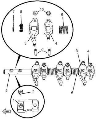
i05535190
Lifter Group
Rocker Shaft
This document has been printed from SPI2. NOT FOR RESALE.
![]()
![]()
![]()

![]()
![]()
UENR4460
11
Specifications Section
(9) Adjuster
(10) Locknut
Torque for the locknut...................27 N·m (20 lb ft)
Illustration 15
g03506066
Tightening sequence
Illustration 14
g01455342
Typical example
Tighten the fasteners in the sequence that is in
illustration 15 . Tighten the fasteners to the following
torque..................................................35 N·m (25 lb ft)
(1) Pedestal
(2) Locator
(3) Inlet rocker arm
Diameter of the rocker arm bore
............................................25.013 to 25.051 mm
(0.98476 to 0.98626 inch)
(4) Exhaust rocker arm
Diameter of the rocker arm bore
............................................25.013 to 25.051 mm
(0.98476 to 0.98626 inch)
Clearance
Maximum clearance of both the rocker arm bores
........................................0.089 mm (0.0035 inch)
The service limit for both rocker arm bores
..........................................0.17 mm (0.0067 inch)
(5) Rocker shaft
Diameter of the rocker shaft
......24.962 to 24.987 mm (0.9828 to 0.9837 inch)
(6) Spring
(7) Snap ring
(8) Spring
This document has been printed from SPI2. NOT FOR RESALE.
![]()
![]()
![]()
![]()
![]()
12
UENR4460
Specifications Section
i05535194
Valve Mechanism Cover
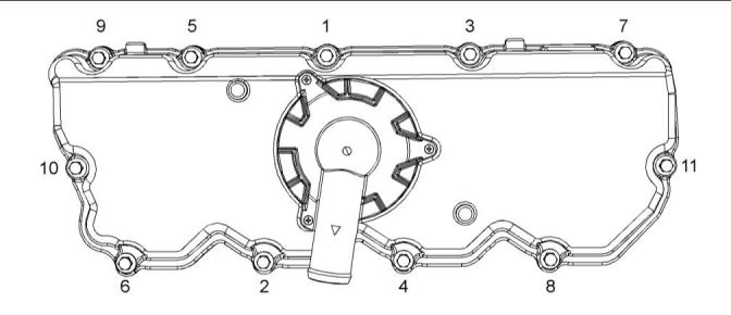
Illustration 16
g03506070
Typical example
Tighten the bolts for the valve mechanism cover in
the sequence that is shown in illustration 16 to the
following torque...................................22 N·m (16 lb ft)
i02657602
Cylinder Head Valves
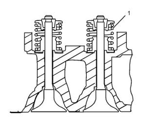
Illustration 17
g01335203
Typical example
The valve spring (1) may be used on the inlet valve or
the exhaust valve. When the valve springs are
replaced the valve springs must be replaced in pairs.
This document has been printed from SPI2. NOT FOR RESALE.
![]()
![]()
![]()
![]()
UENR4460
13
Specifications Section
Table 1
i02934444
The load for the valve spring
The length of the valve spring
31.5 mm (1.2402 inch)
Cylinder Head
161.5 to 178.5 N
(36.3 to 40.1 lb)
337.9 ± 373.5 N (76 ± 84 lb)
21.5 mm (0.8465 inch)
Illustration 19
g01250785
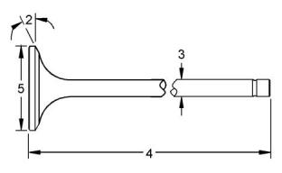
Illustration 18
g01335204
Typical example
(2) Valve face angle
Lubricate the threads and the underside of the head
bolts with clean engine oil.
Inlet .....................................................30 degrees
Exhaust ..............................................45 degrees
Tighten the bolts in the sequence that is shown in
illustration 19 to the following torque.........50 N·m
(37 lb ft)
(3) Valve stem diameter
Inlet....5.942 to 5.957 mm (0.2339 to 0.2345 inch)
Exhaust...................................5.927 to 5.942 mm
(0.2333 to 0.2339 inch)
Tighten the bolts again to the following torque.
...................................................100N·m (74 lb ft)
Tighten the head bolts to the additional amount.
..........................................................225 degrees
Clearance
Minimum thickness of cylinder head .........100.95 mm
(3.9744 inch)
Maximum clearance of the inlet valve stem
..........................................0.05 mm (0.0020 inch)
The service limit for the inlet valve stem
..........................................0.08 mm (0.0031 inch)
Clearance
Maximum clearance of the exhaust valve stem
........................................0.065 mm (0.0026 inch)
The service limit for the inlet valve stem
..........................................0.09 mm (0.0035 inch)
(4) Length of valve
Inlet valve........................107.925 to 108.375 mm
(4.2490 to 4.2667 inch)
Exhaust valve..................107.703 to 108.153 mm
(4.2403 to 4.2580 inch)
(5) Valve head
Diameter of inlet valve head ......................35 mm
(1.3780 inch)
Diameter of exhaust valve head ................33 mm
(1.2992 inch)
This document has been printed from SPI2. NOT FOR RESALE.

![]()
![]()
![]()
![]()
![]()
14
UENR4460
Specifications Section
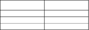
Illustration 20
g01455374
Note: The maximum distortion of the bottom face of
the cylinder head is given in table 2 .
Table 2
Maximum Permissible
Dimension
Distortion
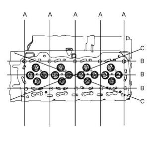
Illustration 21
g01335214
Typical example
Width (A)
Length (B)
0.03 mm (0.0018 inch)
0.05 mm (0.0019 inch)
0.05 mm (0.0019 inch)
(1) Valve guide bores
Diagonal Line (C)
Inlet and exhaust..................... 5.979 to 5.992 mm
(0.2354 to 0.2359 inch)
(2) Valve depths
Inlet....0.905 to 1.163 mm (0.0356 to 0.0458 inch)
The service limit for the depth of the inlet valve
.......................................... 1.41 mm (0.0555 inch)
Exhaust...................................0.876 to 1.131 mm
(0.0345 to 0.0445 inch)
The service limit for the exhaust valve depth
.......................................... 1.38 mm (0.0543 inch)
i05775908
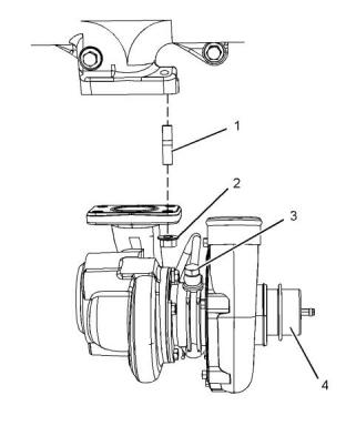
Turbocharger
This document has been printed from SPI2. NOT FOR RESALE.
![]()
![]()
![]()
![]()
![]()
UENR4460
15
Specifications Section
Illustration 22
g03544117
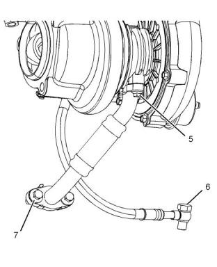
Illustration 23
g03544119
Typical example
Typical example
(1) Tighten the studs to the following torque.
............................................................18 N·m (13 lb ft)
(5) Tighten the bolt to the following torque. ........9 N·m
(80 lb in)
(2) Tighten the nuts to the following torque. .....44 N·m
(32 lb ft)
(6) Tighten the bolt to the following torque. ......18 N·m
(13 lb ft)
(3) Tighten the bolt to the following torque. ......18 N·m
(13 lb ft)
(7) Tighten the bolts to the following torque......22 N·m
(16 lb ft)
(4) Actuator
i02873699
The maximum test pressure for the wastegate
..................................................112 kPa (16.2445 psi)
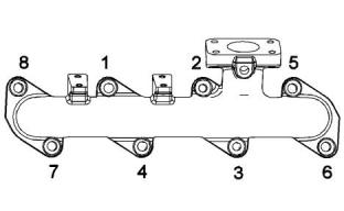
Exhaust Manifold
The movement for the rod actuator .................... 1 mm
(0.0394 inch)
Table 3
The pressure for the
Engine kW
wastegate
106 - 90
90 - 74.5
74.5 - 55
170 kPa (25 psi)
151 kPa (22 psi)
136 kPa (20 psi)
This document has been printed from SPI2. NOT FOR RESALE.

![]()
![]()
![]()
![]()
![]()
16
UENR4460
Specifications Section
Illustration 24
g01430662
Illustration 26
g01195129
Typical example
Typical example
Tighten the exhaust manifold bolts in the sequence
that is shown in illustration 24 to the following torque.
............................................................40 N·m (30 lb ft)
(2) Bolt
Tighten the bolt to the following torque......95 N·m
(70 lb ft)
i02526614
(3) The diameters of the camshaft journals are given
in the following tables.
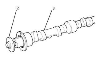
Camshaft
Table 4
Camshaft Journals
Standard Diameter
50.711 to 50.737 mm
(1.9965 to 1.9975 inch)
1
50.457 to 50.483 mm
(1.9865 to 1.9875 inch)
2
3
49.949 to 49.975 mm
(1.9665 to 1.9675 inch)
Maximum wear on the camshaft journals...... 0.05 mm
(0.0021 inch)
Check the camshaft lobes for visible damage. If a
new camshaft is installed you must install new lifters.
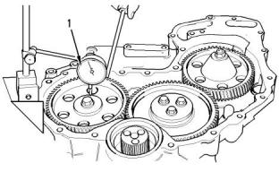
i02658683
Camshaft Bearings
Illustration 25
g00987750
Checking the end play of the camshaft
(1) End play of a camshaft.............0.126 to 0.558 mm
(0.0050 to 0.0220 inch)
Maximum permissible end play of a worn camshaft
.................................................0.62 mm (0.0244 inch)
This document has been printed from SPI2. NOT FOR RESALE.

![]()
![]()
![]()
![]()
![]()
![]()
![]()
UENR4460
17
Specifications Section
Illustration 27
g01335770
Illustration 28
g01455385
Typical example
Typical example
(1) The diameter of the installed camshaft bearing
.............50.787 to 50.848 mm (1.9995 to 2.0019 inch)
(1) Setscrew
Tighten the setscrews to the following torque.
........................................................22 N·m (16 ft)
i02934454
Engine Oil Filter Base
(2) Engine oil filter
Tighten the engine oil filter to the following torque.
.......................................................12 N·m (8 lb ft)
This document has been printed from SPI2. NOT FOR RESALE.
![]()

![]()
![]()
![]()
![]()
18
UENR4460
Specifications Section
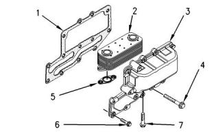
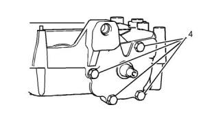
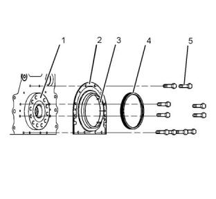
Illustration 30
g00952614
Typical example
(1) Joint
(2) Oil cooler
(3) Housing
(4) Setscrew
(5) Seal
(6) Setscrew
(7) Setscrew
Illustration 29
g01455386
Typical example
(3) Setscrew
Tighten the setscrews to the following torque.
........................................................22 N·m (16 ft)
(4) Engine oil filter
Tighten the engine oil filter to the following torque.
.......................................................12 N·m (8 lb ft)
(5) Plug
Tighten the plug to the following torque.....12 N·m
(8 lb ft)
Illustration 31
g01335773
i02658685
Setscrews
Engine Oil Cooler
Tighten the setscrews (7) to the following torque.
.....................................................22 N·m (16 lb ft)
Setscrews
Tighten the setscrews (4) and (6) in the sequence
that is in illustration 31 to the following torque.
.....................................................22 N·m (16 lb ft)
This document has been printed from SPI2. NOT FOR RESALE.
![]()
![]()
![]()
![]()
![]()
![]()
![]()
UENR4460
19
Specifications Section
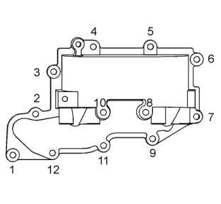
i05663178
Engine Oil Pump
Engines with Balancer Group
Type ...............................Gear-driven differential rotor
Number of lobes
Inner rotor ........................................................... 6
Outer rotor ..........................................................7
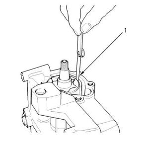
Illustration 33
g00989236
Inner rotor
(2) Clearance of inner rotor to outer rotor
.................0.050 to 0.200 mm (0.0020 to 0.0079 inch)
Illustration 32
g00989248
The oil pump for the balancer
(1) Clearance of the outer rotor to the body
...................0.130 to 0.24 mm (0.0050 to 0.0094 inch)
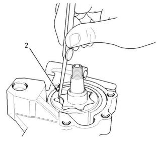
Illustration 34
g00989217
The end play for the rotor
(3) End play of rotor assembly
Inner rotor.....................................0.04 to 0.11 mm
(0.0016 to 0.0043 inch)
Outer rotor...................................0.04 to 0.00 mm
(0.0016 to 0.0043 inch)
This document has been printed from SPI2. NOT FOR RESALE.
![]()
![]()
![]()
![]()
![]()
![]()
![]()
20
UENR4460
Specifications Section
Inner rotor ...........................................................5
Outer rotor ..........................................................6
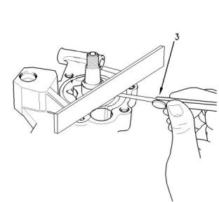
Illustration 35
g01455406
The end cover
Illustration 37
g00938064
(4) Torque for cover bolts for oil pump..............26 N·m
(19 lb ft)
The oil pump
(1) Clearance of the outer rotor to the body
.............0.205 to 0.315 mm (0.00807 to 0.01240 inch)
Illustration 36
g01335780
Idler gear and pump gear
Illustration 38
g00938061
Note: Replace the idler gear bolt (5) and the nut for
the oil pump gear (6).
Checking the clearance
(2) Clearance of inner rotor to outer rotor
.................0.040 to 0.127 mm (0.0015 to 0.0050 inch)
(5) Tighten the idler gear bolt to the following torque.
............................................................26 N·m (19 lb ft)
Note: Set the engine to the TC position. Refer to
Systems Operation, Testing and Adjusting Manual,
“Finding Top Center Position for No. 1 Piston”. Install
the balancer. Refer to Disassembly and Assembly,
“Balancer - Install”. Install the gear for the oil pump
and tighten the nut (6).
(6) Tighten the nut to the following torque........95 N·m
(70 lb ft)
Tighten the bolts that hold the balancer to the cylinder
block to the following torque...............54 N·m (40 lb ft)
Engines without Balancer Group
Type ...............................Gear-driven differential rotor
Number of lobes
Illustration 39
g00938799
Checking the end play
(3) End play of rotor assembly
This document has been printed from SPI2. NOT FOR RESALE.
![]()
![]()
![]()
![]()
![]()
![]()
![]()
![]()
![]()
![]()
![]()
UENR4460
21
Specifications Section
Inner rotor................................0.038 to 0.089 mm
(0.0014 to 0.0035 inch)
Outer rotor...................................0.04 to 0.09 mm
(0.00157 to 0.00354 inch)
Tighten the bolts that hold the front cover of the oil
pump assembly to the following torque............26 N·m
(19 lb ft)
i01958104
Engine Oil Pressure
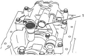
Illustration 41
g00921377
Relief valve and spring
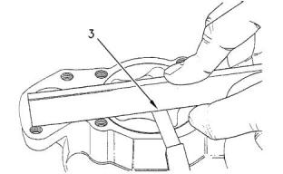
The minimum oil pressure at the maximum engine
speed and at normal operating temperature is the
following value...................................300 kPa (43 psi)
(1) Tighten the plug for the relief valve to the following
torque..................................................35 N·m (26 lb ft)
(2) Plunger
i05663157
Diameter of the plunger.......19.139 to 19.225 mm
(0.75350 to 0.75689 inch)
Engine Oil Bypass Valve
Clearance of plunger in bore....... 0.06 to 0.09 mm
(0.00236 to 0.00354 inch)
(3) Spring
Installed in the Oil Pump
Length of the spring ........80.94 mm (3.1866 inch)
Installed in the Balancer
Illustration 40
g00919893
Typical engine oil pump
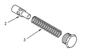
Illustration 42
g00919890
Plug
This document has been printed from SPI2. NOT FOR RESALE.
![]()
![]()
![]()
![]()
![]()

![]()
![]()
22
UENR4460
Specifications Section
Front sealant
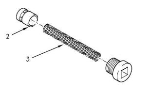
Illustration 43
g00921379
The relief valve for the balancer
(1) Tighten the plug for the relief valve to the following
torque..................................................35 N·m (26 lb ft)
(2) Plunger
Diameter of the plunger...........14.46 to 14.48 mm
(0.5692 to 0.5700 inch)
Illustration 44
g01254690
Applying sealant
Clearance of the plunger in the bore
..............0.04 to 0.08 mm (0.0015 to 0.0031 inch)
Apply Tooling (A) to the cylinder block and to the
timing case.
(3) Spring
Note: Apply a sealant bead of 3.5 mm (0.1378 inch)
that is shown in illustration 44 .
Length of the spring .............67 mm (2.6378 inch)
Rear sealant
i04315734
Note: Install the rear oil seal before sealant is applied
Engine Oil Pan
to the bridge.
Table 5
Required Tools
Tool
Part Number
Part Description
Loctite 5900
Qty
A
-
1
Illustration 45
g01254887
Applyin, g sealant
ApplyTooling (A) to the bridge. The sealant must not
protrude more than 5 mm (0.1969 inch) above the
bridge.
This document has been printed from SPI2. NOT FOR RESALE.

![]()
![]()
![]()
![]()
![]()
![]()
![]()
UENR4460
23
Specifications Section
Unfiltered Breather
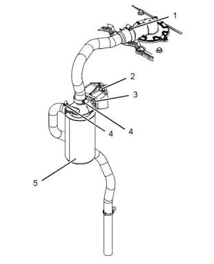
Illustration 46
g01255016
Typical example
Illustration 47
g03506659
Typical example
(1) Tighten the four front bolts in position (X) to the
following torque...................................22 N·m (16 lb ft)
Align the outlet of the breather to the flexible pipe.
(1) Clamp
Tighten the remaining bolts to the following torque.
............................................................22 N·m (16 lb ft)
Tighten the clamp to the following torque.
......................................................5 N·m (44 lb in)
(2) Drain plug
Tighten the drain plug for the engine oil pan to the
following torque............................34 N·m (25 lb ft)
(2) Tighten the setscrew to the following torque.
............................................................22 N·m (16 lb ft)
i05536751
Crankcase Breather
This document has been printed from SPI2. NOT FOR RESALE.
![]()

![]()
![]()

![]()
![]()
24
UENR4460
Specifications Section
Filtered Breather
Table 6
Required Tools
Part Description
Loctite 575
Tool
Part Number
Qty
A
-
1
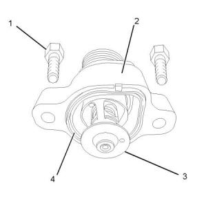
Illustration 49
g01253716
Illustration 48
g03506661
Typical example
Typical example
Note: Apply Tooling (A) to the O-ring (4) in order to
install the water temperature regulator housing (2).
(1) Clamps
(1) Tighten the bolts that fasten the housing to the
following torque...................................44 N·m (32 lb ft)
Tighten the clamps to the following torque.
......................................................5 N·m (44 lb in)
(2) Water temperature regulator housing
(3) Water temperature regulator
(2) (3) Setscrews
Tighten the setscrews to the following torque.
.....................................................22 N·m (16 lb ft)
Opening temperature..........................82° to 87°C
(179.6000° to 156.6000°F)
Full opening temperature...... 95 °C (203.0000 °F)
Minimum stroke at full temperature..............9 mm
(0.3543 inch)
(4) Tighten the clamps to the following torque.
.............................................................3 N·m (27 lb in)
(5) Canister
Tighten the canister to the following torque.
..................................................12 N·m (106 lb in)
i02363605
Water Pump
i05775915
Water Temperature Regulator
and Housing
This document has been printed from SPI2. NOT FOR RESALE.
![]()
![]()
![]()
![]()
![]()
UENR4460
25
Specifications Section
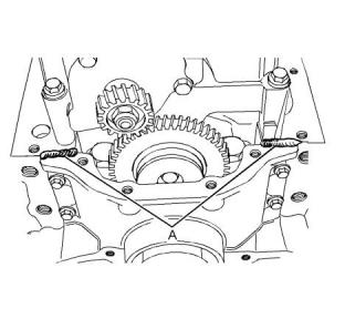
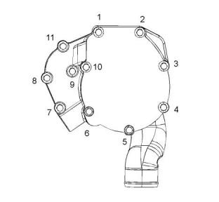
Illustration 50
g01183807
Tightening sequence
Tighten the setscrews in the numerical sequence that
is shown in illustration 50 to the following torque.
............................................................22 N·m (16 lb ft)
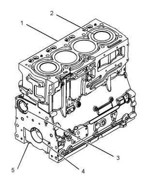
Illustration 51
g01335800
Cylinder block
i04135329
Cylinder Block
(1) Cylinder block
(2) Cylinder bore....................105.000 to 105.025 mm
(4.1338 to 4.1348 inch)
The maximum permissible wear for the cylinder bore
.................................................0.15 mm (0.0059 inch)
(3) Camshaft bearings
Diameter of the bushing in the cylinder block for
the number 1 camshaft bearing
......55.563 to 55.593 mm (2.1875 to 2.1887 inch)
Diameter of the bore in the cylinder block for the
number 2 camshaft journal
......50.546 to 50.597 mm (1.9900 to 1.9920 inch)
Diameter of the bore in the cylinder block for the
number 3 camshaft journal
......50.038 to 50.089 mm (1.9700 to 1.9720 inch)
(4) Main bearings
Bore in the cylinder block for the main bearings
......80.416 to 80.442 mm (3.1660 to 3.1670 inch)
Install the main bearing cap bolts (5). Refer to
Disassembly and Assembly, “Crankshaft Main
Bearings - Remove and Install” or Disassembly and
Assembly, “Crankshaft - Install” for the correct
procedure.
This document has been printed from SPI2. NOT FOR RESALE.
![]()
![]()
![]()
![]()
![]()
26
UENR4460
Specifications Section
(5) Main bearing cap bolts
Note: The timing mark is toward the outside of the
crankshaft when the gear is installed on the
crankshaft.
Evenly tighten the main bearing cap bolts. Torque
for the main bearing cap bolts..................245 N·m
(180 lb ft)
(5) Crankshaft end play
Note: Ensure that the crankshaft can rotate freely.
The end play of a new crankshaft
.................. 0.05 to 0.38 mm (0.002 to 0.015 inch)
Maximum crankshaft end play................ 0.51 mm
(0.020 inch)
i05568790
Crankshaft
(Spheroidal Graphite Iron (SGI)
Crankshaft)
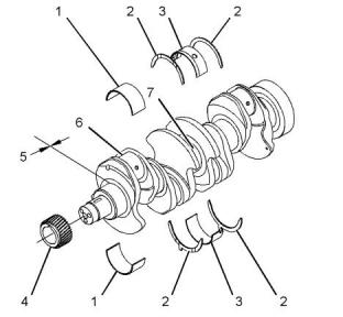
(6) Connecting rod journal. Refer to Specifications,
“Connecting Rod Bearing Journal” for more
information on the connecting rod bearing journals.
(7) Main bearing journal. Refer to Specifications,
“Main Bearing Journal” for information on the main
bearing journals.
i02934550
Crankshaft Seals
Illustration 52
g03435603
Typical Example
(1) Connecting rod bearings. Refer to Specifications,
“Connecting Rod Bearing Journal” for more
information on the connecting rod bearing journals
and connecting rod bearings.
Illustration 53
g01455434
(2) Thrust washers
Typical example
Standard thickness ..................... 2.26 to 2.31 mm
(0.089 to 0.091 inch)
(1) Crankshaft
Oversize thickness...................... 2.45 to 2.50 mm
(0.097 to 0.098 inch)
(2) Crankshaft seal
(3) Plastic sleeve
(4) Alignment tool
(3) Main bearings. Refer to Specifications, “Main
Bearing Journal” for information on the main bearing
journals and for information on the main bearings.
(4) Maximum permissible temperature of the gear for
installation on the crankshaft..............180 °C (356 °F)
This document has been printed from SPI2. NOT FOR RESALE.
![]()
![]()
![]()
![]()
![]()
UENR4460
27
Specifications Section
The Shell for the Connecting Rod
Bearings
Standard Bearing Shells
Thickness at center of the shells ... 1.995 to 2.002 mm
(0.0785 to 0.0788 inch)
Width of the connecting rod bearing shells
.................31.47 to 31.73 mm (1.2390 to 1.2492 inch)
Clearance between the bearing shell and the
connecting rod bearing journals .... 0.031 to 0.078 mm
(0.0012 to 0.0031 inch)
i05569069
Main Bearing Journal
(Spheroidal Graphite Iron (SGI)
Crankshaft)
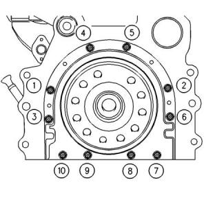
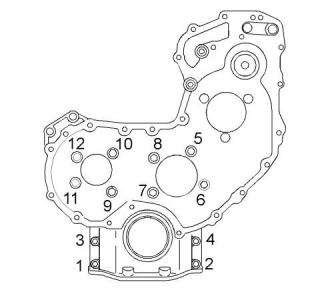
Illustration 54
g00915076
(5) Tighten bolts 1, 2, 3, 4, 5, 6, 7, and 10 in the
sequence that is shown in Illustration 54 to the
following torque...................................22 N·m (16 lb ft)
The original size of the main bearing journal
.............76.159 to 76.180 mm (2.9984 to 2.9992 inch)
Remove the alignment tool.
Tighten bolts 8 and 9 in the sequence that is shown in
Illustration 54 to the following torque...............22 N·m
(16 lb ft)
Maximum permissible wear of the main bearing
journals..................................0.040 mm (0.0016 inch)
Surface finish of bearing journals, crank pins, and
radii..............................Ra 0.0025 microns (10 µ inch)
i05568830
Connecting Rod Bearing
Journal
(Spheroidal Graphite Iron
Crankshaft)
The Shell for the Main Bearings
Standard Bearing Shells
Thickness at center of the shells ... 2.083 to 2.089 mm
(0.0820 to 0.0823 inch)
Width of the main bearing shells ... 31.62 to 31.88 mm
(1.244 to 1.255 inch)
The original size of the connecting rod bearing journal
...............................................67.99 mm (2.6768 inch)
Clearance between the bearing shell and the main
bearing journals..............................0.057 to 0.117 mm
(0.0022 to 0.0046 inch)
Maximum permissible wear of a bearing journal on a
new connecting rod .................0.04 mm (0.0016 inch)
i05569109
Width of the connecting rod bearing journals
.............40.348 to 40.424 mm (1.5885 to 1.5915 inch)
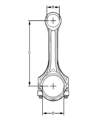
Connecting Rod
(For Use With Spheroidal
Graphite Iron (SGI) Crankshaft)
Surface finish of connecting rod bearing journals and
radii..............................Ra 0.0025 microns (10 µ inch)
This document has been printed from SPI2. NOT FOR RESALE.
![]()
![]()
![]()
28
UENR4460
Specifications Section
Table 7
Bearing Width for the Con- 31.47 mm (1.2390 inch) to
necting Rod
31.73 mm (1.2492 inch)
Bearing Width for the Con- 31.47 mm (1.2390 inch) to
necting Rod Cap
31.73 mm (1.2492 inch)
Thickness of Connecting 1.995 mm (0.0785 inch) to
Rod Bearing at the Center 2.002 mm (0.0788 inch)
Thickness of Connecting 1.995 mm (0.0785 inch) to
Rod Bearing for the Cap at 2.002 mm (0.0788 inch)
the Center
Bearing Clearance
0.031 mm (0.0012 inch) to
0.078 mm (0.0031 inch)
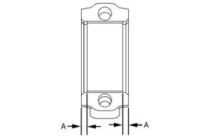
Illustration 55
g03442137
Typical example
Illustration 56
g01356356
Alignment of the bearing shell
The mating surfaces of the connecting rod are
produced by hydraulically fracturing the forged
connecting rod.
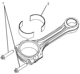
Illustration 57
g03442182
Typical example
(1) Tighten the setscrews for the connecting rod to
the following torque.............................40 N·m (30 lb ft)
(B) Diameter of the bore for the piston pin
.....................43.01 to 43.04 mm (1.693 to 1.694 inch)
Tighten the setscrews for the connecting rod for an
additional 120 degrees. The setscrews for the
connecting rod (1) must be replaced after this
procedure.
(C) Distance between bearing centers
.................219.05 to 219.10 mm (8.624 to 8.626 inch)
(D) Diameter for the bore for the connecting rod
bearing.......................................72.045 to 72.058 mm
(2.8364 to 2.8369 inch)
Note: Always tighten the connecting rod cap to the
connecting rod, when the assembly is out of the
engine. Tighten the assembly to the following torque
15 N·m (133 lb in).
(A) The bearing shell for the connecting rod must be
aligned equally from both ends of the connecting rod.
(2) The bearing shell for the connecting rod
This document has been printed from SPI2. NOT FOR RESALE.

![]()
![]()
![]()
![]()
![]()
![]()
![]()
UENR4460
29
Specifications Section
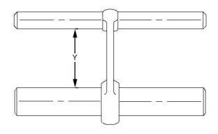
Illustration 58
g01356360
Illustration 59
g01155119
Typical example
Typical example
Connecting rods are color coded. The color code is a
reference for the length (Y) of the connecting rod.
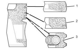
(1) Top compression ring
Refer to table 7 for the different lengths of connecting
rods.
The shape of the top compression ring ....tapered
Table 8
Ring gap......................................0.30 to 0.45 mm
(0.0118 to 0.0177 inch)
Length Grades for Connecting Rods
Length (Y)
Note: When you install a new top compression ring,
make sure that the word “TOP” is facing the top of
the piston. New top piston rings have a yellow
identification mark which must be on the left of the
ring end gap when the top piston ring is installed on
an upright piston.
Grade Letter Color Code
163.310 mm (6.4295 inch) to
163.343 mm (6.4308 inch)
R
O
W
G
P
Red
163.264 mm (6.4277 inch) to
163.297 mm (6.4290 inch)
Orange
163.219 mm (6.4259 inch) to
163.252 mm (6.4272 inch)
(2) Intermediate compression ring
White
Green
Purple
The shape of the intermediate compression ring
...............Internal bevel in the bottom edge with a
tapered face
163.173 mm (6.4241 inch) to
163.206 mm (6.4254 inch)
163.127 mm (6.4223 inch) to
163.160 mm (6.4236 inch)
Width of intermediate compression ring
163.081 mm (6.4205 inch) to
163.114 mm (6.4218 inch)
............2.47 to 2.495 mm (0.0972 to 0.0982 inch)
B
Blue
The clearance between a new intermediate
compression ring and the piston groove in a new
piston............................................0.07 to 0.11 mm
(0.00276 to 0.00433 inch)
i05663413
Piston and Rings
Ring gap......................................0.65 to 0.85 mm
(0.0256 to 0.0335 inch)
Note: When you install a new intermediate
compression ring, make sure that the word “TOP” is
facing the top of the piston. New intermediate rings
have a blue identification mark which must be on the
left of the ring end gap when the top piston ring is
installed on an upright piston.
(3) The oil control ring
Width of oil control ring................2.97 to 2.99 mm
(0.1169 to 0.1177 inch)
This document has been printed from SPI2. NOT FOR RESALE.

![]()
![]()
![]()
![]()
![]()
30
UENR4460
Specifications Section
The clearance between a new oil control ring and
the groove in a new piston..........0.03 to 0.07 mm
(0.0011 to 0.0027 inch)
Ring gap......................................0.25 to 0.45 mm
(0.00984 to 0.01772 inch)
The valve must move freely. Tighten the bolt to the
following torque.......................................9 N·m (7 lb ft)
Piston Cooling Jet Alignment
Note: The oil control ring is a two-piece ring that is
spring loaded. A pin is used in order to hold both ends
of the spring of the oil control ring in position. The
ends of the spring of the oil control ring must be
installed opposite the end gap of the oil control ring.
Note: Ensure that the ring end gaps of the piston
rings are spaced 120 degrees from each other.
Piston
Note: An arrow which is marked on the piston crown
must be toward the front of the engine.
Piston height above cylinder block.... 0.40 to 0.54 mm
(0.0157 to 0.0213 inch)
Width of top groove in the piston ................... Tapered
Width of second groove in new piston
.....................2.56 to 2.58 mm (0.1008 to 0.1016 inch)
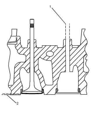
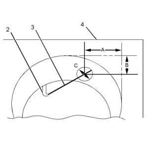
Illustration 61
g01352578
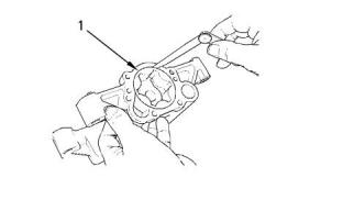
(2) Piston cooling jet
(3) Rod
(4) Cylinder block
Width of third groove in new piston.... 3.02 to 3.04 mm
(0.1189 to 0.1197 inch)
Piston pin
Use the following procedure in order to check the
alignment of the piston cooling jet.
Diameter of a new piston pin
......39.694 to 39.700 mm (1.5628 to 1.5630 inch)
1. Insert rod (3) into the end of the piston cooling jet
(2). Rod (3) has a diameter of 1.70 mm
(0.067 inch). Rod (3) must protrude out of the top
of the cylinder block.
i02696381
Piston Cooling Jet
2. Dimension (A) is 50.75 mm (1.9980 inch) and
dimension (B) is 9.35 mm (0.3681 inch).
Dimension (A) and dimension (B) are tangential to
the cylinder bore (4).
3. The position of the rod (3) must be within
dimension (C). Dimension (C) is 14 mm
(0.5512 inch).
Note: Ensure that the rod (3) can not damage the
piston cooling jet when the alignment is checked. The
piston cooling jets can not be adjusted. If a piston
cooling jet is not in alignment the piston cooling jet
must be replaced.
i05583730
Balancer
Illustration 60
g01352576
(1) Installed piston cooling jets
This document has been printed from SPI2. NOT FOR RESALE.
![]()
![]()
![]()
![]()
![]()
UENR4460
31
Specifications Section
Illustration 62
g00929516
Typical example
(1) Tighten the six mounting bolts to the following
torque..................................................54 N·m (40 lb ft)
Illustration 64
g01332261
i02935111
Typical example
Front Housing and Covers
Tighten the setscrew to the sequence that is shown in
illustration 64 to the following torque. ..............28 N·m
(20 lb ft)
(1) Tighten the bolts that fasten the front cover to the
front housing to the following torque.................22 N·m
(16 lb ft)
The front housing must be aligned to the cylinder
block face..............................+ 0.05 to minus 0.05 mm
(+ 0.0020 to minus 0.0020 inch)
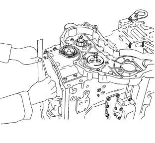
Illustration 65
g00918672
Illustration 63
g01332260
Typical example
Alignment
(2) Tighten the bolts that fasten the water pump to the
front housing to the following torque.................22 N·m
(16 lb ft)
Note: Refer to Specifications, “Water Pump” for the
correct bolt tightening sequence for the water pump.
This document has been printed from SPI2. NOT FOR RESALE.
![]()

![]()
![]()
![]()
![]()
![]()
![]()
![]()
![]()
32
UENR4460
Specifications Section
i05546629
Clearance of idler gear bearing on hub
............0.06 to 0.102 mm (0.0024 to 0.0040 inch)
Gear Group (Front)
Idler gear end play ....................0.10 to 0.205 mm
(0.0039 to 0.0081 inch)
Maximum permissible end play ..............0.38 mm
(0.015 inch)
Idler gear end play with roller bearings
............0.24 to 0.954 mm (0.0094 to 0.0376 inch)
Number of teeth ................................................ 73
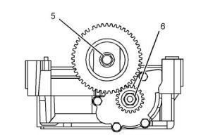
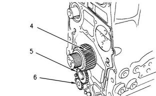
Illustration 67
g00996214
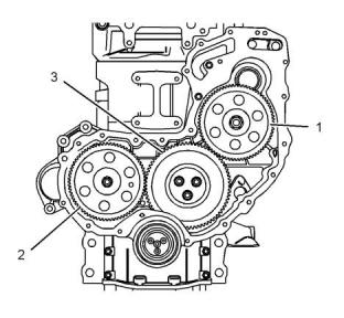
Illustration 66
g01335907
The gear train for the oil pump
Gear train
(4) Crankshaft gear
(1) Fuel injection pump drive gear
Bore diameter of crankshaft gear
..........51.00 to 51.03 mm (2.0079 to 2.0091 inch)
Tighten the nut to the following torque.....160 N·m
(118 lb ft)
Outside diameter of crankshaft hub
......51.021 to 51.002 mm (2.0087 to 2.0079 inch)
Number of teeth ................................................ 68
(2) Camshaft gear
Clearance of gear on crankshaft
....−0.021 to +0.028 mm (−0.0008 to 0.0011 inch)
Torque for the 8.8 graded bolt for the camshaft
gear..............................................95 N·m (70 lb ft)
Torque for the 10.9 graded bolt for the camshaft
gear............................................120 N·m (89 lb ft)
Number of teeth ................................................ 34
(5) Oil pump idler gear
Number of teeth ................................................ 68
(3) Idler gear and hub
Inside diameter of oil pump idler gear bearing
......16.012 to 16.038 mm (0.6304 to 0.6314 inch)
Outside diameter of oil pump idler gear shaft
......15.966 to 15.984 mm (0.6286 to 0.6293 inch)
Tighten the bolts for the idler gear to the following
torque...........................................44 N·m (33 lb ft)
Clearance of oil pump idler gear bearing on shaft
..........0.028 to 0.072 mm (0.0011 to 0.0028 inch)
Width of idler gear and split bearing assembly
......30.165 to 30.135 mm (1.1876 to 1.1864 inch)
End play of the oil pump idler gear
..........0.050 to 0.275 mm (0.0019 to 0.0108 inch)
Inside diameter of idler gear bearings with
flanges.................................50.797 to 50.818 mm
(1.9999 to 2.0007 inch)
(6) Oil pump gear
Outside diameter of idler gear hub
......50.716 to 50.737 mm (1.9967 to 1.9975 inch)
The number of teeth on the oil pump gear ....... 17
Backlash values
This document has been printed from SPI2. NOT FOR RESALE.
![]()
![]()
![]()
![]()
![]()
UENR4460
33
Specifications Section
Backlash between the idler gear (5) and the oil
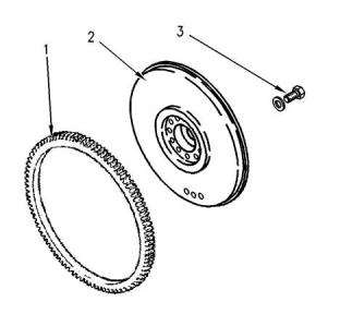
Heat the flywheel ring gear to the following
pump drive gear (6) ....................0.05 to 0.14 mm
(0.0020 to 0.0055 inch)
temperature..................................250 °C (480 °F)
Note: Do not use an oxyacetylene torch to heat the
flywheel ring gear.
Backlash between the oil pump idler gear (5) and
the crankshaft gear (4) ................. 0.8 to 0.23 mm
(0.0315 to 0.0091 inch)
(2) Flywheel
(3) Bolt
Backlash between the idler gear (3) and the
crankshaft gear (4) ...................0.05 to 0.015 mm
(0.0020 to 0.0006 inch)
Tighten the flywheel bolts to the following torque.
................................................ 140 N·m (103 lb ft)
Backlash between the camshaft gear (2) and the
idler gear (3) ...............................0.05 to 0.15 mm
(0.0020 to 0.0059 inch)
i04315754
Flywheel Housing
Backlash between the fuel injection pump gear
(1) and the idler gear (3) .............0.05 to 0.15 mm
(0.0020 to 0.0059 inch)
Table 9
Backlash between the water pump gear (not
shown) and the fuel injection pump gear (1)
..............0.05 to 0.15 mm (0.0020 to 0.0059 inch)
Backlash between the power take-off drive (if
equipped) and the idler gear (3)
Required Tools
Tool
Part Number
Part Description
Loctite 575
Qty
A
-
1
............0.05 to 0.250 mm (0.0020 to 0.0098 inch)
i04121789
Flywheel
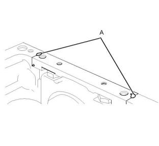
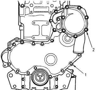
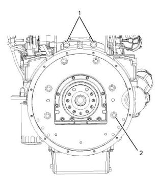
Illustration 69
g01254486
Typical example
Illustration 68
g00584712
Typical example
Setscrew
(1)Tighten the setscrew to the following torque.
.....................................................75 N·m (55 lb ft)
(1) Flywheel ring gear
This document has been printed from SPI2. NOT FOR RESALE.

![]()
![]()
![]()
![]()
![]()
34
UENR4460
Specifications Section
Setscrew
Crankshaft Pulley for the Poly V-
Belt
(2)Tighten the setscrew to the following torque.
.....................................................63 N·m (46 lb ft)
Note: If 12.9 setscrews are installed, apply Tooling
(A) to the setscrews. Tighten the 12.9 setscrews to a
torque of 70 N·m (52 lb ft).
i02659096
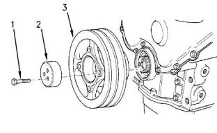
Crankshaft Pulley
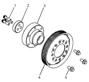
Illustration 71
g01335910
Typical example
(1) Bolt
(2) Thrust block
(3) Crankshaft adapter
(4) Crankshaft pulley
(5) Bolt
Illustration 70
g00915497
(1) Tighten the three bolts for the thrust block to the
following torque.................................115 N·m (85 lb ft)
A standard pulley
Note: Lubricate the threads of the bolts with clean
engine oil before installation.
Note: Recheck the torque of the bolts (1) once.
(5) Tighten the three bolts for the crankshaft pulley to
the following torque.............................78 N·m (58 lb ft)
(1) Tighten the three bolts for the crankshaft pulley to
the following torque...........................115 N·m (85 lb ft)
Note: Recheck the torque of the bolts (1) once.
(2) Thrust block
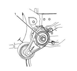
i04083729
Belt Tensioner
(3) Crankshaft pulley
This document has been printed from SPI2. NOT FOR RESALE.
![]()
![]()
![]()
![]()
![]()
UENR4460
35
Specifications Section
(1) Tighten the bolts to the following torque......44 N·m
(32 lb ft)
(2) Tighten the bolts to the following torque......22 N·m
(16 lb ft)
i04921370
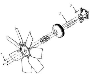
Fan Drive
Illustration 72
g02291813
Typical example
(1) Tighten the bolt to the following torque. ......45 N·m
(33 lb ft)
Note: To install the belt tensioner, refer to
Disassembly and Assembly, “Belt Tensioner -
Remove and Install” for the correct procedure.
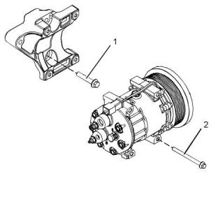
i03629003
Refrigerant Compressor
Illustration 74
g03087078
Typical example
(1) Tighten the locking nuts to the following torque.
............................................................22 N·m (16 lb ft)
(2) Tighten the studs (if equipped) to the following
torque.................................................11 N·m (97 lb in)
(3) Tighten the bolts to the following torque......44 N·m
(32 lb ft)
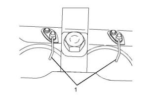
i01721280
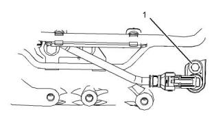
Engine Lifting Bracket
All engines are equipped with two engine lifting
brackets.
Tighten the two bolts on each engine lifting
bracket to the following torque.....44 N·m (32 lb ft)
Illustration 73
g01946810
Typical example
This document has been printed from SPI2. NOT FOR RESALE.
![]()
![]()
![]()
![]()
![]()
![]()
![]()
36
UENR4460
Specifications Section
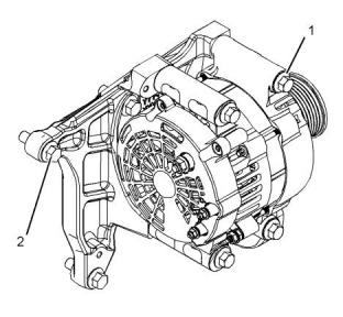
i05732072
Tighten the nut for the alternator pulley to the
following torque...................................95 N·m (70 lb ft)
Alternator
Output
The outputs of the alternators ..........80 Amp, 100
Amp, 120 Amp, or 150 Amp
The 12 V and 24 V Type 1
Alternators
Alternator Bracket
Illustration 76
g02151927
Typical example
(1) Tighten the setscrews that secure the alternator to
the bracket to the following torque......50 N·m (37 lb ft)
(2) Tighten the setscrews that secure the bracket to
the cylinder block to the following torque..........44 N·m
(32 lb ft)
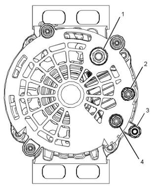
Illustration 75
g02149533
Typical example
(1) Terminal “B+”
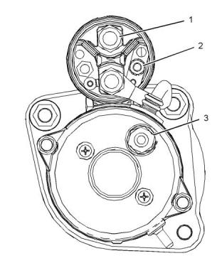
i05583725
Starter Motor
Tighten the nut on the terminal to the following.
...................................................7.5 N·m (66 lb in)
(2) Terminal “D+”
Tighten the nut on the terminal to the following
torque.........................................2.2 N·m (19 lb in)
(3) Terminal “B-” (if equipped)
Tighten the nut on the terminal to the following
torque............................................7 N·m (62 lb in)
(4) Terminal “W”
Tighten the nut on the terminal to the following
torque.........................................2.2 N·m (19 lb in)
This document has been printed from SPI2. NOT FOR RESALE.
![]()
![]()
![]()
![]()
![]()
UENR4460
37
Specifications Section
12 V Starting Motor 3 kW, 4 kW, and
24 V Starting Motor 4.5 kW
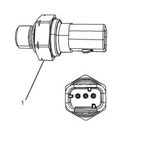
Illustration 78
g01502163
Typical example
(1) Tighten the temperature sensor to the following
torque..................................................20 N·m (15 lb ft)
Output type .....................................................Passive
Operating temperature ..........................−40 to 150 °C
(−40 to 302 °F)
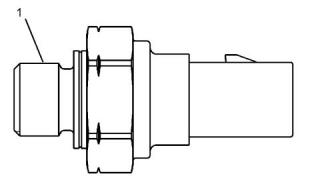
i05535229
Engine Oil Pressure Sensor
Illustration 77
g01943502
Typical example
(1) Tighten the positive terminal nut to the following
torque..................................................15 N·m (11 lb ft)
(2) Tighten the solenoid terminal to the following
torque................................................5.8 N·m (51 lb in)
(3) Tighten the negative terminal nut to the following
torque..................................................18 N·m (13 lb ft)
Rated voltage .......................................................12 V
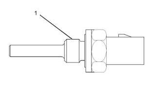
i05535225
Coolant Temperature Sensor
Illustration 79
g01502573
Typical example
(1) Tighten the oil pressure sensor to the following
torque.................................................10 N·m (90 lb in)
Operating temperature ..........................−40 to 125 °C
(−40 to 257 °F)
Operating voltage .................................5.0 ± 0.5 VDC
This document has been printed from SPI2. NOT FOR RESALE.
![]()
![]()
![]()
![]()
![]()
![]()
![]()
38
UENR4460
Specifications Section
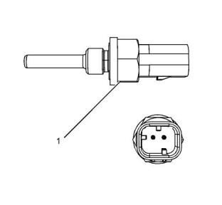
i02652620
Boost Pressure Sensor
Illustration 81
g01332531
Typical example
(1) Sensor
Tighten the sensor to the following torque.
.....................................................20 N·m (15 lb ft)
Illustration 80
g01332534
Typical example
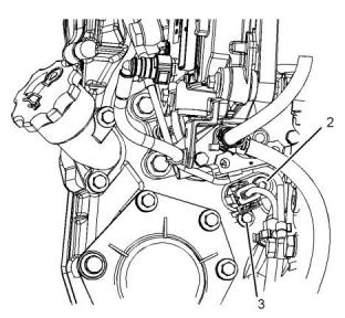
i05535345
Speed/Timing Sensor
(1) Sensor
Tighten the sensor to the following torque.
.......................................................10 N·m (7 lb ft)
i02652622
Inlet Manifold Temperature
Sensor
Illustration 82
g01854256
Typical example
This document has been printed from SPI2. NOT FOR RESALE.
![]()
![]()
![]()
![]()
![]()
![]()
![]()
UENR4460
39
Specifications Section
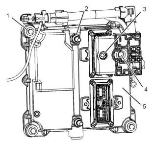
Illustration 83
g03506276
Illustration 84
g03506678
Typical example
Typical example
(5) Electronic control module (ECM)
(1) Tighten the bolt for the crankshaft position sensor
to the following torque.........................14 N·m (10 lb ft)
(1) Tighten the four bolts for the ECM to the following
torque..................................................22 N·m (16 lb ft)
(2) Tighten the setscrew for the sensor to the
following torque...................................14 N·m (10 lb ft)
(2) Tighten the connections (if equipped) to the
following torque...................................17 N·m (13 lb ft)
(3) Tighten the setscrew for the adaptor to the
following torque....................................6 N·m (53 lb in)
(3) Tighten the bolt to the following torque. ........5 N·m
(44 lb in)
i05536783
(4) Tighten the bolt to the following torque. .....6.5 N·m
(58 lb in)
Electronic Control Module
i02659261
Glow Plugs
This document has been printed from SPI2. NOT FOR RESALE.
![]()
![]()
![]()
![]()
![]()
40
UENR4460
Specifications Section
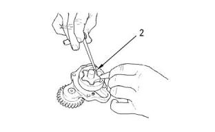
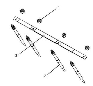
Illustration 85
g01335949
Typical example
Tighten the glow plugs (2) in the cylinder head to the
following torque...................................15 N·m (11 lb ft)
Tighten the nuts (1) for the bus bar (3) that is installed
on top of the glow plugs to the following torque.
.............................................................2 N·m (18 lb in)
Voltage ...................................................12 or 24 volts
This document has been printed from SPI2. NOT FOR RESALE.
![]()
![]()
![]()
UENR4460
41
Index Section
Index
A
Engine Oil Pressure Sensor............................ 37
Engine Oil Pump.............................................. 19
Engines with Balancer Group ...................... 19
Engines without Balancer Group ................. 20
Exhaust Manifold............................................. 15
Alternator......................................................... 36
Alternator Bracket........................................ 36
The 12 Vand 24 V Type 1 Alternators......... 36
B
F
Balancer .......................................................... 30
Belt Tensioner.................................................. 34
Boost Pressure Sensor.................................... 38
Fan Drive......................................................... 35
Flywheel .......................................................... 33
Flywheel Housing............................................ 33
Front Housing and Covers............................... 31
Fuel Filter Base (Twin Secondary Fuel Filter
Base) ............................................................... 8
Fuel Injection Lines............................................ 4
Fuel Injection Pump........................................... 5
Fuel Injectors..................................................... 7
Fuel Manifold (Rail)............................................ 9
Fuel Priming Pump (Electric Fuel Priming
C
Camshaft......................................................... 16
Camshaft Bearings.......................................... 16
Connecting Rod (For Use With Spheroidal
Graphite Iron (SGI) Crankshaft)..................... 27
Connecting Rod Bearing Journal
(Spheroidal Graphite Iron Crankshaft)........... 27
The Shell for the Connecting Rod Bearings
................................................................... 27
Coolant Temperature Sensor........................... 37
Crankcase Breather......................................... 23
Filtered Breather.......................................... 24
Unfiltered Breather....................................... 23
Crankshaft (Spheroidal Graphite Iron (SGI)
Crankshaft).................................................... 26
Crankshaft Pulley ............................................ 34
Crankshaft Pulley for the Poly V-Belt........... 34
Crankshaft Seals ............................................. 26
Cylinder Block.................................................. 25
Cylinder Head.................................................. 13
Cylinder Head Valves ...................................... 12
Pump) .............................................................. 9
Fuel Priming Pump (Mechanical Priming
Pump) .............................................................. 8
G
Gear Group (Front).......................................... 32
Glow Plugs ...................................................... 39
I
Important Safety Information............................. 2
Inlet Manifold Temperature Sensor.................. 38
L
E
Lifter Group...................................................... 10
Electronic Control Module ............................... 39
Engine Design ................................................... 4
Engine Lifting Bracket...................................... 35
Engine Oil Bypass Valve ................................. 21
Installed in the Balancer............................... 21
Installed in the Oil Pump.............................. 21
Engine Oil Cooler............................................. 18
Engine Oil Filter Base...................................... 17
Engine Oil Pan................................................. 22
Front sealant................................................ 22
Rear sealant................................................. 22
Engine Oil Pressure......................................... 21
M
Main Bearing Journal (Spheroidal Graphite
Iron (SGI) Crankshaft).................................... 27
The Shell for the Main Bearings................... 27
P
Piston and Rings ............................................. 29
Piston........................................................... 30
Piston Cooling Jet............................................ 30
This document has been printed from SPI2. NOT FOR RESALE.
![]()
42
UENR4460
Index Section
Piston Cooling Jet Alignment....................... 30
R
Refrigerant Compressor.................................. 35
Rocker Shaft.................................................... 10
S
Specifications Section ....................................... 4
Speed/Timing Sensor...................................... 38
Starter Motor.................................................... 36
12 V Starting Motor 3 kW, 4 kW, and 24 V
Starting Motor 4.5 kW................................. 37
T
Table of Contents............................................... 3
Turbocharger................................................... 14
V
Valve Mechanism Cover..............................., ... 12
W
Water Pump..................................................... 24
Water Temperature Regulator and Housing.... 24
This document has been printed from SPI2. NOT FOR RESALE.
![]()
免费热线
400-082-9096
400-082-9096
整机销售
0731-84424871 18374999699
0731-84424871 18374999699
售后维修
0731-84424872 15580888444
0731-84424872 15580888444
配件销售
0731-84424873 18274802060
0731-84424873 18274802060
手机端

微信公众号