 English
 Espaol
 Franais
 阿拉伯
阿拉伯 中文
中文 Deutsch
 Italiano
 Português
 日本
日本 韩国
韩国 български
 hrvatski
 esky
esky Dansk
Dansk Nederlands
 suomi
suomi Ελληνικ
 印度
印度 norsk
norsk Polski
 Roman
Roman русский
 Svenska
珀金斯Perkins2206D-E13TA操作保养供应商,珀金斯Perkins2206D-E13TA操作保养技术价格规格咨询服务,珀金斯Perkins2206D-E13TA操作保养零配件供应,珀金斯Perkins2206D-E13TA操作保养售后服务中心,珀金斯Perkins2206D-E13TA操作保养,珀金斯Perkins2206D-E13TA操作保养详细的技术参数,


珀金斯Perkins2206D-E13TA操作保养
详细描述
Operation and
Maintenance
Manual
2206D-E13TA Industrial Engine
Engine Operation
Interrupted starts put excessive stress on the drive
train. Interrupted starts also waste fuel. To get the
driven equipment in motion, engage the clutch
smoothly with no load on the equipment. This
method should produce a start that is smooth and
easy. The engine rpm should not increase and the
clutch should not slip.
i06219260
Engine Operation
3. Ensure that the ranges of the gauges are normal
when the engine is operating at one-half of the
rated rpm. Ensure that all gauges operate properly.
Correct operation and maintenance are key factors in
obtaining the maximum life and economy of the
engine. If the directions in the Operation and
Maintenance Manual are followed, costs can be
4. Increase the engine rpm to the rated rpm. Always
increase the engine rpm to the rated rpm before
the load is applied.
minimized and engine service life can be maximized.
Variable Speed Engine
The engine can be operated at the rated rpm after the
engine reaches operating temperature. The engine
will reach normal operating temperature sooner
during a low engine speed (rpm) and during a low-
power demand. This procedure is more effective than
idling the engine at no load. The engine should reach
operating temperature in a few minutes.
5. Apply the load. Begin operating the engine at low
load. Check the gauges and equipment for proper
operation. After normal oil pressure is reached and
the temperature gauge begins to move, the engine
may be operated at full load. Check the gauges
and equipment frequently when the engine is
operated under load.
Gauge readings should be observed and the data
should be recorded frequently while the engine is
operating. Comparing the data over time will help to
determine normal readings for each gauge.
Extended operation at low idle or at reduced load
may cause increased oil consumption and carbon
buildup in the cylinders. This carbon buildup
Comparing data over time will also help detect
abnormal operating developments. Significant
changes in the readings should be investigated.
results in a loss of power and/or poor performance.
i04018232
Constant Speed Engine
Fuel Conservation Practices
Allow the engine to warn up before applying load.
Gauge readings should be observed and the data
should be recorded frequently while the engine is
operating. Comparing the data over time will help to
determine normal readings for each gauge.
Comparing data over time will also help detect
abnormal operating developments. Significant
changes in the readings should be investigated.
The efficiency of the engine can affect the fuel
economy. Perkins design and technology in
manufacturing provides maximum fuel efficiency in all
applications. Follow the recommended procedures in
order to attain optimum performance for the life of the
engine.
• Avoid spilling fuel.
i04038637
Engaging the Driven
Equipment
Fuel expands when the fuel is warmed up. The fuel
may overflow from the fuel tank. Inspect fuel lines for
leaks. Repair the fuel lines, as needed.
• Be aware of the properties of the different fuels.
Use only the recommended fuels. Refer to the
Operations and Maintenance Manual, “Fuel
Recommendations”for further information.
1. Operate the engine at one-half of the rated rpm,
when possible.
• Avoid unnecessary idling.
2. Engage the driven equipment without a load on the
equipment, when possible.
Shut off the engine rather than idle for long periods of
time.
This document has been printed from SPI2. NOT FOR RESALE
![]()
SEBU9072
35
Engine Operation
Fuel Conservation Practices
• Observe the service indicator frequently. Keep the
air cleaner elements clean.
• Ensure that the turbocharger is operating correctly.
For more information refer to this Operation and
Maintenance Manual, “Turbocharger - Inspect”
• Maintain a good electrical system.
One faulty battery cell will overwork the alternator.
This fault will consume excess power and excess
fuel.
• The belt should be in good condition. Refer to the
Systems Operation, Testing and Adjusting, “V-Belt
Test” for further information.
• Ensure that all of the connections of the hoses are
tight. The connections should not leak.
• Ensure that the driven equipment is in good
working order.
• Cold engines consume excess fuel. Utilize heat
from the jacket water system and the exhaust
system, when possible. Keep cooling system
components clean and keep cooling system
components in good repair. Never operate the
engine without water temperature regulators. All of
these items will help maintain operating
temperatures.
This document has been printed from SPI2. NOT FOR RESALE
![]()
36
SEBU9072
Cold Weather Operation
Radiator Restrictions
Cold Weather Operation
The cloud point of the fuel is the temperature at which
waxes naturally found in the diesel fuel begin to form
crystals. The cloud point of the fuel must be below
lowest ambient temperature to prevent filters from
plugging.
i05954317
Radiator Restrictions
Cold Filter Plugging Point is a temperature at which a
particular fuel will pass through a standardized
filtration device. This CFPP gives an estimate of the
lower operability temperature of fuel
Perkins discourages the use of airflow restriction
devices that are mounted in front of radiators. Airflow
restriction can cause the following conditions:
Pour point is the last temperature before the fuel flow
stops and waxing of the fuel will start.
• High exhaust temperatures
• Power loss
Be aware of these properties when diesel fuel is
purchased. Consider the average ambient air
temperature for the engines application. Engines that
are fueled in one climate may not operate well if the
engines are shipped to colder climate. Problems can
result due to changes in temperature.
• Excessive fan usage
• Reduction in fuel economy
If an airflow restriction device must be used, the
device should have a permanent opening directly in
line with the fan hub. The device must have a
Before troubleshooting for low power or for poor
performance in the winter, check the fuel for waxing
minimum opening dimension of at least 770 cm
(120 in
2
The following components can provide a means of
minimizing fuel waxing problems in cold weather:
2
).
A centered opening that is directly in line with the fan
hub is specified in order to prevent an interrupted
airflow on the fan blades. Interrupted airflow on the
fan blades could cause a fan failure.
• Fuel heaters, which may be an OEM option
• Fuel line insulation, which may be an OEM option
Winter and arctic grades of diesel fuel are available in
the countries and territories with severe winters. For
more information refer to the Operation and
Maintenance Manual, “Fuel For Cold Weather
Operation”
Perkins recommends a warning device for the inlet
manifold temperature and/or the installation of an inlet
air temperature gauge. The warning device for the
inlet manifold temperature should be set at 75 °C
(167 °F). The inlet manifold air temperature should
not exceed 75 °C (167 °F). Temperatures that
exceed this limit can cause power loss and potential
engine damage.
Another important fuel property which can affect cold
start and operation of diesel engine is Cetane
number. Detail and requirements of this property are
given in this Operation and Maintenance Manual,
“Fluid Recommendations”.
i05849931
Fuel and the Effect from Cold
Weather
i06093465
Fuel Related Components in
Cold Weather
Note: Only use grades of fuel that are recommended
by Perkins. Refer to this Operation and Maintenance
Manual, “Fluid Recommendations”.
Fuel Tanks
Properties of the diesel fuel can have a significant
effect on the engine cold start capability. It is critical
that the low temperature properties of diesel fuel are
acceptable for the minimum ambient temperature the
engine is expected to see in the operation.
Condensation can form in partially filled fuel tanks.
Top off the fuel tanks after operating the engine.
Fuel tanks should contain some provision for draining
water and sediment from the bottom of the tanks.
Some fuel tanks use supply pipes that allow water
and sediment to settle below the end of the fuel
supply pipe.
Following properties are used to define fuels low
temperature capability:
• Cloud point
Some fuel tanks use supply lines that take fuel
directly from the bottom of the tank. If the engine is
equipped with this system, regular maintenance of
the fuel system filter is important.
• Pour point
• Cold Filter Plugging Point (CFPP)
This document has been printed from SPI2. NOT FOR RESALE
![]()
SEBU9072
37
Cold Weather Operation
Fuel Related Components in Cold Weather
Drain the water and sediment from any fuel storage
tank at the following intervals:
• Weekly
• Oil changes
• Refueling of the fuel tank
This draining will help prevent water and/or sediment
from being pumped from the fuel storage tank and
into the engine fuel tank.
Fuel Heaters
Fuel heaters help to prevent fuel filters from plugging
in cold weather due to waxing. A fuel heater should
be installed in order for the fuel to be heated before
the fuel enters the primary fuel filter.
Select a fuel heater that is mechanically simple, yet
adequate for the application. The fuel heater should
also help to prevent overheating of the fuel. High fuel
temperatures reduce engine performance and the
availability of engine power. Choose a fuel heater with
a large heating surface. The fuel heater should be
practical in size. Small heaters can be too hot due to
the limited surface area.
Disconnect the fuel heater in warm weather.
Note: Fuel heaters that are controlled by the water
temperature regulator or self-regulating fuel heaters
should be used with this engine. Fuel heaters that are
not controlled by the water temperature regulator can
heat the fuel in excess of 65° C (149° F). A loss of
engine power can occur if the fuel supply temperature
exceeds 37° C (100° F).
Note: Heat exchanger type fuel heaters should have
a bypass provision in order to prevent overheating of
the fuel in warm-weather operation.
For further information on fuel heaters, consult your
Perkins distributor.
This document has been printed from SPI2. NOT FOR RESALE
![]()
38
SEBU9072
Engine Stopping
Stopping the Engine
Engine Stopping
1. Remove the load from the engine so that the
engine has no more than 30% power.
i02334873
2. Run the engine at the programmed low idle speed
for at least 3 minutes.
Stopping the Engine
3. After the cool down period, turn the start switch to
the OFF position.
NOTICE
i01465494
Stopping the engine immediately after it has been
working under load, can result in overheating and ac-
celerated wear of the engine components.
After Stopping Engine
Avoid accelerating the engine prior to shutting it
down.
Note: Before you check the engine oil, do not operate
the engine for at least 10 minutes in order to allow the
engine oil to return to the oil pan.
Avoiding hot engine shutdowns will maximize turbo-
charger shaft and bearing life.
• Check the crankcase oil level. Maintain the oil level
between the “ADD” mark and the “FULL” mark
on the oil level gauge.
Note: Individual applications will have different
control systems. Ensure that the shutoff procedures
are understood. Use the following general guidelines
in order to stop the engine.
• If necessary, perform minor adjustments. Repair
any leaks and tighten any loose bolts.
1. Remove the load from the engine. Reduce the
engine speed (rpm) to low idle. Allow the engine to
idle for five minutes in order to cool the engine.
• Note the service hour meter reading. Perform the
maintenance that is in the Operation and
Maintenance Manual, “Maintenance Interval
Schedule”.
2. Stop the engine after the cool down period
according to the shutoff system on the engine and
turn the ignition key switch to the OFF position. If
necessary, refer to the instructions that are
provided by the OEM.
• Fill the fuel tank in order to help prevent
accumulation of moisture in the fuel. Do not overfill
the fuel tank.
NOTICE
Only use antifreeze/coolant mixtures recommended
in the Coolant Specifications that are in the Operation
and Maintenance Manual. Failure to do so can cause
engine damage.
i05812522
Manual Stop Procedure
• Allow the engine to cool. Check the coolant level.
NOTICE
Stopping the engine immediately after it has been
working under load can result in overheating and ac-
celerated wear of the engine components.
• If freezing temperatures are expected, check the
coolant for proper antifreeze protection. The
cooling system must be protected against freezing
to the lowest expected outside temperature. Add
the proper coolant/water mixture, if necessary.
If the engine has been operating at high rpm and/or
high loads, run at low idle for at least three minutes to
reduce and stabilize internal engine temperature be-
fore stopping the engine.
• Perform all required periodic maintenance on all
driven equipment. This maintenance is outlined in
the instructions from the OEM.
Avoiding hot engine shutdowns will maximize turbo-
charger shaft and bearing life.
Note: Individual applications have different control
systems. Ensure that the shutoff procedures are
understood. Use the following general guidelines in
order to stop the engine.
This document has been printed from SPI2. NOT FOR RESALE
![]()
![]()
![]()
![]()
![]()
![]()
![]()
SEBU9072
39
Maintenance Section
Refill Capacities
Maintenance Section
Refill Capacities
Table 2
2206 Industrial Engine
Approximate Refill Capacities
Oil Sump(1)
Liters
32 L
Quarts
33.8 qt
39.1 qt
31.7 qt
Standard Oil Pan
Deep Oil Pan
i06093491
37 L
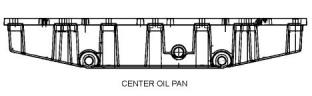
Refill Capacities
Center Oil Pan
30 L
(1)
These values are approximate capacities for the crankcase oil
sump which include the standard oil filters that are installed at
the factory. Engines with auxiliary oil filters will require additional
oil. Refer to the OEM specifications for the capacity of the auxili-
ary oil filter.
Refer to this Operation and Maintenance Manual,
“Fluid Recommendations” for information about the
fluids which are acceptable for this engine.
Lubricant Refill Capacity
The refill capacities for the engine crankcase reflect
the approximate capacity of the crankcase or sump
plus standard oil filters. Auxiliary oil filter systems will
require additional oil. Refer to the OEM specifications
for the capacity of the auxiliary oil filter.
Coolant Refill Capacity
To maintain the cooling system, the total cooling
system capacity must be known. The capacity of the
total cooling system will vary. The capacity will
depend on the size of the radiator (capacity). Table 3
should be completed by the customer for the
maintenance of the cooling system.
Table 3
Approximate Capacity of the Cooling System
Compartment or
System
Liters
Quarts
Total Cooling System
(1)
(1)
The total cooling system capacity includes the following compo-
nents:the engine block, the radiator and all coolant hoses and
lines.
Illustration 22
g02293575
Standard and deep oil pans
i06194716
Fluid Recommendations
General Coolant Information
NOTICE
Never add coolant to an overheated engine. Engine
damage could result. Allow the engine to cool first.
Illustration 23
g02289293
Center oil pan
NOTICE
If the engine is to be stored in, or shipped to an area
with below freezing temperatures, the cooling system
must be either protected to the lowest outside temper-
ature or drained completely to prevent damage.
This document has been printed from SPI2. NOT FOR RESALE


![]()
![]()
![]()
![]()
![]()

![]()
![]()
![]()
![]()
40
SEBU9072
Refill Capacities
Fluid Recommendations
For a water analysis, consult one of the following
NOTICE
Frequently check the specific gravity of the coolant for
proper freeze protection or for anti-boil protection.
sources:
• Local water utility company
• Agricultural agent
• Independent laboratory
Clean the cooling system for the following reasons:
• Contamination of the cooling system
• Overheating of the engine
Additives
Additives help to protect the metal surfaces of the
cooling system. A lack of coolant additives or
insufficient amounts of additives enable the following
conditions to occur:
• Foaming of the coolant
NOTICE
Never operate an engine without water temperature
regulators in the cooling system. Water temperature
regulators help to maintain the engine coolant at the
proper operating temperature. Cooling system prob-
• Corrosion
• Formation of mineral deposits
• Rust
lems
can
develop
without
water
temperature
regulators.
• Scale
Many engine failures are related to the cooling
system. The following problems are related to cooling
system failures: Overheating, leakage of the water
pump and plugged radiators or heat exchangers.
• Foaming of the coolant
Many additives are depleted during engine operation.
These additives must be replaced periodically.
These failures can be avoided with correct cooling
system maintenance. Cooling system maintenance is
as important as maintenance of the fuel system and
the lubrication system. Quality of the coolant is as
important as the quality of the fuel and the lubricating
oil.
Additives must be added at the correct concentration.
Over concentration of additives can cause the
inhibitors to drop out-of-solution. The deposits can
enable the following problems to occur:
• Formation of gel compounds
Coolant is normally composed of three elements:
Water, additives and glycol.
• Reduction of heat transfer
• Leakage of the water pump seal
• Plugging of radiators, coolers, and small passages
Water
Water is used in the cooling system in order to
transfer heat.
Glycol
Distilled water or deionized water is
recommended for use in engine cooling systems.
Glycol in the coolant helps to provide protection
against the following conditions:
DO NOT use the following types of water in cooling
systems: Hard water, softened water that has been
conditioned with salt and sea water.
• Boiling
• Freezing
If distilled water or deionized water is not available,
use water with the properties that are listed in Table 4
.
• Cavitation of the water pump
Table 4
For optimum performance, Perkins recommends a
1:1 mixture of a water/glycol solution.
Acceptable Water
Property
Maximum Limit
40 mg/L
Note: Use a mixture that will provide protection
against the lowest ambient temperature.
Chloride (Cl)
Note: 100 percent pure glycol will freeze at a
temperature of −13 °C (8.6 °F).
Sulfate (SO4)
Total Hardness
Total Solids
Acidity
100 mg/L
170 mg/L
340 mg/L
pH of 5.5 to 9.0
This document has been printed from SPI2. NOT FOR RESALE

![]()
![]()
![]()
![]()
![]()
SEBU9072
41
Refill Capacities
Fluid Recommendations
Most conventional antifreezes use ethylene glycol.
Propylene glycol may also be used. In a 1:1 mixture
with water, ethylene and propylene glycol provide
similar protection against freezing and boiling. Refer
to Table 5 and refer to table 6 .
NOTICE
Do not use a commercial coolant/antifreeze that only
meets the ASTM D3306 specification. This type of
coolant/antifreeze is made for light automotive
applications.
Table 5
Ethylene Glycol
Perkins recommends a 1:1 mixture of water and
glycol. This mixture of water and glycol will provide
optimum heavy-duty performance as an antifreeze.
This ratio may be increased to 1:2 water to glycol if
extra freezing protection is required.
Concentration
50 Percent
Freeze Protection
−36 °C (−33 °F)
60 Percent
−51 °C (−60 °F)
A mixture of SCA inhibitor and water is acceptable
but will not give the same level of corrosion, boiling
and, freezing protection as ELC. Perkins
recommends a 6 percent to 8 percent concentration
of SCA in those cooling systems. Distilled water or
deionized water is preferred. Standard required
ASTM D1384, D2570, and D4340
NOTICE
Do not use propylene glycol in concentrations that ex-
ceed 50 percent glycol because of the reduced heat
transfer capability of propylene glycol. Use ethylene
glycol in conditions that require additional protection
against boiling or freezing.
Table 7
Coolant Service Life
Table 6
Coolant Type
Service Life (1)
Propylene Glycol
6,000 Service Hours or Three
Years
Concentration
Freeze Protection
Perkins ELC
50 Percent
−29 °C (−20 °F)
Commercial Heavy-Duty Anti-
freeze that meets “ASTM
D6210”
3000 Service Hours or Two Year
To check the concentration of glycol in the coolant,
measure the specific gravity of the coolant.
Commercial SCA inhibitor and
Water
3000 Service Hours or One Year
Coolant Recommendations
(1)
Use the interval that occurs first. The cooling system must also
be flushed out at this time.
• ELC
• SCA
• ASTM
Extended Life Coolant
Supplement Coolant Additive
American Society for Testing and
ELC
Perkins provides ELC for use in the following
applications:
Materials
• Heavy-duty spark ignited gas engines
• Heavy-duty diesel engines
• Automotive applications
The following two coolants are used in Perkins
diesel engines:
Preferred – Perkins ELC
Acceptable – A commercial heavy-duty antifreeze
that meets “ASTM D6210” specifications
The anti-corrosion package for ELC is different from
the anti-corrosion package for other coolants. ELC is
an ethylene glycol base coolant. However, ELC
contains organic corrosion inhibitors and antifoam
agents with low amounts of nitrite. Perkins ELC has
been formulated with the correct amount of these
additives in order to provide superior corrosion
protection for all metals in engine cooling systems.
NOTICE
The 1200 and 2200 series industrial engines must
be operated with a 1:1 mixture of water and glycol.
This concentration allows the NOx reduction sys-
tem
temperatures.
to
operate
correctly
at
high
ambient
ELC is available in a premixed cooling solution with
distilled water. ELC is a 1:1 mixture. The Premixed
ELC provides freeze protection to −36 °C (−33 °F).
The Premixed ELC is recommended for the initial fill
of the cooling system. The Premixed ELC is also
recommended for topping off the cooling system.
Containers of several sizes are available. Consult
your Perkins distributor for the part numbers.
This document has been printed from SPI2. NOT FOR RESALE


![]()
![]()
![]()
![]()
![]()
![]()
![]()
![]()
![]()
![]()
42
SEBU9072
Refill Capacities
Fluid Recommendations
ELC Cooling System Maintenance
NOTICE
Care must be taken to ensure that all fluids are con-
tained during performance of inspection, mainte-
nance, testing, adjusting and the repair of the
product. Be prepared to collect the fluid with suitable
containers before opening any compartment or disas-
sembling any component containing fluids.
Correct additions to the Extended Life
Coolant
NOTICE
Use only Perkins products for pre-mixed or concen-
trated coolants.
Dispose of all fluids according to local regulations and
mandates.
Mixing Extended Life Coolant with other products re-
duces the Extended Life Coolant service life. Failure
to follow the recommendations can reduce cooling
system components life unless appropriate corrective
action is performed.
1. Drain the coolant into a suitable container.
2. Dispose of the coolant according to local
regulations.
In order to maintain the correct balance between the
antifreeze and the additives, you must maintain the
recommended concentration of ELC. Lowering the
proportion of antifreeze lowers the proportion of
additive. Lowering the ability of the coolant to protect
the system will form pitting, from cavitation, from
erosion, and from deposits.
3. Fill the cooling system with a 33 percent solution of
Perkins ELC and operate the engine, ensure that
the thermostat opens. Stop the engine and allow
the engine to cool. Drain the coolant.
Note: Use distilled or deionized water in the solution.
4. Again, fill the cooling system with a 33 percent
solution of Perkins ELC and operate the engine
ensure that the thermostat opens. Stop the engine
and allow to cool.
NOTICE
Do not use a conventional coolant to top-off a cooling
system that is filled with Extended Life Coolant (ELC).
Do not use standard supplemental coolant additive
(SCA).
5. Drain the drain the cooling system.
When using Perkins ELC, do not use standard SCA's
or SCA filters.
NOTICE
Incorrect or incomplete flushing of the cooling system
can result in damage to copper and other metal
components.
ELC Cooling System Cleaning
Note: If the cooling system is already using ELC,
cleaning agents are not required to be used at the
specified coolant change interval. Cleaning agents
are only required if the system has been
contaminated by the addition of some other type of
coolant or by cooling system damage.
6. Fill the cooling system with the Perkins Premixed
ELC. Operate the engine. Ensure that all coolant
valves open then stop the engine. When cool
check the coolant level.
ELC Cooling System Contamination
Clean water is the only cleaning agent that is required
when ELC is drained from the cooling system.
NOTICE
Before the cooling system is filled, the heater control
(if equipped) must be set to the HOT position. Refer
to the OEM in order to set the heater control. After the
cooling system is drained and the cooling system is
refilled, operate the engine until the coolant level
reaches the normal operating temperature and until
the coolant level stabilizes. As needed, add the
coolant mixture in order to fill the system to the
specified level.
Mixing ELC with other products reduces the effective-
ness of the ELC and shortens the ELC service life.
Use only Perkins Products for premixed or concen-
trate coolants. Failure to follow these recommenda-
tions
component life.
can result in shortened cooling system
ELC cooling systems can withstand contamination to
a maximum of 10 percent of conventional heavy-duty
antifreeze or SCA. If the contamination exceeds 10
percent of the total system capacity, perform ONE of
the following procedures:
Changing to Perkins ELC
To change from heavy-duty antifreeze to the Perkins
ELC, perform the following steps:
This document has been printed from SPI2. NOT FOR RESALE
![]()
![]()
![]()
![]()
![]()
![]()
![]()
![]()
![]()
![]()
![]()
SEBU9072
43
Refill Capacities
Fluid Recommendations
• Drain the cooling system into a suitable container.
Dispose of the coolant according to local
regulations. Flush the system with a 5 to 10
percent solution of Perkins ELC. Fill the system
with the Perkins ELC.
Table 8
Equation For Adding The SCATo The Heavy-Duty Coolant At
The Initial Fill
V × 0.045 = X
V is the total volume of the cooling system.
• Drain a portion of the cooling system into a
suitable container according to local regulations.
Then, fill the cooling system with premixed ELC.
This procedure should lower the contamination to
less than 10 percent.
X is the amount of SCA that is required.
Table 9 is an example for using the equation that is in
Table 8 .
Table 9
• Maintain the system as a conventional Heavy-Duty
Coolant. Treat the system with an SCA. Change
the coolant at the interval that is recommended for
the conventional Heavy-Duty Coolant.
Example Of The Equation For Adding The SCATo The Heavy-
Duty Coolant At The Initial Fill
Total Volume of the
Cooling System (V)
Multiplication
Factor
Amount of SCA
that is Required (X)
Commercial Heavy-Duty Antifreeze and
SCA
15 L (4 US gal)
× 0.045
0.7 L (24 oz)
Adding The SCA to The Heavy-Duty
Coolant For Maintenance
NOTICE
Commercial Heavy-Duty Coolant which contains
Amine as part of the corrosion protection system must
not be used.
Heavy-duty antifreeze of all types REQUIRE periodic
additions of an SCA.
Test the antifreeze periodically for the concentration
of SCA. For the interval, refer to the Operation and
Maintenance Manual, “Maintenance Interval
NOTICE
Never operate an engine without water temperature
regulators in the cooling system. Water temperature
regulators help to maintain the engine coolant at the
correct operating temperature. Cooling system prob-
Schedule” (Maintenance Section). Cooling System
Supplemental Coolant Additive (SCA) Test/Add.
Additions of SCA are based on the results of the test.
The size of the cooling system determines the
amount of SCA that is needed.
lems
regulators.
can
develop
without
water
temperature
Use the equation that is in Table 10 to determine the
amount of SCA that is required, if necessary:
Check the antifreeze (glycol concentration) in order to
ensure adequate protection against boiling or
freezing. Perkins recommends the use of a
refractometer for checking the glycol concentration. A
hydrometer should not be used.
Table 10
Equation For Adding The SCATo The Heavy-Duty Coolant For
Maintenance
Perkins engine cooling systems should be tested at
500 hour intervals for the concentration of SCA.
V × 0.014 = X
V is the total volume of the cooling system.
Additions of SCA are based on the results of the test.
An SCA that is liquid may be needed at 500 hour
intervals.
X is the amount of SCA that is required.
Table 11 is an example for using the equation that is
in Table 10 .
Adding the SCA to Heavy-Duty Coolant at
the Initial Fill
Table 11
Example Of The Equation For Adding The SCATo The Heavy-
Duty Coolant For Maintenance
Use the equation that is in Table 8 to determine the
amount of SCA that is required when the cooling
system is initially filled.
Total Volume of the
Cooling System (V)
Multiplication
Factor
Amount of SCA
that is Required (X)
15 L (4 US gal)
× 0.014
0.2 L (7 oz)
This document has been printed from SPI2. NOT FOR RESALE


![]()
![]()
![]()
![]()
![]()
44
SEBU9072
Refill Capacities
Fluid Recommendations
Cleaning the System of Heavy-Duty
Antifreeze
Table 12 provides a known reliable baseline in order
to judge the expected performance of distillate diesel
fuels that are derived from conventional sources.
• Clean the cooling system after used coolant is
drained or before the cooling system is filled with
new coolant.
Satisfactory engine performance is dependent on the
use of a good quality fuel. The use of a good quality
fuel will give the following results: long engine life and
acceptable exhaust emissions levels. The fuel must
meet the minimum requirements that are stated in
table 12 .
• Clean the cooling system whenever the coolant is
contaminated or whenever the coolant is foaming.
NOTICE
i06218481
Fluid Recommendations
(Fuel Recommendations)
The footnotes are a key part of the Perkins Specifica-
tion for Distillate Diesel Fuel Table. Read ALL of the
footnotes.
• Glossary
• ISO International Standards Organization
• ASTM American Society for Testing and Materials
• HFRR High Frequency Reciprocating Rig for
Lubricity testing of diesel fuels
• FAME Fatty Acid Methyl Esters
• CFRCo-ordinating Fuel Research
• LSD Low Sulfur Diesel
• ULSD Ultra Low Sulfur Diesel
• RMERape Methyl Ester
• SME Soy Methyl Ester
• EPA Environmental Protection Agency of the
United States
General Information
NOTICE
Every attempt is made to provide accurate, up-to-date
information. By use of this document you agree that
Perkins Engines Company Limited is not responsible
for errors or omissions.
NOTICE
These recommendations are subject to change with-
out notice. Contact your local Perkins distributor for
the most up-to-date recommendations.
Diesel Fuel Requirements
Perkins is not in a position to evaluate continuously
and monitor all worldwide distillate diesel fuel
specifications that are published by governments and
technological societies.
This document has been printed from SPI2. NOT FOR RESALE
![]()
![]()
![]()
![]()
![]()
![]()
![]()
SEBU9072
45
Refill Capacities
Fluid Recommendations
Table 12
Perkins Specification for Distillate Diesel Fuel
Property
UNITS
Requirements
“ASTM Test”
“ISO Test”
Aromatics
Ash
%Volume
%Weight
35% maximum
“D1319”
“D482”
“ISO 3837”
“ISO 6245”
0.01% maximum
Carbon Residue on 10%
Bottoms
%Weight
0.35% maximum
“D524”
“ISO 4262”
Cetane Number (1)
Cloud Point
-
40 minimum
“D613 or D6890”
“D2500”
“ISO 5165”
“ISO 3015”
°C
The cloud point must not ex-
ceed the lowest expected
ambient temperature.
Copper Strip Corrosion
Distillation
-
No. 3 maximum
“D130”
“D86”
“ISO 2160”
“ISO 3405”
°C
10% at 282 °C (539.6 °F)
maximum
90% at 360 °C (680 °F)
maximum
Density at 15 °C (59 °F)(2) Kg / M
3
800 minimum and 860
maximum
No equivalent test
“ISO 3675” or “ISO 12185”
Flash Point
°C
-
legal limit
“D93”
“ISO 2719”
Thermal Stability
Minimum of 80% reflectance
after aging for 180 minutes
at 150 °C (302 °F)
“D6468”
No equivalent test
Pour Point
°C
6 °C (10°F)
“D97”
“ISO 3016”
Minimum below ambient
temperature
Sulfur
%mass
(3)
“D5453 or /D26222”
“D445”
“ISO 20846” or “ISO 20884”
“ISO 3405”
Kinematic Viscosity (4)
2
“MM /S (cSt)”
The viscosity of the fuel that
is delivered to the fuel injec-
tion pump. “1.4 minimum
and /4.5 maximum”
Water and sediment
Water
% weight
% weight
% weight
mg/100mL
mm
0.05% maximum
“D1796”
“D1744”
“D473”
“D381”
“D6079”
“ISO 3734”
0.05% maximum
No equivalent test
“ISO 3735”
Sediment
0.05% maximum
Gums and Resins(5)
10 mg per 100 mL maximum
0.46 maximum
“ISO 6246”
Lubricity corrected wear
“ISO 12156-1”
scar diameter at 60 °C
(140 °F). (6)
Fuel cleanliness (7)
-
“ISO”18/16/13
“7619”
“ISO 4406”
(1)
In order to insure minimum cetane number of 40 a distillate diesel fuel should have minimum cetane index of 44 when ASTM D4737 test meth-
od is used. A fuel with a higher cetane number is recommended in order to operate at a higher altitude or in cold weather.
Density range allowed includes summer and winter diesel fuel grades. Fuel density varies depending on the sulfur level where high sulfur fuels
have higher densities. Some unblended alternative fuels have lower densities which are acceptable, if all the other properties meet this
specification.
(2)
(3)
Regional regulations, national regulations, or international regulations can require a fuel with a specific sulfur limit. Consult all applicable regu-
lations before selecting a fuel for a given engine application. LSD fuel with less than 0.05 percent (≤ 500 ppm (mg/kg)) sulfur is strongly recom-
mended for use in these engine models. Diesel fuel with more than 0.05 percent (≥ 500 ppm (mg/kg)) sulphur can be used only where allowed
by legislation. Fuel sulfur levels affect exhaust emissions. High sulfur fuels also increase the potential for corrosion of internal components.
Fuel sulfur levels above 0.05% may significantly shorten the oil change interval. For additional information, refer to General lubricant
Information.
(continued)
This document has been printed from SPI2. NOT FOR RESALE

![]()
46
SEBU9072
Refill Capacities
Fluid Recommendations
(Table 12, contd)
(4)
The values of the fuel viscosity are the values as the fuel is delivered to the fuel injection pumps. Fuel should also meet the minimum viscosity
requirementand the fuel should meet the maximum viscosity requirements at 40° C (104° F) of either the "ASTM D445" test method or the
"ISO 3104" test method. If a fuel with a low viscosity is used, cooling of the fuel may be required to maintain 1.4 cSt or great, er viscosity at the
fuel injection pump. Fuels with a high viscosity might require fuel heaters in order to lower the viscosity to 4.5 cSt at the fuel injection pump.
Follow the test conditions and procedures for gasoline (motor).
The lubricity of a fuel is a concern with low sulfur and ultra low sulfur fuel. To determine the lubricity of the fuel, use the “ISO 12156-1 or ASTM
D6079 High Frequency Reciprocating Rig (HFRR)” test. If the lubricity of a fuel does not meet the minimum requirements, consult your fuel
supplier. Do not treat the fuel without consulting the fuel supplier. Some additives are not compatible. These additives can cause problems in
the fuel system.
(5)
(6)
(7)
Recommended cleanliness level for fuel as dispensed into machine or engine fuel tank is "ISO 18/16/13 or cleaner as per ISO 4406. Refer to
the "Contamination Control Recommendations for Fuels" in this chapter.
Viscosity
NOTICE
Operating with fuels that do not meet the Perkins rec-
ommendations can cause the following effects: Start-
ing difficulty, poor combustion, deposits in the fuel
injectors, reduced service life of the fuel system, de-
posits in the combustion chamber and reduced serv-
ice life of the engine.
Viscosity is the property of a liquid of offering
resistance to shear or flow. Viscosity decreases with
increasing temperature. This decrease in viscosity
follows a logarithmic relationship for normal fossil
fuel. The common reference is to kinematic viscosity.
Kinematic viscosity is the quotient of the dynamic
viscosity that is divided by the density. The
determination of kinematic viscosity is normally by
readings from gravity flow viscometers at standard
temperatures. Refer to “ISO 3104” for the test
method.
Engines that are manufactured by Perkins are certi-
fied with the fuel that is prescribed by the United
States Environmental Protection Agency. Engines
that are manufactured by Perkins are certified with
the fuel that is prescribed by the European Certifica-
tion and other regulatory agencies. Perkins does not
certify diesel engines on any other fuel.
The viscosity of the fuel is significant because fuel
serves as a lubricant for the fuel system components.
Fuel must have sufficient viscosity in order to
lubricate the fuel system in both cold temperatures
and hot temperatures. If the kinematic viscosity of the
fuel is lower than 1.4 cSt at the fuel injection pump,
damage to the fuel injection pump can occur. This
damage can be excessive scuffing and seizure. Low
viscosity may lead to difficult hot restarting, stalling,
and loss of performance. High viscosity may result in
seizure of the pump.
Note: The owner and the operator of the engine has
the responsibility of using the fuel that is prescribed
by the Environmental Protection Agency (EPA) and
other appropriate regulatory agencies.
Diesel Fuel Characteristics
Perkins Recommendations
Perkins recommends kinematic viscosities of 1.4 and
4.5 cSt that is delivered to the fuel injection pump. If a
fuel with a low viscosity is used, cooling of the fuel
may be required to maintain 1.4 cSt or greater
Cetane Number
Fuel that has a high cetane number will give a shorter
ignition delay. A high cetane number will produce a
better ignition quality. Cetane numbers are derived for
fuels against proportions of cetane and
viscosity at the fuel injection pump. Fuels with a high
viscosity might require fuel heaters in order to lower
the viscosity to 4.5 cSt at the fuel injection pump.
heptamethylnonane in the standard CFR engine.
Refer to “ISO 5165” for the test method.
Density
Cetane numbers in excess of 45 are normally
expected from current diesel fuel. However, a cetane
number of 40 may be experienced in some territories.
The United States of America is one of the territories
that can have a low cetane value. A minimum cetane
value of 40 is required during average starting
conditions. A higher cetane value may be required for
operations at high altitudes or in cold-weather
operations.
Density is the mass of the fuel per unit volume at a
specific temperature. This parameter has a direct
influence on engine performance and a direct
influence on emissions. This influence determines the
heat output from a given injected volume of fuel. This
parameter is quoted in the following kg/m3 at 15 °C
(59 °F).
Perkins recommends a value of density of 841 kg/m3
in order to obtain the correct power output. Lighter
fuels are acceptable but these fuels will not produce
the rated power.
Fuel with a low cetane number can be the root cause
of problems during cold start.
This document has been printed from SPI2. NOT FOR RESALE
![]()
![]()
![]()
SEBU9072
47
Refill Capacities
Fluid Recommendations
Sulfur
In case of the fuels which do not meet specified
lubricity requirement appropriate lubricity additive can
be used to enhance the lubricity of the fuel.
21820275 Perkins Diesel Fuel Conditioner is the
approved additive refer to “Perkins Diesel Fuel
Conditioner”.
The level of sulfur is governed by emissions
legislations. Regional regulation, national regulations,
or international regulations can require a fuel with a
specific sulfur limit. The sulfur content of the fuel and
the fuel quality must comply with all existing local
regulations for emissions.
Contact your fuel supplier for those circumstances
when fuel additives are required. Your fuel supplier
can make recommendations for additives to use and
for the proper level of treatment.
LSD fuel with less than 0.05 percent (≤ 500 ppm (mg/
kg)) sulfur is strongly recommended for use in these
engine models.
Distillation
ULSD less than 0.0015% (≤15 PPM (mg/Kg)) sulphur
is acceptable to use in these engine models. The
lubricity of these fuels must not exceed wear scar
diameter of 0.46 mm (0.01811 inch) as per “ISO
12156-1”. Refer to “Lubricity” for more information.
Distillation will give an indication of the mixture of
different hydrocarbons in the fuel. A high ratio of light
weight hydrocarbons can affect the characteristics of
combustion.
Fuels with sulphur content higher than 0.05 percent
(500 PPM) can be used where allowed by legislation.
Classificationof the Fuels
Diesel engines have an ability to burn wide variety of
fuels. Below is a list of typically encountered fuel
specifications that have been assessed as to their
acceptability and are divided into following
categories:
Fuel with a high sulfur content can cause engine
wear. High sulfur fuel will have a negative impact on
emissions of particulates. High sulfur fuel can be
used if the local emissions legislation will allow the
use. High sulfur fuel can be used in countries that do
not regulate emissions.
Group 1: Preferred Fuels
When only high sulfur fuels are available, it will be
necessary that high alkaline lubricating oil is used in
the engine or that the lubricating oil change interval is
reduced. Refer to Operation and Maintenance
Manual, “Fluid Recommendations (Lubricant
Information)”for information on sulfur in fuel.
The following fuel specifications are considered
acceptable.
• Fuels that meet the requirements that are listed in
the table 12 .
Lubricity
•
•
•
“EN590 - Grades A to F and class 0 to 4”
“ASTM D975 Grade No. 1-D and 2-D”
Lubricity is the capability of the fuel to prevent pump
wear. The lubricity of the fluid describes the ability of
the fluid to reduce the friction between surfaces that
are under load. This ability reduces the damage that
is caused by friction. Fuel injection systems rely on
the lubricating properties of the fuel. Until fuel sulfur
limits were mandated, the lubricity of the fuel was
believed to be a function of fuel viscosity.
“JIS K2204 Grades 1, 2 & 3 & Special Grade 3”
acceptable provided lubricity ware scar diameter
does not exceed of 0.46 mm (0.01811 inch) as per
“ISO 12156-1” .
•
“BS2869 - Class A2 Off Highway Gas Oil, Red
Diesel”
The lubricity has particular significance to the current
low viscosity fuel, low sulfur fuel, and low aromatic
fossil fuel. These fuels are made in order to meet
stringent exhaust emissions.
Note: The lubricity of these fuels must not exceed
wear scar diameter of 0.46 mm (0.01811 inch) as per
“ISO 12156-1” . Refer to “Lubricity”.
The lubricity of these fuels must not exceed wear scar
diameter of 0.46 mm (0.01811 inch). The fuel lubricity
test must be performed on an HFRR, operated at
60 °C (140 °F). Refer to “ISO 12156-1”.
Group 2: Aviation Kerosene Fuels
Following kerosene and jet fuel specifications are
acceptable alternative fuels, and may be used on a
contingency base for emergency or continuous use,
where standard diesel fuel is not available and where
legislation allows their use:
NOTICE
The fuels system has been qualified with fuel having
lubricity up to 0.46 mm (0.01811 inch)wear scar di-
ameter as tested by “ISO 12156-1”. Fuel with higher
wear scar diameter than 0.46 mm (0.01811 inch) will
lead to reduced service life and premature failure of
the fuel system.
This document has been printed from SPI2. NOT FOR RESALE
![]()
![]()
![]()
48
SEBU9072
Refill Capacities
Fluid Recommendations
•
•
•
•
•
•
•
“MIL-DTL-83133 NATO F34 (JP-8)”
“MIL-DTL-83133 NATO F35”
“MIL-DTL-5624 NATO F44 (JP-5)”
“MIL-DTL-38219 (USAF) (JP7)”
“NATO XF63”
Raw pressed vegetable oils are NOTacceptable for
use as a fuel in any concentration in compression
engines. Without esterification, these oils may gel in
the crankcase and the fuel tank. These fuels may not
be compatible with many of the elastomers that are
used in engines that are manufactured today. In
original forms, these oils are not suitable for use as a
fuel in compression engines. Alternate base stocks
for biodiesel may include animal tallow, waste
cooking oils, or various other feedstocks. In order to
use any of the products that are listed as fuel, the oil
must be esterified.
“ASTM D1655 JETA”
“ASTM D1655 JETA1”
Fuel made of 100 percent FAME is generally referred
to as B100 biodiesel or neat biodiesel.
NOTICE
These fuels are only acceptable when used with ap-
propriate lubricity additive and must meet minimum
requirements that are listed in table 12 . The lubricity
of these fuels must not exceed wear scar diameter of
0.46 mm (0.01811 inch) as per “ISO 12156-1” . Refer
to “Lubricity” and Perkins Diesel Fuel Conditioner.
Biodiesel can be blended with distillate diesel fuel.
The blends can be used as fuel. The most commonly
available biodiesel blends are B5, which is 5 percent
biodiesel and 95 percent distillate diesel fuel. B20,
which is 20 percent biodiesel and 80 percent distillate
diesel fuel.
Note: The percentages given are volume-based. The
U.S. distillate diesel fuel specification “ASTM D975-
09a” includes up to B5 (5 percent) biodiesel.
Note: Minimum cetane number of 40 is
recommended otherwise cold starting problems or
light load misfire might occur. Since jet fuel
specifications do not mention cetane requirements,
Perkins recommends that a fuel sample is taken to
determine the cetane number.
European distillate diesel fuel specification
“EN590:2010” includes up B7 (7 percent) biodiesel.
Note: Engines that are manufactured by Perkins are
certified by use of the prescribed Environmental
Protection Agency (EPA) and European Certification
fuels. Perkins does not certify engines on any other
fuel. The user of the engine has the responsibility of
using the correct fuel that is recommended by the
manufacturer and allowed by the EPA and other
appropriate regulatory agencies.
Note: Fuels must have minimum viscosity of 1.4 cSt
delivered to the fuel injection pump. Cooling of the
fuel may be required to maintain 1.4 cSt or greater
viscosity at the fuel injection pump. Perkins
recommends that the actual viscosity of the fuel, be
measured in order to determine if a fuel cooler is
needed. Refer to “Viscosity”.
Note: Rated power loss of up to 10 percent is
possible due to lower density and lower viscosity of
jet fuels compared to diesel fuels.
SpecificationRequirements
The neat biodiesel must conform to “EN14214” or
“ASTM D6751” (in the USA) and can only be blended
in mixture of up to 20 percent, by volume in
acceptable mineral diesel fuel meeting requirements
that are listed in table 12 or the latest edition of
“EN590” and “ASTM D 975” commercial standards.
This blend is commonly known as B20.
Biodiesel Fuel
Biodiesel is a fuel that can be defined as mono-alkyl
esters of fatty acids. Biodiesel is a fuel that can be
made from various feedstock. The most commonly
available biodiesel in Europe is Rape Methyl Ester
(REM). This biodiesel is derived from rapeseed oil.
Soy Methyl Ester (SME) is the most common
biodiesel in the United States. This biodiesel is
derived from soybean oil. Soybean oil or rapeseed oil
are the primary feedstocks. These fuels are together
known as Fatty Acid Methyl Esters (FAME).
Biodiesel blends are denoted as “BXX” with “XX”
representing the content of neat biodiesel contained
in the blend with mineral diesel fuel (for example B5,
B10, B20).
In United States Biodiesel blends of B6 to B20 must
meet the requirements listed in the latest edition of
“ASTM D7467” (B6 to B20) and must be of an API
gravity of 30-45.
In North America biodiesel and biodiesel blends must
be purchased from the BQ-9000 accredited
producers and BQ-9000 certified distributors.
This document has been printed from SPI2. NOT FOR RESALE
![]()
![]()
![]()
SEBU9072
49
Refill Capacities
Fluid Recommendations
In other areas of the world, the use of biodiesel that is
BQ-9000 accredited and certified, or that is
accredited and certified by a comparable biodiesel
quality body to meet similar biodiesel quality
standards is required.
Perkins T400012 Fuel Cleaner is most effective in
cleaning and preventing the formation of deposits.
Refer to “Perkins Diesel Fuel System Cleaner” for
more information. Perkins UMK8276 Diesel Fuel
Conditioner helps to limit deposit issues by improving
the stability of biodiesel while also hindering the
production of new deposits. For more information
refer to “Perkins Diesel Fuel Conditioner”. Therefore
the use of Diesel Fuel Cleaner and or Diesel Fuel
Conditioner is strongly recommended when running
biodiesel blends, especially B20.
Engine Service Requirements with B20
Aggressive properties of biodiesel fuel may cause
debris in the fuel tank and fuel lines. The aggressive
properties of biodiesel will clean the fuel tank and fuel
lines. This cleaning of the fuel system can
prematurely block of the fuel filters. Perkins
recommends that after the initial usage of B20
biodiesel blended fuel the fuel filters must be replaced
at 50 hours.
General Requirements
Biodiesel has poor oxidation stability, which can result
in long-term problems in the storage of biodiesel.
Biodiesel fuel should be used within 6 months of
manufacture. Equipment should not be stored with
the B20 biodiesel blends in the fuel system for longer
than 3 months.
Glycerides present in biodiesel fuel will also cause
fuel filters to become blocked more quickly. Therefore
the regular service interval should be reduced to 250
hours.
Due to poor oxidation stability and other potential
issues, Perkins strongly recommends that engines
with limited operational time either do not use
biodiesel blends or, while accepting some risk, limit
biodiesel blend to a maximum of B5. Examples of
applications that should limit the use of biodiesel are
the following: Standby generator sets and certain
emergency vehicles.
When biodiesel fuel is used, crank case oil and
aftertreatmentsystems (if installed) may be
influenced. This influence is due to the chemical
composition and characteristics of biodiesel fuel,
such as density and volatility, and to chemical
contaminants that can be present in this fuel, such as
alkali and alkaline metals (sodium, potassium,
calcium, and magnesium).
If biodiesel must be used, then the quality of the fuel
needs to be periodically tested. The test must comply
with “EN15751”, commonly known as the Rancimat
Test.
• Crankcase oil fuel dilution can be higher when
biodiesel or biodiesel blends are used. This
increased level of fuel dilution when using
biodiesel or biodiesel blends is related to the
typically lower volatility of biodiesel. In cylinder
emissions control strategies utilized in many of the
industrial latest engine designs may lead to a
higher level of biodiesel concentration in the
engine oil pan. The long-term effect of biodiesel
concentration in crankcase oil is currently
unknown.
Perkins strongly recommends that seasonally
operated engines have the fuel systems, including
fuel tanks, flashed with conventional diesel fuel
before prolonged shutdown periods. An example of
an application that should seasonally flush the fuel
system is a combine harvester.
Microbial contamination and growth can cause
corrosion in the fuel system and premature plugging
of the fuel filter. Consult your supplier of fuel for
assistance in selecting appropriate antimicrobial
additive.
• Perkins recommends the use of oil analysis in
order to check the quality of the engine oil if
biodiesel fuel is used. Ensure that the level of
biodiesel in the fuel is noted when the oil sample is
taken.
Water accelerates microbial contamination and
growth. When biodiesel is compared to distillate fuels,
water is naturally more likely to exist in the biodiesel.
It is therefore essential to check frequently and if
necessary, drain the water separator.
Performance Related Issues with B20
Due to the lower energy content than the standard
distillate fuel B20 will cause a power loss in order of 2
to 4 percent. In addition, over time the power may
deteriorate further due to deposits in the fuel injectors.
Materials such as brass, bronze, copper, led, tin, and
zinc accelerate the oxidation process of the biodiesel
fuel. The oxidation process can cause deposits
formation therefore these materials must not be used
for fuel tanks and fuel lines.
Biodiesel and biodiesel blends are known to cause an
increase in fuel system deposits, most significant of
which are deposits within the fuel injector. These
deposits can cause a loss in power due to restricted
or modified fuel injection or cause other functional
issues associated with these deposits.
This document has been printed from SPI2. NOT FOR RESALE
![]()
50
SEBU9072
Refill Capacities
Fluid Recommendations
Fuel for Cold Weather Operation
Supplemental diesel fuel additives are not
recommended and is due to potential damage to the
fuel system or the engine. Your fuel supplier or the
fuel manufacturer will add the appropriate
supplemental diesel fuel additives.
The European standard “EN590” contains climate
dependant requirements and a range of options. The
options can be applied differently in each country.
There are five classes that are given to arctic climates
and severe winter climates. 0, 1, 2, 3 and 4.
Perkins recognizes the fact that additives may be
required in some special circumstances. Fuel
additives need to be used with caution. Contact your
fuel supplier for those circumstances when fuel
additives are required. Your fuel supplier can
recommend the appropriate fuel additive and the
correct level of treatment.
Fuel that complies with “EN590” CLASS 4 can be
used at temperatures as low as −44 °C (−47.2 °F).
Refer to “EN590” for a detailed discretion of the
physical properties of the fuel.
The diesel fuel “ASTM D975 1-D” that is used in the
United States of America may be used in cold
temperatures that are below −18 °C (−0.4 °F).
Note: For the best results, your fuel supplier should
treat the fuel when additives are required. The treated
fuel must meet the requirements that are stated in
table 12 .
In extreme cold ambient conditions, you may use the
aviation kerosene fuels that are specified in “Group 1:
Preferred Fuels”. These fuels are intended to be used
in temperatures that can be as low as −54 °C
(−65.2 °F). Refer to “Group 1: Preferred Fuels” for
detail and conditions of use of the aviation kerosene
fuels.
Perkins Diesel Fuel System Cleaner
Perkins T400012 Fuel Cleaner is the only fuel
cleaner that is recommended by Perkins .
If biodiesel or biodiesel blends of fuel are to be used,
Perkins require the use of Perkins fuel cleaner. For
more information on the use of biodiesel and
biodiesel blends refer to “Biodiesel Fuel”.
Mixing alcohol or gasoline with diesel fuel can
produce an explosive mixture in the engine crank-
case or the fuel tank. Alcohol or gasoline must
not be used in order to dilute diesel fuel. Failure
to follow this instruction may result in death or
personal injury.
Perkins fuel cleaner will remove deposits that can
form in the fuel system with the use of biodiesel and
biodiesel blends. These deposits can create a loss of
power and engine performance.
Once the fuel cleaner has been added to the fuel, the
deposits within the fuel system are removed after 30
hours of engine operation. For maximum results,
continue to use the fuel cleaner for up to 80 hours.
Perkins fuel cleaner can be used on an on-going
basis with no adverse impact on engine or fuel
system durability.
There are many other diesel fuel specifications that
are published by governments and by technological
societies. Usually, those specifications do not review
all the requirements that are addressed in table 12 .
To ensure optimum engine performance, a complete
fuel analysis should be obtained before engine
operation. The fuel analysis should include all of the
properties that are stated in the table 12 .
Detailed instructions on the rate of which the fuel
cleaner must be use are on the container.
Aftermarket Fuel Additives
Perkins Diesel Fuel Conditioner
The Perkins Diesel Fuel Conditioner part number
21820275/(U5MK8276) is the only fuel conditioner
recommended by Perkins. The diesel fuel conditioner
is a proprietary metal and ash free formulation that
has been extensively tested for use with distillate
diesel fuels for use in Perkins diesel engines. The
diesel fuel conditioner helps address many of the
challenges that various fuels worldwide present in
regards to fuel life/stability, engine startability, injector
deposits, fuel system life, and long-term engine
performance.
NOTICE
Perkins does not warrant the quality or performance
of non-Perkins fluids and filters.
When auxiliary devices, accessories, or consumables
(filters, additives) which are made by other manufac-
turers are used on Perkins products, the Perkins
warranty is not affected simply because of such use.
However, failures that result from the installation
or use of other manufacturers devices, accesso-
ries, or consumables are NOT Perkins
defects.
Therefore, the defects are NOT covered under the
Perkins warranty.
Note: Diesel fuel additives/conditioners may not
improve markedly poor diesel fuel properties enough
to make poor diesel acceptable for use.
This document has been printed from SPI2. NOT FOR RESALE
![]()
![]()
![]()
![]()
![]()
SEBU9072
51
Refill Capacities
Fluid Recommendations
Diesel fuel conditioner is a proven high performance,
multipurpose diesel fuel conditioner that is designed
to improve:
• Use high-quality fuels per recommended and
required specifications
• Fill fuel tanks with fuels of “ISO 18/16/13”
cleanliness level or cleaner, in particular for
engines with common rail and unit injection
systems. When you refuel the tank, filter the fuel
through a 4 µm absolute filter (Beta 4 = 75 up to
200) in order to reach the recommended
• Fuel economy (through fuel system cleanup)
• Lubricity
• Oxidation stability
cleanliness level. This filtration should be located
at the device that dispenses the fuel to the fuel
tank. In addition, filtration at the dispensing point
should remove water to ensure that fuel is
dispensed at 500 ppm water or less.
• Detergency/dispersancy
• Moisture dispersancy
• Corrosion protection
• Cetane (typically 2-3 cetane numbers)
• Perkins recommends the use of bulk fuel filter /
coalescer units which clean the fuel of both
particulate contamination and water in a single
pass.
The diesel fuel conditioner also reduces the formation
of gums, resins, and sludge, and disperses insoluble
gums.
• Ensure that you use Perkins Advanced Efficiency
Fuel Filters . Change your fuel filters per
recommended service requirements or as needed.
For maximum overall benefits, ask your fuel supplier
to add the fuel conditioner at the recommended treat
rate before fuel delivery. Or you may add the fuel
conditioner at the recommended treat rate during the
early weeks of fuel storage.
• Drain your water separators daily.
ContaminationControl
Recommendationsfor Fuels
• Drain your fuel tanks of sediment and water per
the Operation and Maintenance Manual
instructions.
Fuels of “ISO 18/16/13” cleanliness level or cleaner
as dispensed into the engine or application fuel tank
should be used. Reduce power loss, fuel system
failures, and related down time of engines will result.
This cleanliness level is important for new fuel system
designs such as common rail injection systems and
unit injection systems. Injection system designs utilize
higher fuel pressures and tight clearances between
moving parts in order to meet required stringent
emissions regulations. Peak injection pressures in
current fuel injection systems may exceed 30,000 psi.
Clearances in these systems are less than 5 µm. As a
result, particle contaminants as small as 4 µm can
cause scoring and scratching of internal pump and
injector surfaces and of injector nozzles.
• Install and maintain a properly designed bulk filter /
coalescer filtration system. Continuous bulk
filtration systems may be required to ensure that
dispensed fuel meets the cleanliness target.
Consult your Perkins distributor for availability of
bulk filtration products.
• Centrifugal filters may need to be used as a pre-
filter with fuel that is severely contaminated with
gross amounts of water and/or large particulate
contaminants. Centrifugal filters can effectively
remove large contaminants. Centrifugal filters may
not be able to remove the small abrasive particles
required to achieve the recommended “ISO”
cleanliness level. Bulk filter / coalescers are
necessary as a final filter in order to achieve the
recommended cleanliness level.
Water in the fuel causes cavitation, corrosion of fuel
system parts, and provides an environment where
microbial growth in the fuel can flourish. Other
sources of fuel contamination are soaps, gels, or
other compounds that may result from undesirable
chemical interactions in the fuels, particularly in
ULSD. Gels and other compounds can also form in
biodiesel fuel at low temperatures or if biodiesel is
stored for extended periods. The best indication of
microbial contamination, fuel additives, or cold
temperature gel is rapid filter plugging of bulk fuel
filters or application fuel filters.
• Install desiccant type breathers of 4 µm or less
absolute efficiency with the ability to remove water
on bulk storage tanks.
• Follow proper practices of fuel transportation.
Filtration from the storage tank to the application
promotes the delivery of clean fuel. Fuel filtration
can be installed at each transport stage in order to
keep the fuel clean.
In order to reduce downtime due to contamination,
follow these fuel maintenance guidelines.
• Cover, protect, and ensure cleanliness of all
connection hoses, fittings, and dispensing nozzles.
This document has been printed from SPI2. NOT FOR RESALE
![]()
52
SEBU9072
Refill Capacities
Fluid Recommendations
Consult your local Perkins distributor for additional
information on Perkins designed and produced
filtration products.
Engine Oil
Commercial Oils
i06110858
NOTICE
Fluid Recommendations
Perkins require the use of the following specifica-
tion of engine oil. Failure to use the appropriate
specification of engine oil will reduce the life of
your engine.
General Lubricant Information
Table 13
Because of government regulations regarding the
certification of exhaust emissions from the engine, the
lubricant recommendations must be followed.
Oil Specification
Preferred Oil Specification
Acceptable
• API
American Petroleum Institute
API CI-4 Plus
API CI-4
• SAE
Society Of Automotive Engineers Inc.
API CI-4 Plus meets the designed life of the product,
the use of the appropriate engine oil is essential.
Licensing
API CI-4 Plus provide two design improvements over
API CI-4 oil specification, soot viscosity control and
product shear stability.
The Engine Oil Licensing and Certification System by
the American Petroleum Institute (API). For detailed
information about this system, see the latest edition of
the “API publication No. 1509”. Engine oils that bear
the API symbol are authorized by API.
Maintenance intervals for engines that use
biodiesel – The oil change interval can be adversely
affected by the use of biodiesel. Use oil analysis in
order to monitor the condition of the engine oil. Use
oil analysis also in order to determine the oil change
interval that is optimum.
Note: These engine oils are not approved by
Perkins and these engine oils must not be used:
CC, CD, CD-2, CF-4, CG-4 and CH-4.
Lubricant Viscosity Recommendations
for Direct Injection (DI) Diesel Engines
The correct SAE viscosity grade of oil is determined
by the minimum ambient temperature during cold
engine start-up, and the maximum ambient
temperature during engine operation.
Illustration 24
g03813274
Typical API symbol
Refer to illustration 25 (minimum temperature) in
order to determine the required oil viscosity for
starting a cold engine.
Terminology
Certain abbreviations follow the nomenclature of
“SAE J754”. Some classifications follow “SAE J183”
abbreviations, and some classifications follow the
“EMA Recommended Guideline on Diesel Engine
Oil”. In addition to Perkins definitions, there are other
definitions that will be of assistance in purchasing
lubricants. Recommended oil viscosities can be
found in this publication, “Fluid Recommendations/
Engine Oil” topic (Maintenance Section).
Refer to illustration 25 (maximum temperature) in
order to select the oil viscosity for engine operation at
the highest ambient temperature that is anticipated.
Generally, use the highest oil viscosity that is
available to meet the requirement for the temperature
at start-up.
This document has been printed from SPI2. NOT FOR RESALE

![]()
![]()
![]()
![]()
![]()

![]()
![]()
SEBU9072
53
Refill Capacities
Fluid Recommendations
• See the appropriate “Lubricant Viscosities”. Refer
to the illustration 25 in order to find the correct oil
viscosity grade for your engine.
• At the specified interval, service the engine. Use
new oil and install a new oil filter.
• Perform maintenance at the intervals that are
specified in the Operation and Maintenance
Manual, “Maintenance Interval Schedule”.
Oil analysis
Some engines may be equipped with an oil sampling
valve. If oil analysis is required, the oil sampling valve
is used to obtain samples of the engine oil. The oil
analysis will complement the preventive maintenance
program.
The oil analysis is a diagnostic tool that is used to
determine oil performance and component wear
rates. Contamination can be identified and measured
by using oil analysis. The oil analysis includes the
following tests:
Illustration 25
g03329707
Lubricant Viscosities
• The Wear Rate Analysis monitors the wear of the
engines metals. The amount of wear metal and
type of wear metal that is in the oil is analyzed. The
increase in the rate of engine wear metal in the oil
is as important as the quantity of engine wear
metal in the oil.
Supplemental heat is recommended for cold soaked
starts below the minimum ambient temperature.
Supplemental heat may be required for cold soaked
starts that are above the minimum temperature that is
stated, depending on the parasitic load and other
factors. Cold soaked starts occur when the engine
has not been operated for a period of time. This
interval will allow the oil to become more viscous due
to cooler ambient temperatures.
• Tests are conducted in order to detect
contamination of the oil by water, glycol, or fuel.
Aftermarket Oil Additives
• The Oil Condition Analysis determines the loss of
the oils lubricating properties. An infrared analysis
is used to compare the properties of new oil to the
properties of the used oil sample. This analysis
allows technicians to determine the amount of
deterioration of the oil during use. This analysis
also allows technicians to verify the performance
of the oil according to the specification during the
entire oil change interval.
Perkins does not recommend the use of aftermarket
additives in oil. The use of aftermarket additives in
order to achieve the engines maximum service life or
rated performance is not necessary. Fully formulated,
finished oils consist of base oils and of commercial
additive packages. These additive packages are
blended into the base oils at precise percentages in
order to help provide finished oils with performance
characteristics that meet industry standards.
There are no industry standard tests that evaluate the
performance or the compatibility of aftermarket
additives in finished oil. Aftermarket additives may not
be compatible with the finished oils additive package,
which could lower the performance of the finished oil.
The aftermarket additive could fail to mix with the
finished oil. This failure could produce sludge in the
crankcase. Perkins discourages the use of
aftermarket additives in finished oils.
To achieve the best performance from a Perkins
engine, conform to the following guidelines:
This document has been printed from SPI2. NOT FOR RESALE
![]()
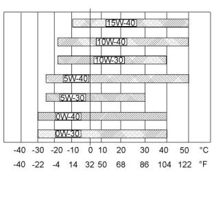
![]()
![]()
54
SEBU9072
Maintenance Recommendations
System Pressure Release
Maintenance
Recommendations
Do not loosen the high pressure fuel lines in order to
remove air pressure from the fuel system.
Engine Oil
i02909163
To relieve pressure from the lubricating system, turn
off the engine.
System Pressure Release
Coolant System
i05963859
Welding on Engines with
Electronic Controls
Pressurized system: Hot coolant can cause seri-
ous burn. To open cap, stop engine, wait until ra-
diator is cool. Then loosen cap slowly to relieve
the pressure.
NOTICE
Because the strength of the frame may decrease,
some manufacturers do not recommend welding onto
a chassis frame or rail. Consult the OEM of the equip-
ment or your Perkins distributor regarding welding on
a chassis frame or rail.
To relieve the pressure from the coolant system, turn
off the engine. Allow the cooling system pressure cap
to cool. Remove the cooling system pressure cap
slowly in order to relieve pressure.
Proper welding procedures are necessary in order to
avoid damage to the engines ECM, sensors, and
associated components. When possible, remove the
component from the unit and then weld the
Fuel System
To relieve the pressure from the fuel system, turn off
the engine.
component. If removal of the component is not
possible, the following procedure must be followed
when you weld on a unit equipped with an Electronic
Engine. The following procedure is considered to be
the safest procedure to weld on a component. This
procedure should provide a minimum risk of damage
to electronic components.
High Pressure Fuel Lines (If Equipped)
NOTICE
Contact with high pressure fuel may cause fluid
penetration and burn hazards. High pressure fuel
spray may cause a fire hazard. Failure to follow
these inspection, maintenance and service in-
structions may cause personal injury or death.
Do not ground the welder to electrical components
such as the ECM or sensors. Improper grounding can
cause damage to the drive train bearings, hydraulic
components,
components.
electrical
components,
and
other
Clamp the ground cable from the welder to the com-
ponent that will be welded. Place the clamp as close
as possible to the weld. This will help reduce the pos-
sibility of damage.
The high pressure fuel lines are the fuel lines that are
between the high pressure fuel pump and the high
pressure fuel manifold and the fuel lines that are
between the fuel manifold and cylinder head. These
fuel lines are different from fuel lines on other fuel
systems.
Note: Perform the welding in areas that are free from
This is because of the following differences:
explosive hazards.
• The high pressure fuel lines are constantly
charged with high pressure.
1. Stop the engine. Turn the switched power to the
OFF position.
• The internal pressures of the high pressure fuel
lines are higher than other types of fuel system.
2. Ensure that the fuel supply to the engine is turned
off.
Before any service or repair is performed on the
engine fuel lines, perform the following tasks:
3. Disconnect the negative battery cable from the
battery. If a battery disconnect switch is provided,
open the switch.
1. Stop the engine.
2. Wait for ten minutes.
This document has been printed from SPI2. NOT FOR RESALE
![]()
![]()
![]()
![]()
![]()
![]()
![]()
![]()
![]()
SEBU9072
55
Maintenance Recommendations
Welding on Engines with Electronic Controls
4. Disconnect all electronic components from the
wiring harnesses. Include the following
components:
• Electronic components for the driven equipment
• ECM
• Sensors
• Electronically controlled valves
• Relays
NOTICE
Do not use electrical components (ECM or ECM sen-
sors) or electronic component grounding points for
grounding the welder.
Illustration 26
g01075639
Use the example above. The current flow from the
welder to the ground clamp of the welder will not
damage any associated components.
(1) Engine
(2) Welding electrode
(3) Keyswitch in the OFF position
(4) Battery disconnect switch in the open position
(5) Disconnected battery cables
(6) Battery
(7) Electrical/Electronic component
(8) Minimum distance between the component that is being welded
and any electrical/electronic component
(9) The component that is being welded
(10) Current path of the welder
(11) Ground clamp for the welder
5. Connect the welding ground cable directly to the
part that will be welded. Place the ground cable as
close as possible to the weld in order to reduce the
possibility of welding current damage to the
following components. Bearings, hydraulic
components, electrical components, and ground
straps.
Note: If electrical/electronic components are used as
a ground for the welder, or electrical/electronic
components are located between the welder ground
and the weld, current flow from the welder could
severely damage the component.
6. Protect the wiring harness from welding debris and
spatter.
This document has been printed from SPI2. NOT FOR RESALE