English
 Espaol
 Franais
 阿拉伯
阿拉伯 中文
中文 Deutsch
 Italiano
 Português
 日本
日本 韩国
韩国 български
 hrvatski
 esky
esky Dansk
Dansk Nederlands
 suomi
suomi Ελληνικ
 印度
印度 norsk
norsk Polski
 Roman
Roman русский
 Svenska
珀金斯Perkins2506-15发动机测试调整手册供应商,珀金斯Perkins2506-15发动机测试调整手册技术价格规格咨询服务,珀金斯Perkins2506-15发动机测试调整手册零配件供应,珀金斯Perkins2506-15发动机测试调整手册售后服务中心,珀金斯Perkins2506-15发动机测试调整手册,珀金斯Perkins2506-15发动机测试调整手册详细的技术参数,

珀金斯Perkins2506-15发动机测试调整手册
详细描述
Systems Operation
Testing and Adjusting
2506-15 Industrial Engine
M G A (Engine)
MGB (Engine)
M G D (Engine)
Remove the valve cover and look for broken
parts. Repair any broken parts or replace any
broken parts that are found. Inspect all wiring to
the solenoids. Look for loose connections. Also
look for frayed wires or broken wires. Ensure
that the connector for the unit injector solenoid
is properly connected. Perform a pull test on
each of the wires. Refer to Troubleshooting,
“Electrical Connectors - Inspect”. Inspect the posts
of the solenoid for arcing. If arcing or evidence
of arcing is found, remove the cap assembly.
Refer to Disassembly and Assembly, “Electronic
Unit Injector - Remove”. Clean the connecting
posts. Reinstall the cap assembly and tighten
the solenoid nuts to a torque of 2.5 ± 0.25 N·m
(22 ± 2 lb in). Refer to Disassembly and Assembly,
“Electronic Unit Injector - Install”.
i02551444
Finding Top Center Position
for No. 1 Piston
Table 5
Required Tools
Tool
A
Part Number
CH11148
Part Description
Engine turning tool
Timing pin
Qty
1
B
27610286
1
The No. 1 piston at top center (TC) on the
compression stroke is the starting point of all timing
procedures.
3. Check the valve lash setting for the cylinder of the
suspect unit injector. Refer to Systems Operation,
Testing and Adjusting, “Engine Valve Lash -
Inspect/Adjust”.
4. Ensure that the bolt that holds the unit injector is
tightened to the proper torque. If necessary, loosen
the bolt that holds the unit injector and tighten the
bolt to a torque of 55 ± 10 N·m (40.6 ± 7.4 lb ft).
5. Remove the suspect unit injector and check the
unit injector for signs of exposure to coolant. Refer
to Disassembly and Assembly, “Electronic Unit
Injector - Remove”. Exposure to coolant will cause
rust to form on the injector. If the unit injector
shows signs of exposure to coolant, remove the
injector sleeve and inspect the injector sleeve.
Refer to Disassembly and Assembly, “Electronic
Unit Injector Sleeve - Remove”. Replace the
injector sleeve if the injector sleeve is damaged.
Check the unit injector for an excessive brown
discoloration that extends beyond the injector tip. If
excessive discoloration is found, check the quality
of the fuel. Refer to Systems Operation, Testing
and Adjusting, “Fuel Quality - Test”. Replace the
seals on the injector and reinstall the injector.
Refer to Disassembly and Assembly, “Electronic
Unit Injector - Install”. Also refer to Disassembly
and Assembly, “Electronic Unit Injector Sleeve -
Install”.
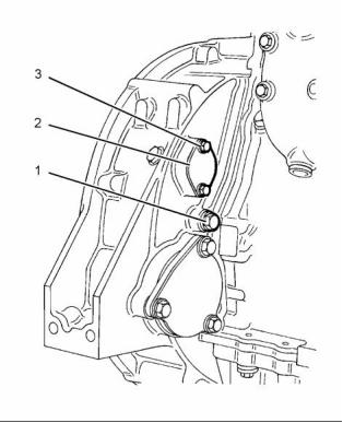
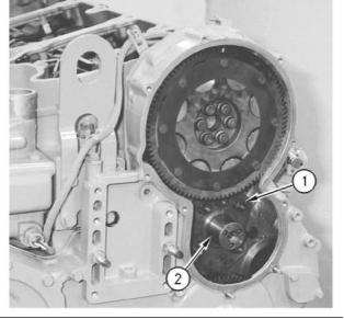
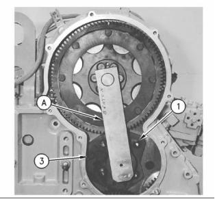
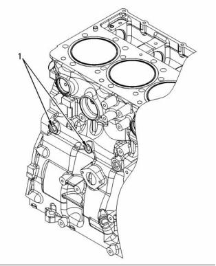
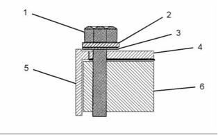
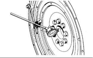
g01278981
Illustration 24
Typical example
6. If the problem is not resolved, replace the suspect
1. Remove both bolts (3) and cover (2) from the
flywheel housing. Remove the plug (1) from the
timing hole in the flywheel housing.
injector with a new injector.
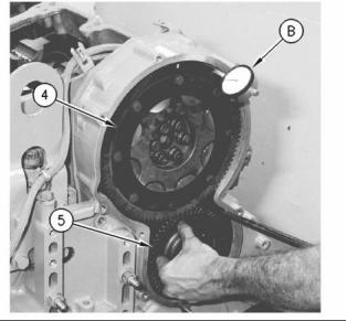
2. Install Tooling (A) into the flywheel housing
through the aperture behind the cover (2). Tooling
(A) is used in order to turn the engine flywheel in
the direction of normal engine rotation. Normal
engine rotation is counterclockwise. Normal
engine rotation is viewed from the flywheel end of
the engine. Turn the engine flywheel until Tooling
(B) engages with the threaded hole in the flywheel.
This document has been printed from SPI². Not for Resale
![]()
![]()
26
KENR6231
Testing and Adjusting Section
Note: If the flywheel is turned beyond the point
of engagement, the flywheel must be turned in
the opposite direction of normal engine rotation
approximately 45 degrees. Then turn the flywheel in
the direction of normal rotation until the timing bolt
engages with the threaded hole. The procedure will
eliminate the backlash that will occur when the No. 1
piston is put on the top center.
Refer to Operation and Maintenance Manual,
“Fuel Recommendations” for more information.
3. If fuel quality is still suspected as a possible
cause to problems regarding engine performance,
disconnect the fuel inlet line, and temporarily
operate the engine from a separate source of
fuel that is known to be good. This will determine
if the problem is caused by fuel quality. If fuel
quality is determined to be the problem, drain the
fuel system and replace the fuel filters. Engine
performance can be affected by the following
characteristics:
3. Remove the front valve mechanism cover from
the engine.
4. The inlet and exhaust valves for the No. 1 cylinder
are fully closed if the No. 1 piston is on the
compression stroke and the rocker arms can be
moved by hand. If the rocker arms can not be
moved and the valves are slightly open the No. 1
piston is on the exhaust stroke.
• Cetane number of the fuel
• Air in the fuel
• Other fuel characteristics
Note: After the actual stroke position is identified,
and the other stroke position is needed, remove the
timing bolt from the flywheel. The flywheel is turned
360 degrees in a counterclockwise direction. The
timing bolt is reinstalled.
i02551471
Fuel System - Prime
i02551477
NOTICE
Fuel Quality - Test
Use a suitable container to catch any fuel that might
spill. Clean up any spilled fuel immediately.
Ensure that all adjustments and repairs are performed
by authorized personnel that have had the correct
training.
NOTICE
Do not allow dirt to enter the fuel system. Thoroughly
clean the area around a fuel system component that
will be disconnected. Fit a suitable cover over discon-
nected fuel system component.
Use the following procedure to test for problems
regarding fuel quality:
Note: This procedure is most common when the
1. Determine if water and/or contaminants are
present in the fuel. Check the water separator (if
equipped). If a water separator is not present,
proceed to Step 2. Drain the water separator, if
necessary. A full fuel tank minimizes the potential
for overnight condensation.
engine has run out of fuel.
1. Turn the ignition switch to the “OFF” position.
2. Fill the fuel tank(s) with clean diesel fuel.
Note: A water separator can appear to be full of fuel
when the water separator is actually full of water.
2. Determine if contaminants are present in the
fuel. Remove a sample of fuel from the bottom
of the fuel tank. Visually inspect the fuel sample
for contaminants. The color of the fuel is not
necessarily an indication of fuel quality. However,
fuel that is black, brown, and/or similar to sludge
can be an indication of the growth of bacteria or
oil contamination. In cold temperatures, cloudy
fuel indicates that the fuel may not be suitable for
operating conditions.
This document has been printed from SPI². Not for Resale
![]()
![]()
![]()
![]()
![]()
KENR6231
27
Testing and Adjusting Section
• The engine starts, but the engine continues to
misfire or smoke.
9. Run the engine with no load until the engine runs
smoothly.
i02571703
Fuel System Pressure - Test
Low Fuel Pressure
Low fuel pressure can cause low power. Low fuel
pressure can also cause cavitation of the fuel
which can damage the fuel injectors. The following
conditions can cause low fuel pressure:
• Plugged fuel filters
• Debris in the check valves for the fuel priming
pump
• Debris in the pressure regulating valve
• Partially open check valve
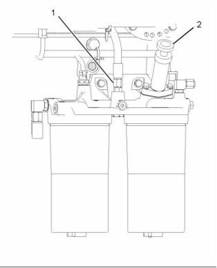
g01282239
Illustration 25
Typical example
• Sticking or worn fuel pressure regulating valve in
the fuel transfer pump
3. Loosen the union of the pipe for the fuel(1).
• Severe wear on return fuel pressure regulating
valve in the fuel filter base
Note: Do not remove the union completely. Open the
union enough to allow the air that is trapped in the
cylinder head to be purged from the fuel system.
• Worn gears in the fuel transfer pump
• Pinched fuel lines or undersized fuel lines
4. Unlock and operate the hand priming pump (2).
Use a suitable container to collect excess fuel.
• Old fuel lines that have a reduced interior diameter
that was caused by swelling
5. Tighten the union of the pipe for the fuel (1).
• Fuel lines with deteriorating interior surfaces
6. Operate the hand priming pump until a strong
pressure is felt on the pump. Push the priming
pump plunger inward. Tighten the plunger by hand
and start the engine.
• Pinched fuel line fittings or undersized fuel line
fittings
• Debris in the fuel tank, fuel lines, or fuel system
components that create restrictions
NOTICE
Do not crank the engine continuously for more than
30 seconds. Allow the starting motor to cool for 30
seconds before cranking the engine again.
High Fuel Pressure
Excessive fuel pressure can cause fuel filter gaskets
to rupture. The following conditions can cause high
fuel pressure:
7. If the engine will not start, allow the starting motor
to cool for 30 seconds. Repeat steps 3 to 6 in
order to operate the engine.
• Plugged orifices in the fuel pressure regulating
valve
8. Continue to eliminate air from the fuel system if
these events occur:
• Stuck fuel pressure regulating valve in the fuel
transfer pump
• The engine starts, but the engine does not run
evenly.
• Pinched fuel return line
This document has been printed from SPI². Not for Resale
![]()
![]()
![]()
![]()
28
KENR6231
Testing and Adjusting Section
Checking Fuel Pressure
i02551488
Gear Group (Front) - Time
Table 6
Required Tools
Tool
Part Number
Part Description
Qty
A
-
Pressure Gauge
1
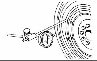
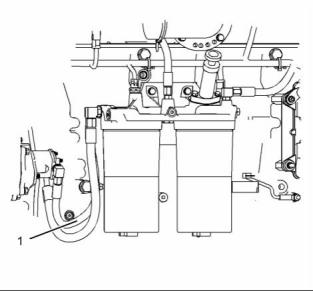
g01288627
Illustration 26
To check the fuel transfer pump pressure, remove
the hose assembly (1). Install a pressure gauge, and
start the engine.
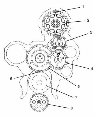
g01097754
Illustration 27
Front gear group
Fuel Pressure Readings
(1) Timing marks
(2) Camshaft gear
(3) Adjustable idler gear
(4) Idler gear
The typical fuel pressure of the engine at operating
temperature can vary. When the engine is under
load, the fuel pressure can be 550 kPa (80 psi).
(5) Cluster gear
(6) Timing marks
(7) Crankshaft gear
(8) Oil pump gear
The performance of the unit injector deteriorates
when the fuel pressure drops below 241 kPa (35 psi).
Low power complaints and erratic operation can
occur in this situation. Check for a plugged fuel filter
or air in the fuel lines as possible causes for these
complaints before replacing fuel system components.
The basis for the correct fuel injection timing and
the valve mechanism operation is determined by
the alignment of the timing for the front gear group.
Timing marks (1) through timing marks (6) are aligned
in order to provide the correct relationship between
the piston movement and the valve movement.
This document has been printed from SPI². Not for Resale
![]()

![]()
![]()
![]()
KENR6231
29
Testing and Adjusting Section
Setting Backlash For Camshaft
And Adjustable Idler Gear
Table 7
Required Tools
Tool
Part Number
Part Description
Qty
Camshaft Alignment
tool
A
27610321
1
21825617
Dial Indicator Group
Finger Clock
1
1
B
-
1. Remove the front cover. Refer to Disassembly and
Assembly, “Housing (front) - Remove”.
Note: Ensure that No. 1 piston is at the top center
position. Refer to Systems Operation, Testing and
Adjusting, “Finding Top Center Position for No. 1
Piston”.
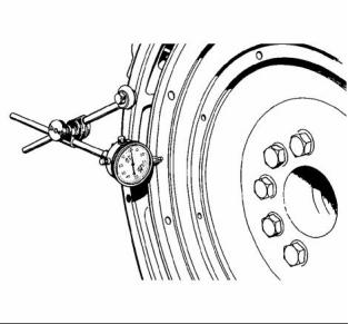
g00294873
Illustration 29
Typical example
Installation of the adjustable idler assembly
(A) Camshaft Alignment tool
(1) Nuts
(3) Bolt
3. Refer to Illustration 29 in order to position Tooling
(A). Move Tooling (A) to the left and to the right.
Lightly tighten nuts (1) and bolt (3). Once the nuts
and the bolt are tightened, lightly tap Tooling (A)
with a rubber mallet on the sides. This will ensure
that the tool is properly seated. Tooling (A) should
be free to move in and out without any binding.
g00294872
Illustration 28
Typical example
Loosen stub shaft assembly.
(1) Nuts
(2) Stub shaft
2. Remove the adjustable idler gear from stub shaft
(2). Stub shaft (2) is held in position with five nuts
(1) and one bolt. Loosen five nuts (1) and loosen
the one bolt.
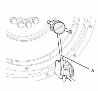
g00294874
Illustration 30
Typical example
Checking backlash
(B) Indicator assembly
(4) Camshaft gear
(5) Idler gear assembly
This document has been printed from SPI². Not for Resale
![]()
![]()
![]()
![]()
30
KENR6231
Testing and Adjusting Section
4. Install Tooling (B) on the timing gear housing.
Loosely install the idler gear assembly (5) to the
timing gear housing. When idler gear assembly
(5) is held stationary, the backlash between
the camshaft gear (4) and the idler gear (5) is
0.216 ± 0.114 mm (0.0085 ± 0.0045 inch).
5. If necessary, repeat step 2 through step 4 in order
to obtain the proper backlash.
6. Tighten the nuts and the bolt. Refer to Disassembly
and Assembly, “Gear Group (Front) - Install” for
the correct procedure.
7. Install the front cover. Refer to Disassembly and
Assembly, “Housing (Front) - Install”.
This document has been printed from SPI². Not for Resale
![]()
KENR6231
31
Testing and Adjusting Section
Air Inlet and Exhaust
System
i02581541
Air Inlet and Exhaust System
- Inspect
A general visual inspection should be made to the air
inlet and exhaust system. Make sure that there are
no signs of leaks in the system.
Table 8
Required Tools
Tool
Part Number
Part Description
Qty
Differential Pressure
Gauge
A
-
1
Air Inlet Restriction
There will be a reduction in the performance of the
engine if there is a restriction in the air inlet system.
1. Inspect the engine air cleaner inlet and ducting
in order to ensure that the passageway is not
blocked or collapsed.
2. Inspect the engine air cleaner element. Replace
a dirty engine air cleaner element with a clean
engine air cleaner element.
3. Check for dirt tracks on the clean side of the
engine air cleaner element. If dirt tracks are
observed, contaminants are flowing past the
engine air cleaner element and/or the seal for the
engine air cleaner element.
Hot engine components can cause injury from
burns. Before performing maintenance on the
engine, allow the engine and the components to
cool.
Making contact with a running engine can cause
burns from hot parts and can cause injury from
rotating parts.
When working on an engine that is running, avoid
contact with hot parts and rotating parts.
4. Use Tooling (A) for this test.
This document has been printed from SPI². Not for Resale
![]()

![]()
![]()
![]()
![]()
32
KENR6231
Testing and Adjusting Section
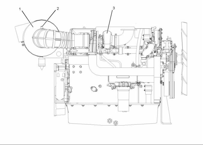
g01293044
Illustration 31
Air inlet piping
(1) Air Cleaner
(2) Test location
(3) Turbocharger
a. Connect the vacuum port of the differential
pressure gauge to test location (2). Test
location (2) may be located anywhere along the
air inlet piping after air cleaner (1) but before
turbocharger (3).
Maximum restriction ........ 6.2 kPa (25 in of H O)
2
The air flow through a new engine air cleaner element
must not have a restriction of more than the following
amount:
Maximum restriction ........ 3.7 kPa (15 in of H O)
2
b. Leave the pressure port of the differential
pressure gauge open to the atmosphere.
i02551491
c. Start the engine. Run the engine at full load.
d. Record the value.
Turbocharger - Inspect
e. Compare the result from step 4.d to the
appropriate values that follow.
The air flow through a used engine air cleaner
may have a restriction. The air flow through a
plugged engine air cleaner will be restricted to some
magnitude. In either case, the restriction must not be
more than the following amount:
Hot engine components can cause injury from
burns. Before performing maintenance on the
engine, allow the engine and the components to
cool.
This document has been printed from SPI². Not for Resale
![]()
![]()
![]()
![]()
KENR6231
33
Testing and Adjusting Section
1. Inspect the compressor wheel for damage from a
foreign object. If there is damage, determine the
source of the foreign object. As required, clean
the inlet system and repair the intake system.
Replace the turbocharger. If there is no damage,
go to Step 3.
Personal injury can result from rotating and mov-
ing parts.
Stay clear of all rotating and moving parts.
2. Clean the compressor wheel and clean the
compressor housing if you find buildup of foreign
material. If there is no buildup of foreign material,
go to Step 3.
Never attempt adjustments while the machine is
moving or the engine is running unless otherwise
specified.
The machine must be parked on a level surface
and the engine stopped.
3. Turn the rotating assembly by hand. While you
turn the assembly, push the assembly sideways .
The assembly should turn freely. The compressor
wheel should not rub the compressor housing.
Replace the turbocharger if the compressor wheel
rubs the compressor wheel housing. If there is no
rubbing or scraping, go to Step 4.
NOTICE
Keep all parts clean from contaminants.
Contaminants may cause rapid wear and shortened
component life.
4. Inspect the compressor and the compressor
wheel housing for oil leakage. An oil leak from
the compressor may deposit oil in the aftercooler.
Drain and clean the aftercooler if you find oil in
the aftercooler.
NOTICE
Care must be taken to ensure that fluids are contained
during performance of inspection, maintenance, test-
ing, adjusting and repair of the product. Be prepared to
collect the fluid with suitable containers before open-
ing any compartment or disassembling any compo-
nent containing fluids.
a. Check the oil level in the crankcase. If the oil
level is too high, adjust the oil level.
b. Inspect the air cleaner element for restriction. If
Dispose of all fluids according to local regulations and
mandates.
restriction is found, correct the problem.
c. Inspect the engine crankcase breather. Clean
the engine crankcase breather or replace
the engine crankcase breather if the engine
crankcase breather is plugged.
Before you begin inspection of the turbocharger,
be sure that the inlet air restriction is within the
specifications for your engine. Be sure that the
exhaust system restriction is within the specifications
for your engine. Refer to Systems Operation, Testing
and Adjusting, “Air Inlet and Exhaust System -
Inspect”.
d. Remove the oil drain line for the turbocharger.
Inspect the drain opening. Inspect the oil drain
line. Inspect the area between the bearings of
the rotating assembly shaft. Look for oil sludge.
Inspect the oil drain hole for oil sludge. Inspect
the oil drain line for oil sludge in the drain
line. If necessary, clean the rotating assembly
shaft. If necessary, clean the oil drain hole. If
necessary, clean the oil drain line.
The condition of the turbocharger will have definite
effects on engine performance. Use the following
inspections and procedures to determine the
condition of the turbocharger.
• Inspection of the Compressor and the Compressor
Housing
e. If Steps 4.a through 4.d did not reveal the
source of the oil leakage, the turbocharger has
internal damage. Replace the turbocharger.
• Inspection of the Turbine Wheel and the Turbine
Housing
Inspection of the Turbine Wheel
and the Turbine Housing
Inspection of the Compressor and
the Compressor Housing
Remove the air piping from the turbine housing.
Remove air piping from the compressor inlet.
This document has been printed from SPI². Not for Resale
![]()
![]()
![]()
![]()
![]()
![]()
![]()
34
KENR6231
Testing and Adjusting Section
a. Remove the oil drain line for the turbocharger.
Inspect the drain opening. Inspect the area
between the bearings of the rotating assembly
shaft. Look for oil sludge. Inspect the oil drain
hole for oil sludge. Inspect the oil drain line
for oil sludge. If necessary, clean the rotating
assembly shaft. If necessary, clean the drain
opening. If necessary, clean the drain line.
b. If crankcase pressure is high, or if the oil drain
is restricted, pressure in the center housing
may be greater than the pressure of turbine
housing (1). Oil flow may be forced in the wrong
direction and the oil may not drain. Check the
crankcase pressure and correct any problems.
c. If the oil drain line is damaged, replace the oil
drain line.
d. Check the routing of the oil drain line. Eliminate
any sharp restrictive bends. Make sure that
the oil drain line is not too close to the engine
exhaust manifold.
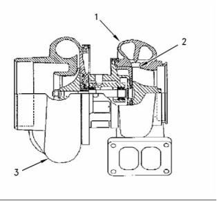
g00763164
Illustration 32
Typical example
(1) Turbine Housing
(2) Turbine Wheel
(3) Turbocharger
e. If Steps 4.a through 4.d did not reveal the
source of the oil leakage, turbocharger (3) has
internal damage. Replace turbocharger (3).
1. Inspect the turbine for damage by a foreign object.
If there is damage, determine the source of the
foreign object. Replace turbocharger (3). If there
is no damage, go to Step 2.
i02571444
Exhaust Temperature - Test
2. Inspect turbine wheel (2) for buildup of carbon and
other foreign material. Inspect turbine housing (1)
for buildup of carbon and foreign material. Clean
turbine wheel (2) and clean turbine housing (1) if
you find buildup of carbon or foreign material. If
there is no buildup of carbon or foreign material,
go to Step 3.
Table 9
Required Tools
Tool
Part Number
Part Description
Qty
A
-
Infrared Thermometer
1
3. Turn the rotating assembly by hand. While you
turn the assembly, push the assembly sideways.
The assembly should turn freely. Turbine wheel (2)
should not rub turbine wheel housing (1). Replace
turbocharger (3) if turbine wheel (2) rubs turbine
housing (1). If there is no rubbing or scraping, go
to Step 4.
When the engine runs, the temperature of an exhaust
manifold port can indicate the condition of a fuel
injection nozzle.
A low temperature indicates that no fuel is flowing to
the cylinder. An inoperative fuel injection nozzle or
a problem with the fuel injection pump could cause
this low temperature.
4. Inspect the turbine and turbine housing (1) for oil
leakage. Inspect the turbine and turbine housing
(1)for oil coking. Some oil coking may be cleaned.
Heavy oil coking may require replacement of
the turbocharger. If the oil is coming from the
turbocharger center housing go to Step 4.a.
Otherwise go to “Inspection of the Wastegate”.
A very high temperature can indicate that too much
fuel is flowing to the cylinder. A malfunctioning
fuel injection nozzle could cause this very high
temperature.
Use the Tooling (A) to check exhaust temperature.
This document has been printed from SPI². Not for Resale
![]()
![]()
KENR6231
35
Testing and Adjusting Section
i02571687
Engine Crankcase Pressure
This engine uses high voltage to control the fuel
injectors.
(Blowby) - Test
Disconnect electronic fuel injector enable circuit
connector to prevent personal injury.
Table 10
Required Tools
Part
Do not come in contact with the fuel injector ter-
minals while the engine is running.
Tool
Number
Part Name
Quantity
Note: Valve lash is measured between the rocker
arm and the valve bridge. All measurements and
adjustments must be made with the engine stopped
and the valves fully closed.
A
-
Pressure Gauge
1
Damaged pistons or rings can cause too much
pressure in the crankcase. This condition will cause
the engine to run rough. There will be more than the
normal amount of fumes (blowby) rising from the
crankcase breather. The breather can then become
restricted in a very short time, causing oil leakage
at gaskets and seals that would not normally have
leakage. Blowby can also be caused by worn valve
guides or by a failed turbocharger seal.
Valve Lash Check
An adjustment is NOT NECESSARY if the
measurement of the valve lash is in the acceptable
range in Table 11.
Table 11
Install Tooling (A) to the most convenient location on
the output tube for the crankcase breather or the
breather hose. The pressure for the engine blowby
Inlet Valves
Exhaust Valves
Valve Lash
(Stopped
Engine)
0.38 ± 0.08 mm
(0.015 ± 0.003
inch)
0.76 ± 0.08 mm
(0.030 ± 0.003 inch)
should be 0.25 kPa (1 inch of H O).
2
TC
Note: Do not use the data alone to determine if the
engine should be overhauled. Other indicators such
as high oil consumption, low power, hard starting,
and excessive fuel consumption must be considered.
Compression
Stroke
1-2-4
3-5-6
1-3-5
2-4-6
TC Exhaust
Stroke
(1)
After a new engine is used for a short time, the
blowby can decrease as the rings are seated. New
engines should be checked for blowby during all
maintenance checks. As the piston rings and cylinder
walls wear, the blowby will gradually increase.
Firing Order
1-5-3-6-2-4
(2)
(1) 360° from TC compression stroke
(2) The No. 1 cylinder is at the front of the engine.
If the measurement is not within this range, an
adjustment is necessary. Refer to “Valve Lash
Adjustment” for the proper procedure.
The blowby on a worn engine may be two times or
more than the blowby of a new engine and may
indicate the need for an overhaul.
i02553372
Engine Valve Lash -
Inspect/Adjust
To prevent possible injury, do not use the starter
to turn the flywheel.
Hot engine components can cause burns. Allow
additional time for the engine to cool before mea-
suring valve clearance.
This document has been printed from SPI². Not for Resale
![]()

![]()
![]()
![]()
![]()

36
KENR6231
Testing and Adjusting Section
Valve Lash Adjustment
Note: If necessary, adjust the electronic unit injectors
on cylinders 3, 5 and 6. Refer to Systems Operation,
Testing and Adjusting, “Electronic Unit Injector -
Adjust” for the correct procedure.
3. Remove the timing pin. Turn the flywheel by 360
degrees in the direction of engine rotation. This
will put the No. 6 piston at the top center position
on the compression stroke. Install the timing pin.
Table 13
Compression
Stroke for No.6
Piston
Inlet Valves
Exhaust Valves
0.38 ± 0.08 mm
(0.015 ± 0.003
inch)
0.76 ± 0.08 mm
(0.030 ± 0.003
inch)
Valve Lash
Cylinders
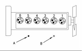
g00935559
Illustration 33
Cylinder and valve location
(A) Exhaust valves
(B) Inlet valves
3-5-6
2-4-6
4. Adjust the valve lash according to Table 13.
Use the following procedure to adjust the valve lash:
a. Lightly tap the rocker arm with a soft mallet.
This will ensure that the lifter roller seats
against the camshaft’s base circle.
1. Put the No. 1 piston at the top center position
on the compression stroke. Refer to Systems
Operation, Testing and Adjusting, “Finding Top
Center Position for No. 1 Piston”.
b. Loosen the adjustment locknut.
Table 12
c. Place the appropriate feeler gauge between
rocker arm and the valve bridge. Then, turn
the adjustment screw in a clockwise direction.
Slide the feeler gauge between the rocker arm
and the valve bridge. Continue turning the
adjustment screw until a slight drag is felt on
the feeler gauge. Remove the feeler gauge.
Compression
Stroke for No.
1 Piston
Inlet Valves
Exhaust Valves
0.38 ± 0.08 mm
(0.015 ± 0.003
inch)
0.76 ± 0.08 mm
(0.030 ± 0.003
inch)
Valve Lash
Cylinders
1-2-4
1-3-5
d. Tighten the adjustment locknut to a torque
of 30 ± 7 N·m (22 ± 5 lb ft). Do not allow
the adjustment screw to turn while you are
tightening the adjustment locknut. Recheck
the valve lash after tightening the adjustment
locknut.
2. Adjust the valve lash according to Table 12.
a. Lightly tap the rocker arm with a soft mallet.
This will ensure that the lifter roller seats
against the camshaft’s base circle.
5. Remove the timing bolt from the flywheel after all
adjustments to the valve lash have been made.
Reinstall the timing cover.
b. Loosen the adjustment locknut.
c. Place the appropriate feeler gauge between
rocker arm and the valve bridge. Then, turn
the adjustment screw in a clockwise direction.
Slide the feeler gauge between the rocker arm
and the valve bridge. Continue turning the
adjustment screw until a slight drag is felt on
the feeler gauge. Remove the feeler gauge.
Refer to Systems Operation, Testing and Adjusting,
“Electronic Unit Injector - Adjust”.
d. Tighten the adjustment locknut to a torque
of 30 ± 7 N·m (22 ± 5 lb ft). Do not allow
the adjustment screw to turn while you are
tightening the adjustment locknut. Recheck
the valve lash after tightening the adjustment
locknut.
This document has been printed from SPI². Not for Resale
![]()
![]()

KENR6231
37
Testing and Adjusting Section
Lubrication System
i02571670
Engine Oil Pressure - Test
The engine oil pressure may be checked
electronically by using the electronic service tool.
The engine oil pressure can be measured with the
electronic service tool. Refer to Troubleshooting for
information on the use of the electronic service tool.
Measuring Engine Oil Pressure
Work carefully around an engine that is running.
Engine parts that are hot, or parts that are moving,
can cause personal injury.
NOTICE
Keep all parts clean from contaminants.
Contaminants may cause rapid wear and shortened
component life.
g00977330
Illustration 34
Oil gallery plug
(1) Plug
NOTICE
1. Install Tool (A) into the oil gallery plugs (1).
Care must be taken to ensure that fluids are contained
during performance of inspection, maintenance, test-
ing, adjusting and repair of the product. Be prepared to
collect the fluid with suitable containers before open-
ing any compartment or disassembling any compo-
nent containing fluids.
Note: Engine oil pressure to the camshaft and main
bearings should be checked on each side of the
cylinder block at oil gallery plugs (1).
2. Start the engine. Refer to Operation and
Maintenance Manual, “Refill Capacities and
Recommendations” for the recommendations of
engine oil.
Dispose of all fluids according to local regulations and
mandates.
Table 14
3. Record the value of the engine oil pressure when
the engine is at operating temperature 100 °C
(212 °F).
Required Tools
Part
Tool
Number
Part Name
Quantity
The minimum engine oil pressure should be
approximately 275 to 414 kPa (40 to 59 psi).
A
-
Pressure Gauge
1
4. Compare the recorded engine oil pressure with
the oil pressure indicators on the instrument panel
and the engine oil pressure that is displayed on
the electronic service tool.
Tool (A) measures the oil pressure in the system.
5. An engine oil pressure indicator that has a defect
or an engine oil pressure sensor that has a defect
can give a false indication of a low oil pressure or
a high oil pressure. If there is a notable difference
between the engine oil pressure readings make
necessary repairs.
This document has been printed from SPI². Not for Resale
![]()
![]()
![]()
![]()
![]()
![]()
![]()

![]()
38
KENR6231
Testing and Adjusting Section
6. If low engine oil pressure is determined, refer to
2. Engine oil that is contaminated with fuel or coolant
will cause low engine oil pressure. High engine
oil level in the crankcase can be an indication
of contamination. Determine the reason for
contamination of the engine oil and make the
necessary repairs. Replace the engine oil with the
approved grade of engine oil. Refer to Operation
and Maintenance Manual, “Engine Oil” for the
recommendations of engine oil.
“Reasons for Low Engine Oil Pressure”.
7. If high engine oil pressure is determined, refer to
“Reason for High Engine Oil Pressure”.
Reasons for Low Engine Oil
Pressure
NOTICE
NOTICE
Keep all parts clean from contaminants.
Perkins oil filters are manufactured to Perkins speci-
fications. Use of an oil filter that is not recommended
by Perkins could result in severe damage to the en-
gine bearings, crankshaft, etc., as a result of the larger
waste particles from unfiltered oil entering the engine
lubricating system. Only use oil filters recommended
by Perkins.
Contaminants may cause rapid wear and shortened
component life.
NOTICE
Care must be taken to ensure that fluids are contained
during performance of inspection, maintenance, test-
ing, adjusting and repair of the product. Be prepared to
collect the fluid with suitable containers before open-
ing any compartment or disassembling any compo-
nent containing fluids.
3. If the engine oil bypass valves are held in the
open position, a reduction in the oil pressure can
be the result. This may be due to debris in the
engine oil. If the engine oil bypass valves are
stuck in the open position, remove each engine
oil bypass valve and clean each bypass valve
in order to correct this problem. You must also
clean each bypass valve bore. Install new engine
oil filters. New engine oil filters will prevent more
debris from causing this problem. For information
on the repair of the engine oil bypass valves, refer
to Disassembly and Assembly, “Engine Oil Filter
Base - Disassemble”.
Dispose of all fluids according to local regulations and
mandates.
• Engine oil level is low. Refer to Step 1.
• Engine oil is contaminated. Refer to Step 2.
• The engine oil bypass valves are open. Refer to
Step 3.
4. An oil line or an oil passage that is open, broken,
or disconnected will cause low engine oil pressure.
An open lubrication system could be caused by
a piston cooling jet that is missing or damaged.
Determine the reason for an open lubrication
system of the engine and make the necessary
repairs.
• The engine lubrication system is open. Refer to
Step 4.
• The oil pickup tube has a leak or a restricted inlet
screen. Refer to Step 5.
• The engine oil pump is faulty. Refer to Step 6.
Note: The piston cooling jets direct engine oil toward
the bottom of the piston in order to cool the piston.
This also provides lubrication for the piston pin.
Breakage, a restriction or incorrect installation of the
piston cooling jets will cause seizure of the piston.
• Engine Bearings have excessive clearance. Refer
to Step 7.
1. Check the engine oil level in the crankcase. The
oil level can possibly be too far below the oil pump
supply tube. This will cause the oil pump not to
have the ability to supply enough lubrication to the
engine components. If the engine oil level is low
add engine oil in order to obtain the correct engine
oil level. Refer to Operation and Maintenance
Manual, “Engine Oil” for the recommendations of
engine oil.
5. The inlet screen of the oil pickup tube for the
engine oil pump can have a restriction. This
restriction will cause cavitation and a loss of
engine oil pressure. Check the inlet screen on
the oil pickup tube and remove any material that
may be restricting engine oil flow. Low engine oil
pressure may also be the result of the oil pickup
tube that is drawing in air. Check the joints of the
oil pickup tube for cracks or a damaged O-ring
seal. Remove the engine oil pan in order to gain
access to the oil pickup tube and the oil screen.
Refer to Disassembly and Assembly, “Engine Oil
Pan - Remove and Install” for more information.
This document has been printed from SPI². Not for Resale
![]()
![]()
![]()
![]()
![]()
![]()
![]()
KENR6231
39
Testing and Adjusting Section
6. Check the following problems that may occur to
the engine oil pump.
NOTICE
Perkins oil filters are manufactured to Perkins speci-
fications. Use of an oil filter that is not recomme, nded
by Perkins could result in severe damage to the en-
gine bearings, crankshaft, etc., as a result of the larger
waste particles from unfiltered oil entering the engine
lubricating system. Only use oil filters recommended
by Perkins.
a. Air leakage in the supply side of the oil pump
will also cause cavitation and loss of oil
pressure. Check the supply side of the oil pump
and make necessary repairs. For information
on the repair of the engine oil pump, refer to
Disassembly and Assembly, “Engine Oil Pump
- Remove”.
b. Oil pump gears that have too much wear will
cause a reduction in oil pressure. Repair the
engine oil pump. For information on the repair
of the engine oil pump, refer to Disassembly
and Assembly, “Engine Oil Pump - Remove”.
i02553373
Excessive Bearing Wear -
Inspect
7. Excessive clearance at engine bearings will
cause low engine oil pressure. Check the
engine components that have excessive bearing
clearance and make the necessary repairs.
When some components of the engine show bearing
wear in a short time, the cause can be a restriction in
an oil passage.
Reason for High Engine Oil
Pressure
An engine oil pressure indicator may show that there
is enough oil pressure, but a component is worn
due to a lack of lubrication. In such a case, look at
the passage for the oil supply to the component.
A restriction in an oil supply passage will not allow
enough lubrication to reach a component. This will
result in early wear.
NOTICE
Keep all parts clean from contaminants.
Contaminants may cause rapid wear and shortened
component life.
i02553374
Excessive Engine Oil
NOTICE
Care must be taken to ensure that fluids are contained
during performance of inspection, maintenance, test-
ing, adjusting and repair of the product. Be prepared to
collect the fluid with suitable containers before open-
ing any compartment or disassembling any compo-
nent containing fluids.
Consumption - Inspect
Engine Oil Leaks on the Outside of
the Engine
Dispose of all fluids according to local regulations and
mandates.
Check for leakage at the seals at each end of the
crankshaft. Look for leakage at the gasket for the
engine oil pan and all lubrication system connections.
Look for any engine oil that may be leaking from
the crankcase breather. This can be caused by
combustion gas leakage around the pistons. A dirty
crankcase breather will cause high pressure in the
crankcase. A dirty crankcase breather will cause the
gaskets and the seals to leak.
Engine oil pressure will be high if the engine oil
bypass valves become stuck in the closed position
and the engine oil flow is restricted. Foreign matter
in the engine oil system could be the cause for the
restriction of the oil flow and the movement of the
engine oil bypass valves. If the engine oil bypass
valves are stuck in the closed position, remove
each bypass valve and clean each bypass valve in
order to correct this problem. You must also clean
each bypass valve bore. Install new engine oil
filters. New engine oil filters will prevent more debris
from causing this problem. For information on the
repair of the engine oil filter bypass valve, refer to
Disassembly and Assembly, “Engine Oil Filter Base -
Disassemble”.
Engine Oil Leaks into the
Combustion Area of the Cylinders
Engine oil that is leaking into the combustion area of
the cylinders can be the cause of blue smoke. There
are several possible ways for engine oil to leak into
the combustion area of the cylinders:
• Leaks between worn valve guides and valve stems
This document has been printed from SPI². Not for Resale
![]()
![]()
![]()
![]()
![]()
![]()
![]()
40
KENR6231
Testing and Adjusting Section
• Worn components or damaged components
(pistons, piston rings, or dirty return holes for the
engine oil)
• Incorrect installation of the compression ring and/or
the intermediate ring
• Leaks past the seal rings in the turbocharger shaft
• Overfilling of the crankcase
• Wrong dipstick or guide tube
Excessive consumption of engine oil can also
result if engine oil with the wrong viscosity is used.
Engine oil with a thin viscosity can be caused by fuel
leakage into the crankcase or by increased engine
temperature.
i02553375
Increased Engine Oil
Temperature - Inspect
If the oil temperature is high, then check for a
restriction in the oil passages of the oil cooler. A
restriction in the oil cooler will not cause low oil
pressure in the engine.
Determine if the oil cooler bypass valve is held in the
open position. This condition will allow the oil to pass
through the valve instead of the oil cooler. The oil
temperature will increase.
Refer to Operation and Maintenance Manual, “Refill
Capacities” for the correct lubricating oil.
This document has been printed from SPI². Not for Resale
![]()
KENR6231
41
Testing and Adjusting Section
Cooling System
5. Check the sending unit. In some conditions, the
temperature sensor in the engine sends signals
to a sending unit. The sending unit converts these
signals to an electrical impulse which is used by a
mounted gauge. If the sending unit malfunctions,
the gauge can show an incorrect reading. Also if
the electric wire breaks or if the electric wire shorts
out, the gauge can show an incorrect reading.
i02553376
Cooling System - Check
(Overheating)
6. Check the radiator.
Above normal coolant temperatures can be caused
by many conditions. Use the following procedure
to determine the cause of above normal coolant
temperatures:
a. Check the radiator for a restriction to coolant
flow. Check the radiator for debris, dirt, or
deposits on the inside of the radiator core.
Debris, dirt, or deposits will restrict the flow of
coolant through the radiator.
b. Check for debris or damage between the fins
of the radiator core. Debris between the fins
of the radiator core restricts air flow through
the radiator core. Refer to Systems Operation,
Testing and Adjusting, “Cooling System -
Inspect”.
Personal injury can result from escaping fluid un-
der pressure.
If a pressure indication is shown on the indicator,
push the release valve in order to relieve pressure
before removing any hose from the radiator.
c. Ensure that the radiator size is adequate for
the application. An undersized radiator does
not have enough area for the effective release
of heat. This may cause the engine to run
at a temperature that is higher than normal.
The normal temperature is dependent on the
ambient temperature.
1. Check the coolant level in the cooling system.
Refer to Operation and Maintenance Manual,
“Cooling System Coolant Level - Check”. If the
coolant level is too low, air will get into the cooling
system. Air in the cooling system will cause a
reduction in coolant flow and bubbles in the
coolant. Air bubbles will keep coolant away from
the engine parts, which will prevent the transfer of
heat to the coolant. Low coolant level is caused by
leaks or incorrectly filling the radiator.
7. Check the filler cap. A pressure drop in the
radiator can cause the boiling point to be lower.
This can cause the cooling system to boil. Refer
to Systems Operation, Testing and Adjusting,
“Cooling System - Test”.
2. Check the mixture of antifreeze and water. Refer
to Operation and Maintenance Manual, “Fluid
Recommendations”. If the coolant mixture is
incorrect, drain the system. Put the correct mixture
of water, antifreeze and coolant conditioner in the
cooling system.
8. Check the fan and/or the fan shroud.
a. The fan must be large enough to send air
through most of the area of the radiator core.
Ensure that the size of the fan and the position
of the fan are adequate for the application.
3. Check for air in the cooling system. Air can enter
the cooling system in different ways. The most
common causes of air in the cooling system
are not filling the cooling system correctly and
combustion gas leakage into the cooling system.
Combustion gas can get into the system through
inside cracks, a damaged cylinder head, or a
damaged cylinder head gasket. Air in the cooling
system causes a reduction in coolant flow and
bubbles in the coolant. Air bubbles keep coolant
away from the engine parts, which prevents the
transfer of heat to the coolant.
b. The fan shroud must be the proper size and
the fan shroud must be positioned correctly.
Ensure that the size of the fan shroud and the
position of the fan shroud are adequate for the
application.
9. If the fan is belt driven, check for loose drive belts.
A loose fan drive belt will cause a reduction in the
air flow across the radiator. Check the fan drive
belt for proper belt tension. Adjust the tension of
the fan drive belt, if necessary. Refer to Systems
Operation, Testing and Adjusting, “Belt Tension
Chart”.
4. Check the water temperature gauge. A water
temperature gauge which does not work correctly
will not show the correct temperature. Refer
to Systems Operation, Testing and Adjusting,
“Cooling System - Inspect”.
This document has been printed from SPI². Not for Resale
![]()
![]()
![]()
42
KENR6231
Testing and Adjusting Section
10. Check the cooling system hoses and clamps.
Damaged hoses with leaks can normally be seen.
Hoses that have no visual leaks can soften during
operation. The soft areas of the hose can become
kinked or crushed during operation. These areas
of the hose can cause a restriction in the coolant
flow. Hoses become soft and/or get cracks
after a period of time. The inside of a hose can
deteriorate, and the loose particles of the hose
can cause a restriction of the coolant flow. Refer
to Operation and Maintenance Manual, “Hoses
and Clamps - Inspect/Replace”.
14. Check the water temperature regulator. A water
temperature regulator that does not open, or
a water temperature regulator that only opens
part of the way can cause overheating. Refer to
Systems Operation, Testing and Adjusting, “Water
Temperature Regulator - Test”.
15. Check the water pump. A water pump with a
damaged impeller does not pump enough coolant
for correct engine cooling. Remove the water
pump and check for damage to the impeller. Refer
to Systems Operation, Testing and Adjusting,
“Water Pump - Test”.
11. Check for a restriction in the air inlet system.
A restriction of the air that is coming into the
engine can cause high cylinder temperatures.
High cylinder temperatures cause higher than
normal temperatures in the cooling system. Refer
to Systems Operation, Testing and Adjusting, “Air
Inlet and Exhaust System - Inspect”.
16. Check the air flow through the engine
compartment. The air flow through the radiator
comes out of the engine compartment. Ensure
that the filters, air conditioner, and similar items
are not installed in a way that prevents the free
flow of air through the engine compartment.
a. If the measured restriction is higher than the
maximum permissible restriction, remove the
foreign material from the engine air cleaner
element or install a new engine air cleaner
element. Refer to Operation and Maintenance
Manual, “Engine Air Cleaner Element -
Clean/Replace”.
17. Check the aftercooler. A restriction of air flow
through the air to air aftercooler (if equipped) can
cause overheating. Check for debris or deposits
which would prevent the free flow of air through
the aftercooler.
18. Consider high outside temperatures. When
outside temperatures are too high for the rating
of the cooling system, there is not enough of a
temperature difference between the outside air
and coolant temperatures.
b. Check for a restriction in the air inlet system
again.
c. If the measured restriction is still higher than
the maximum permissible restriction, check the
air inlet piping for a restriction.
19. Consider high altitude operation. The cooling
capacity of the cooling system goes down as
the engine is operated at higher altitudes. A
pressurized cooling system that is large enough to
keep the coolant from boiling must be used.
12. Check for a restriction in the exhaust system.
A restriction of the air that is coming out of the
engine can cause high cylinder temperatures.
a. Make a visual inspection of the exhaust system.
Check for damage to exhaust piping or for a
damaged muffler. If no damage is found, check
the exhaust system for a restriction. Refer to
Systems Operation, Testing and Adjusting, “Air
Inlet and Exhaust System - Inspect”.
i02553378
Cooling System - Inspect
Cooling systems that are not regularly inspected are
the cause for increased engine temperatures. Make
a visual inspection of the cooling system before any
tests are performed.
b. If the measured restriction is higher than the
maximum permissible restriction, there is a
restriction in the exhaust system. Repair the
exhaust system, as required.
13. Check the shunt line, if the shunt system is
used. The shunt line must be submerged in the
expansion tank. A restriction of the shunt line
from the radiator top tank to the engine water
pump inlet will cause a reduction in water pump
efficiency. A reduction in water pump efficiency
will result in low coolant flow and overheating.
Personal injury can result from escaping fluid un-
der pressure.
If a pressure indication is shown on the indicator,
push the release valve in order to relieve pressure
before removing any hose from the radiator.
This document has been printed from SPI². Not for Resale
![]()
![]()
![]()
KENR6231
43
Testing and Adjusting Section
1. Check the coolant level in the cooling system.
Refer to Operation and Maintenance Manual,
“Cooling System Coolant Level - Check”.
2. Check the quality of the coolant. The coolant
should have the following properties:
• Color that is similar to new coolant
• Odor that is similar to new coolant
• Free from dirt and debris
If the coolant does not have these properties,
drain the system and flush the system. Refill
the cooling system with the correct mixture of
water, antifreeze, and coolant conditioner. Refer
to Operation and Maintenance Manual, “Fluid
Recommendations”.
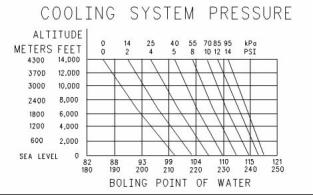
g00921815
Illustration 35
Boiling point of water
Remember that temperature and pressure work
together. When a diagnosis is made of a cooling
system problem, temperature and pressure must be
checked. Cooling system pressure will have an effect
on the cooling system temperature. For an example,
refer to Illustration 35. This will show the effect of
pressure on the boiling point (steam) of water. This
will also show the effect of height above sea level.
3. Look for leaks in the system.
Note: A small amount of coolant leakage across
the surface of the water pump seals is normal. This
leakage is required in order to provide lubrication for
this type of seal. A hole is provided in the water pump
housing in order to allow this coolant/seal lubricant
to drain from the pump housing. Intermittent leakage
of small amounts of coolant from this hole is not an
indication of water pump seal failure.
Personal injury can result from hot coolant, steam
and alkali.
4. Ensure that the air flow through the radiator does
not have a restriction. Look for bent core fins
between the folded cores of the radiator. Also, look
for debris between the folded cores of the radiator.
At operating temperature, engine coolant is hot
and under pressure. The radiator and all lines
to heaters or the engine contain hot coolant or
steam. Any contact can cause severe burns.
5. Inspect the drive belts for the fan.
6. Check for damage to the fan blades.
Remove filler cap slowly to relieve pressure only
when engine is stopped and radiator cap is cool
enough to touch with your bare hand.
7. Look for air or combustion gas in the cooling
system.
Cooling System Conditioner contains alkali. Avoid
contact with skin and eyes.
8. Inspect the filler cap, and check the surface that
seals the filler cap. This surface must be clean.
The coolant level must be to the correct level in order
to check the coolant system. The engine must be
cold and the engine must not be running.
i02553379
Cooling System - Test
After the engine is cool, loosen the pressure cap
in order to relieve the pressure out of the cooling
system. Then remove the pressure cap.
This engine has a pressure type cooling system. A
pressure type cooling system has two advantages.
The cooling system can be operated in a safe manner
at a temperature higher than the normal boiling point
(steam) of water.
The level of the coolant should not be more than
13 mm (0.5 inch) from the bottom of the filler pipe. If
the cooling system is equipped with a sight glass,
the coolant should be to the proper level in the sight
glass.
This type of system prevents cavitation in the water
pump. Cavitation is the forming of low pressure
bubbles in liquids that are caused by mechanical
forces. It is difficult to create a pocket of air in this
type of cooling system.
This document has been printed from SPI². Not for Resale
![]()
![]()
![]()
![]()
44
KENR6231
Testing and Adjusting Section
Checking the Filler Cap
• Seal
Table 15
• Surface for seal
Required Tools
Remove any deposits that are found on these
items, and remove any material that is found on
these items.
Tool
Part Number
Part Description
Qty
A
GE50031
Pressurizing Pump
1
2. Install the filler cap onto Tooling (A).
One cause for a pressure loss in the cooling system
can be a damaged seal on the radiator filler cap.
3. Look at the gauge for the exact pressure that
opens the filler cap.
4. Compare the gauge reading with the opening
pressure that is listed on the filler cap.
5. If the filler cap is damaged, replace the filler cap.
Testing The Radiator And Cooling
System For Leaks
Table 16
Required Tools
Tool
Part Number
Part Description
Qty
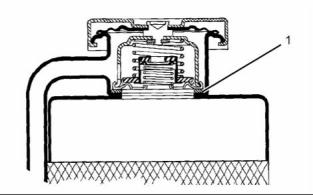
g01096114
Illustration 36
Typical schematic of filler cap
A
GE50031
Pressurizing Pump
1
(1) Sealing surface of both filler cap and radiator
Use the following procedure in order to check the
cooling system for leaks:
Personal injury can result from hot coolant, steam
and alkali.
Personal injury can result from hot coolant, steam
and alkali.
At operating temperature, engine coolant is hot
and under pressure. The radiator and all lines
to heaters or the engine contain hot coolant or
steam. Any contact can cause severe burns.
At operating temperature, engine coolant is hot
and under pressure. The radiator and all lines
to heaters or the engine contain hot coolant or
steam. Any contact can cause severe burns.
Remove filler cap slowly to relieve pressure only
when engine is stopped and radiator cap is cool
enough to touch with your bare hand.
Remove filler cap slowly to relieve pressure only
when engine is stopped and radiator cap is cool
enough to touch with your bare hand.
Cooling System Conditioner contains alkali. Avoid
contact with skin and eyes.
Cooling System Conditioner contains alkali. Avoid
contact with skin and eyes.
To check for the amount of pressure that opens the
filler cap, use the following procedure:
1. After the engine is cool, loosen the filler cap slowly
and allow pressure out of the cooling system.
Then remove the filler cap from the radiator.
1. After the engine cools, carefully loosen the filler
cap. Slowly release the pressure from the cooling
system. Then, remove the filler cap.
2. Ensure that the coolant level is above the top of
the radiator core.
Carefully inspect the filler cap. Look for any
damage to the seals and to the sealing surface.
Inspect the following components for any foreign
substances:
3. Install Tooling (A) onto the radiator.
4. Take the pressure reading on the gauge to 20 kPa
(3 psi) more than the pressure on the filler cap.
• Filler cap
This document has been printed from SPI². Not for Resale
![]()

![]()
![]()
![]()

![]()
![]()
KENR6231
45
Testing and Adjusting Section
5. Check the radiator for leakage on the outside.
Coolant temperature can also be read on the display
screens of the Electronic Service Tool.
6. Check all connection points for leakage, and
check the hoses for leakage.
The cooling system does not have leakage only if the
following conditions exist:.
• You do not observe any outside leakage.
• The reading remains steady after five minutes.
The inside of the cooling system has leakage only if
the following conditions exist:
• The reading on the gauge goes down.
• You do NOT observe any outside leakage.
Make any repairs, as required.
Test For The Water Temperature
Gauge
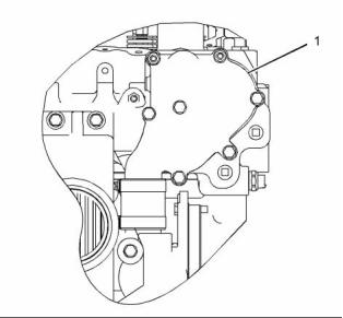
g01096115
Illustration 37
Typical example
(1) Water manifold assembly
Table 17
Required Tools
Tool
Part Number
Part Description
Qty
Remove a plug from water manifold assembly (1).
Install Tooling (A) in the open port:
A
-
Thermometer
1
A temperature indicator of known accuracy can also
be used to make this check.
Start the engine. Run the engine until the temperature
reaches the desired range according to the test
thermometer. If necessary, place a cover over part of
the radiator in order to cause a restriction of the air
flow. The reading on the water temperature indicator
should agree with the test thermometer within the
tolerance range of the water temperature indicator.
Personal injury can result from escaping fluid un-
der pressure.
If a pressure indication is shown on the indicator,
push the release valve in order to relieve pressure
before removing any hose from the radiator.
i02553380
Water Temperature Regulator
- Test
Making contact with a running engine can cause
burns from hot parts and can cause injury from
rotating parts.
When working on an engine that is running, avoid
contact with hot parts and rotating parts.
Check the accuracy of the water temperature
indicator or water temperature sensor if you find
either of the following conditions:
Personal injury can result from escaping fluid un-
der pressure.
If a pressure indication is shown on the indicator,
push the release valve in order to relieve pressure
before removing any hose from the radiator.
• The engine runs at a temperature that is too hot,
but a normal temperature is indicated. A loss of
coolant is found.
• The engine runs at a normal temperature, but a
hot temperature is indicated. No loss of coolant
is found.
1. Remove the water temperature regulator from the
engine.
This document has been printed from SPI². Not for Resale
![]()

![]()
![]()
![]()
![]()
![]()
![]()
![]()
46
KENR6231
Testing and Adjusting Section
2. Heat water in a suitable container until the
temperature is 98 °C (208 °F).
Making contact with a running engine can cause
burns from hot parts and can cause injury from
rotating parts.
3. Hang the water temperature regulator in the
container of water. The water temperature
regulator must be below the surface of the water
and away from the sides and the bottom of the
container.
When working on an engine that is running, avoid
contact with hot parts and rotating parts.
4. Keep the water at the correct temperature for ten
minutes.
Perform the following procedure in order to determine
if the water pump is operating correctly:
5. After ten minutes, remove the water temperature
regulator. Ensure that the water temperature
regulator is open.
1. Remove the plug from port (2).
2. Install Tooling (A) in port (2).
Replace the water temperature regulator if the
water temperature regulator is not open at the
specified temperature. Refer to Specifications,
“Water Temperature Regulator”.
3. Start the engine. Run the engine until the coolant
is at operating temperature.
4. Note the water pump pressure. The water pump
pressure should be 100 to 125 kPa (15 to 18 psi).
i02553381
Water Pump - Test
Table 18
Required Tools
Tool
Part Number
Part Description
Qty
A
GE50033
Pressure Gauge
1
g01033819
Illustration 38
Typical example
(1) Water outlet
(2) Port
(3) Temperature regulator housing
(4) Water pump
(5) Port
This document has been printed from SPI². Not for Resale
![]()

![]()

![]()
![]()
KENR6231
47
Testing and Adjusting Section
Basic Engine
Connecting rod bearings are available with smaller
inside diameters than the original size bearings.
These bearings are for crankshafts that have been
ground.
i02553382
Piston Ring Groove - Inspect
If necessary, replace the connecting rod bearings.
Refer to Disassembly and Assembly, “Connecting
Rod Bearings - Remove” and Disassembly and
Assembly, “Connecting Rod Bearings - Install” for the
correct procedure.
Inspect the Piston and the Piston
Rings
i02553396
1. Check the piston for wear and other damage.
Main Bearings - Inspect
2. Check that the piston rings are free to move in the
grooves and that the rings are not broken.
Main bearings are available with smaller inside
diameters than the original size bearings. These
bearings are for crankshafts that have been ground.
Inspect the Clearance of the Piston
Ring
If necessary, replace the main bearings. Refer
to Disassembly and Assembly, “Crankshaft Main
Bearings - Remove and Install” for the correct
procedure.
1. Remove the piston rings and clean the grooves
and the piston rings.
2. Fit new piston rings in the piston grooves.
3. Check the clearance for the piston ring by placing
a suitable feeler gauge between the piston groove
and the top of piston ring. Refer to Specifications,
“Piston and Rings” for the dimensions.
i02571419
Cylinder Block - Inspect
Inspect the Piston Ring End Gap
1. Clean all of the coolant passages and the oil
passages.
1. Clean all carbon from the top of the cylinder bores.
2. Check the cylinder block for cracks and damage.
2. Place each piston ring in the cylinder bore just
below the cylinder ring ridge.
3. The top deck of the cylinder block must not be
machined. This will affect the depth of the cylinder
liner flange and the piston height above the
cylinder block.
3. Use a suitable feeler gauge to measure piston
ring end gap. Refer to Specifications, “Piston and
Rings” for the dimensions.
4. Check the front camshaft bearing for wear. Refer
to Specifications, “Camshaft Bearings” for the
correct specification of the camshaft bearing. If a
new bearing is needed, use a suitable adapter to
press the bearing out of the bore. Ensure that the
oil hole in the new bearing faces the front of the
block. The oil hole in the bearing must be aligned
with the oil hole in the cylinder block. The bearing
must be aligned with the face of the recess.
Note: The coil spring must be removed from the oil
control ring before the gap of the oil control ring is
measured.
i02553391
Connecting Rod Bearings -
Inspect
The connecting rod bearings fit tightly in the bore in
the rod. If the bearing joints are worn, check the bore
size. This can be an indication of wear because of
a loose fit.
This document has been printed from SPI². Not for Resale
![]()
48
KENR6231
Testing and Adjusting Section
i02553404
Cylinder Liner Projection -
Inspect
Table 19
Required Tools
Tool
A
Part Number
GE50005
Part Description
Clamp bolt
Qty
6
B
GE50006
Clamp washer
Fibre washer
6
C
GE50007
6
Cylinder liner
projection tool
D
GE50002
1
Note: The projection of the cylinder liner is measured
from the top of the cylinder liner to the top of the
spacer plate.
g01096458
Illustration 39
Liner Projection Components
(1) Bolt
(2) Washer
(3) Washer
(4) Spacer plate
(5) Cylinder liner
(6) Block
This document has been printed from SPI². Not for Resale
![]()
![]()
KENR6231
49
Testing and Adjusting Section
g00443044
Illustration 40
This document has been printed from SPI². Not for Resale
![]()

50
KENR6231
Testing and Adjusting Section
1. Ensure that the top face of the cylinder block (6)
is clean. Install a new spacer plate gasket and a
clean spacer plate.
Do not exceed the maximum liner projection of
0.152 mm (0.006 inch). The excessive liner projection
will contribute to cracking of the liner flange.
2. Install the cylinder liners to the cylinder block
without seals or bands. Ensure that the cylinder
liners are installed to the original positions.
When the liner projection is correct, put a temporary
mark on the liner and the spacer plate. Set the liners
aside.
3. Install Tooling (B) and Tooling (C) to Tooling (A).
Note: Refer to Disassembly and Assembly, “Cylinder
Liner - Install” for the correct final installation
procedure for the cylinder liners.
Refer to illustration 39.
4. Install Tooling (A) around the liner. Refer to
illustration 39.
i02553516
Flywheel - Inspect
5. Tighten the bolts (6) to a torque of 95 N·m (70 lb ft).
6. Use Tooling (D) to measure the cylinder liner
projection at "A", "B", "C" and "D". Refer to
illustration 40.
Face Runout (Axial Eccentricity) of
the Flywheel
7. Record the measurements for the cylinder.
8. Repeat steps 3 to 7 for each cylinder.
Table 21
Required Tools
9. Add the four readings for each cylinder. Divide the
sum by four in order to find the average.
Tool
Part Number
Part Description
Qty
A
21825617
Dial Indicator Group
1
Table 20
Specifications
0.025 to 0.152 mm
Liner Projection
(0.0010 to 0.0060 inch)
Maximum Variation In
0.051 mm (0.0020 inch)
Each Liner
Maximum Average
Variation Between
Adjacent Liners
0.051 mm (0.0020 inch)
0.102 mm (0.0040 inch)
Maximum Variation
Between All Liners
Note: If the liner projection changes around the liner,
turn the liner to a new position within the bore. If the
liner projection is not within specifications, move the
liner to a different bore. Inspect the top face of the
cylinder block.
If the cylinder liner projections are below 0.025 mm
(0.0010 inch) or 0.051 mm (0.0020 inch) corrective
action must be taken. A thinner spacer plate may
be used. The thinner spacer plate is available from
your Perkins distributor. The plates are 0.076 mm
(0.0030 inch) thinner than the original plate. The
plates will increase the liner projection. Use these
spacer plates to compensate for low liner projections
which are less than the 0.076 mm (0.0030 inch). Use
these spacer plates if inspection of the top face of
the cylinder block reveals no measurable damage
directly under the liner flanges but the average liner
projection is less than 0.076 mm (0.0030 inch).
g00286049
Illustration 41
Checking face runout of the flywheel
1. Install Tooling (A). Refer to illustration 41. Always
put a force on the crankshaft in the same direction
before the dial indicator is read. This will remove
any crankshaft end clearance.
2. Set the dial indicator to read 0.0 mm (0.00 inch).
This document has been printed from SPI². Not for Resale
![]()


![]()
KENR6231
51
Testing and Adjusting Section
3. Turn the flywheel at intervals of 45 degrees and
read the dial indicator.
4. Take the measurements at all four points. The
difference between the lower measurements and
the higher measurements that are performed at
all four points must not be more than 0.15 mm
(0.006 inch), which is the maximum permissible
face runout (axial eccentricity) of the flywheel.
Bore Runout (Radial Eccentricity)
of the Flywheel
Table 22
g00286058
Illustration 43
Flywheel clutch pilot bearing bore
Required Tools
Tool
Part Number
Part Description
Qty
5. To find the runout (eccentricity) of the pilot bearing
A
21825617
Dial Indicator Group
1
bore, use the preceding procedure.
6. The runout (eccentricity) of the bore for the pilot
bearing in the flywheel must not exceed 0.13 mm
(0.005 inch).
i02553531
Flywheel Housing - Inspect
Table 23
Required Tools
Tool
Part Number
Part Description
Qty
A
21825617
Dial Indicator Group
1
Face Runout (Axial Eccentricity) of
the Flywheel Housing
g01278054
Illustration 42
Checking bore runout of the flywheel
1. Install Tooling (A). Refer to illustration 42.
2. Set the dial indicator to read 0.0 mm (0.00 inch).
3. Turn the flywheel at intervals of 45 degrees and
read the dial indicator.
4. Take the measurements at all four points. The
difference between the lower measurements and
the higher measurements that are performed at
all four points must not be more than 0.15 mm
(0.006 inch) for the maximum permissible face
runout (radial eccentricity) of the flywheel.
g00285931
Illustration 44
Typical example
If you use any other method except the method that
is given here, always remember that the bearing
clearance must be removed in order to receive the
correct measurements.
This document has been printed from SPI². Not for Resale
![]()

![]()
![]()

![]()